1997 MERCEDES-BENZ ML350 child restraint
[x] Cancel search: child restraintPage 534 of 4133
67
Restraint systems
Te ch n ica l
data
Instruments
and controls Operation
Driving Instrument
cluster display Practical hints Car care Index
Installation of infant and child restraint systems
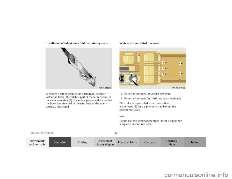
To secure a tether strap to the anchorage, securely
fasten the hook (1), which is part of the tether strap, to
the anchorage ring (2). For safety, please make sure that
the hook has attached to the ring beyond the safety
catch, as illustrated. Vehicle without third row seats
3 Tether anchorages for second row seats
4 Tether anchorages for third row seats (optional)
This vehicle is provided with three tether
anchorages (3) for a top tether strap behind the
second row seats.
Note:
Do not use the tether anchorages (4) for a top tether
strap on a second row seat.
Page 535 of 4133
68
Restraint systems
Te ch n ica l
data
Instruments
and controls Operation
Driving Instrument
cluster display Practical hints Car care Index
Vehicle with third row seats
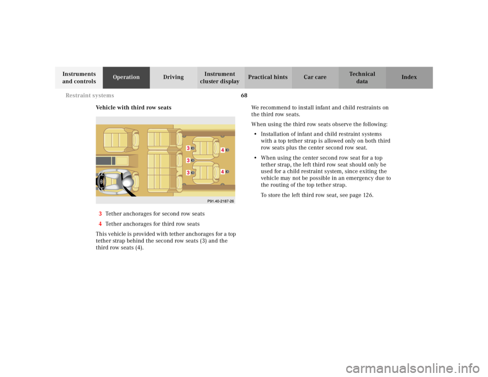
3 Tether anchorages for second row seats
4 Tether anchorages for third row seats
This vehicle is provided with tether anchorages for a top
tether strap behind the second row seats (3) and the
third row seats (4). We recommend to install infant and child restraints on
the third row seats.
When using the third row seats observe the following:
• Installation of infant and child restraint systems
with a top tether strap is allowed only on both third
row seats plus the center second row seat.
• When using the center second row seat for a top
tether strap, the left third row seat should only be
used for a child restraint system, since exiting the
vehicle may not be possible in an emergency due to
the routing of the top tether strap.
To store the left third row seat, see page 126.
Page 536 of 4133
69
Restraint systems
Te ch n ica l
data
Instruments
and controls Operation
Driving Instrument
cluster display Practical hints Car care Index
Important!
An infant and child restraint system must not be
installed on the right second row seat while a passenger
rides in a third row seat. Use of the easy-entry / exit
feature is not possible. See page 123 for easy-entry / exit
feature. Note:
When installing an infant or child restraint system with
a top tether strap on the left second row seat, the left
third row seat should not be occupied. For storage of the
left third row seat, see page 126.
Page 686 of 4133
219
Malfunction and indicator lamps
Te ch n ica l
data
Instruments
and controls Operation Driving
Instrument
cluster display Practical hints Car care Index
Brake warning lamp
When the brake warning lamp appears
while the engine is running, this means:
• there is insufficient brake fluid in the reservoir
(engine running and parking brake released), or
• the parking brake is set (engine running)
• the electronic brake proportioning (EBP) system is
malfunctioning.
Note:
If you find that the minimum mark on the brake fluid
reservoir is reached, have the brake system checked for
brake pad thickness and leaks. Supplemental restraint system (SRS) indicator lamp
The operational readiness of the airbag
system is verified by the indicator lamp
“SRS” in the instrument cluster when
turning the key in steering lock to position 1 or 2. If no
fault is detected, the lamp will go out after
approximately 5 seconds; after the lamp goes out, the
system continues to monitor the components and
circuitry of the airbag system and will indicate a
malfunction by coming on again.
See page 56 for notes on airbags, page 55 for belt
tensioners, and page 65 for infant and child seat
restraints.
Wa r n i n g !
Driving with the brake warning lamp illuminated
can result in an accident. Have your brake system
checked immediately if the brake warning lamp
stays on. Don’t add brake fluid before checking the
brake system. Overfilling the brake fluid reservoir
can result in spilling brake fluid on hot engine
parts and the brake fluid catching fire. You can be
seriously burned.BRAKE
Wa r n i n g !
In the event a malfunction of the “SRS” is indicated
as outlined above, the “SRS” may not be
operational. For your safety, we strongly
recommend that you visit an authorized
Mercedes-Benz Light Truck Center immediately to
have the system checked; otherwise the “SRS” may
not be activated when needed in an accident, which
could result in serious or fatal injury, or it might
deploy unexpectedly and unnecessarily which
could also result in injury.SRS
Page 768 of 4133

301
Index
Te ch n ica l
data
Instruments
and controls Operation Driving
Instrument
cluster display Practical hints Car care
Index
Brake fluid ............................................................. 175, 294
Brake warning lamp ................................................. 219
Capacity ......................................................................293
Brake pad wear indicator .............................................225
Brake warning lamp ...................................................... 219 Brake fluid low .......................................................... 219
Brakes ....................................................173, 175, 293, 294
CCapacities Fuels, coolants, lubricants etc. ...............................292
Cargo area ....................................................................... 131 Hooks .......................................................................... 133
Loading instructions ................................................ 136
Cargo area cover blind .................................................. 137
Cargo compartment lamp .............................................. 111
Cargo floor plates
Removable .................................................................. 129
Storage ........................................................................ 130
Cargo tie-down rings ..................................................... 132
Catalytic converter ........................................................ 160
Cellular telephone ......................................................... 139
Center console .................................................................. 20
Central locking switch .................................................... 32 Central locking system .................................................... 26
Automatic central locking .........................................32
Locking and unlocking ............................................... 27
Mechanical keys ..........................................................29
Panic button .................................................................28
Remote control ............................................................26
Unlocking the liftgate ................................................. 28
Vehicle keys .................................................................24
Changing wheels ........................................................... 245 Inflating the space-saver tire ................................. 249
Charge indicator lamp .................................................. 223
CHECK ENGINE malfunction indicator lamp ............ 218
Check regularly and before a long trip ....................... 215
Checking engine oil level Via engine oil level indicator ....................................89
Via oil dipstick .......................................................... 233
Child restraint ..............................................38, 46, 53, 65
Cleaning and care of the vehicle ................................ 278
Climate control .................................................................98 Air recirculation ........................................................102
Basic setting ...............................................................100
Defogging windows ................................................... 101
Defrosting windshield .............................................. 101
Dust filter ...................................................................102
Rear window defroster ............................................. 103
Special settings ......................................................... 101
Page 772 of 4133

305
Index
Te ch n ica l
data
Instruments
and controls Operation Driving
Instrument
cluster display Practical hints Car care
Index
Headlamp cleaning system ............................................ 94
Headlights ......................................................................... 90
Heated seats ..................................................................... 44
Hood ................................................................................. 231
Hooks ............................................................................... 133
IIdentification labels .......................................................285
Illuminated vanity mirrors ............................................113
Indicator lamps in the instrument cluster ................... 78
Infant and child restraint system Installation ................................................................... 67
Infant and child restraint systems ................................ 65
Inflating the space-saver tire .......................................249
Information call See Tele Aid ............................................................... 148
Instrument cluster ........................................................... 76
Activating display ....................................................... 80
Display illumination ................................................... 80
Indicator lamps ........................................................... 78
Malfunction and indicator lamps ........................... 218
Instrument lamps ............................................................ 80 Instruments and controls ............................................... 18
Interior General notes ............................................................. 114
Interior lighting .............................................................. 110
JJump starting ................................................................. 253KKeys, vehicle .....................................................................24LLamps, exterior .............................................................. 260 Adjusting headlamp aim ......................................... 268
Auxiliary fog lamp ............................................. 92, 264
Fog lamps .....................................................................93
Headlamp assembly ......................................... 261, 262
Headlamps .................................90, 261, 262, 268, 280
High mounted stop lamp ......................................... 267
License plate lamps ................................................. 267
Low and high beam ............................................90, 263
Page 783 of 4133
SERVICING
SRS AIR BAG label on driver-side door latch post indicates SRS replacement date for air bag units. All SRS
components must be thoroughly inspected, including wiring harness. Before component replacement, check for
SRS fault codes by performing system operation check. See SYSTEM OPERATION CHECK
. SRS service
life is 10 years from manufactured date or 10 years from SRS replacement date after accident related repairs are
completed.
SYSTEM OPERATION CHECK
SRS warning light indicates SRS and Emergency Tensioning Retractor (ETR) system readiness. Turn ignition
on. SRS warning light will illuminate, then turn off after approximately 4-6 seconds indicating SRS system is
functioning properly. If SRS warning light does not illuminate, illuminates while driving or is continuously
illuminated, there is a system fault. Repair malfunctioning system.
AIR BAG SAFETY PRECAUTIONS
Observe these precautions when servicing the air bag system:
When working around SRS components and before any repairs are performed, disable air bag system. See
DISABLING & ACTIVATING AIR BAG SYSTEM
.
Before straightening any damage to body, or before performing electrical arc-welding, disable air bag
system. See DISABLING & ACTIVATING AIR BAG SYSTEM
.
Always wear safety glasses and gloves when handling a deployed air bag module. Air bag module may
contain sodium hydroxide deposits which are irritating to the skin.
Always use control module and impact sensors made by same manufacturer. Using components produced
by different manufacturers could cause accidental air bag or ETR deployment.
DO NOT repair any portion of SRS wiring harness.
If any SRS component is dropped from a height greater than 1.6 feet (0.5 m), it must be replaced.
If SRS components show signs of damage, they must be replaced.
Always handle air bag module with trim cover facing away from your body.
Always place air bag module on workbench with trim cover up, away from loose objects.
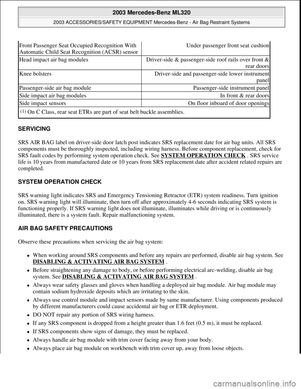
Front Passenger Seat Occupied Recognition With
Automatic Child Seat Recognition (ACSR) sensorUnder passenger front seat cushion
Head impact air bag modulesDriver-side & passenger-side roof rails over front &
rear doors
Knee bolstersDriver-side and passenger-side lower instrument
panel
Passenger-side air bag modulePassenger-side instrument panel
Side impact air bag modulesIn front & rear doors
Side impact sensorsOn floor inboard of door openings
(1)On C Class, rear seat ETRs are part of seat belt buckle assemblies.
2003 Mercedes-Benz ML320
2003 ACCESSORIES/SAFETY EQUIPMENT Mercedes-Benz - Air Bag Restraint Systems
me
Saturday, October 02, 2010 3:32:07 PMPage 2 © 2006 Mitchell Repair Information Company, LLC.
Page 808 of 4133

ContentsSafety and Security........................... 57
Occupant safety................................... 58
Airbags ........................................... 59
Seat belts ....................................... 64
Children in the vehicle .................... 67
Blocking of rear door
window operation ........................... 73
Panic alarm .......................................... 75
Activating ....................................... 75
Deactivating ................................... 75
Driving and safety systems .................. 76
ABS ................................................ 76
BAS ................................................ 78
4-ETS .............................................. 79
EBP................................................. 80
ESP ................................................. 80
Anti-theft systems................................ 83
Immobilizer..................................... 83
Anti-theft alarm .............................. 83
Tow-away alarm,
glass breakage sensor.................... 84
Controls in detail............................... 87
Locking and unlocking ......................... 88
Remote control with folding key..... 88
Opening the doors
from the inside ............................... 90
Opening the liftgate ....................... 91
Closing the liftgate ......................... 92
Automatic central locking .............. 93
Locking and unlocking
from the inside ............................... 94
Seats ................................................... 95
Removing and installing
front seat head restraints............... 95
Rear seat head restraints ............... 96
Heated seats* ................................ 98
Rear seats ...................................... 99
Third row seats* .......................... 102
Memory function* ............................. 105
Storing exterior rear view mirror
parking position ........................... 105
Storing positions in memory ........ 106
Recalling positions from memory . 106Lighting ............................................. 107
Combination switch ..................... 107
Fog lamps .................................... 111
Hazard warning flasher ................ 112
Interior lighting ............................ 112
Instrument cluster ............................. 116
Instrument cluster illumination .... 116
Coolant temperature gauge ......... 117
Display in the speedometer ......... 117
Resetting trip odometer ............... 118
Tachometer .................................. 118
Outside temperature indicator ..... 118
Setting the clock .......................... 118
Automatic transmission ..................... 119
One-touch gearshifting ................ 120
Gear ranges ................................. 121
Gear selector lever position ......... 122
Accelerator position ..................... 123
Towing a trailer ............................ 124
Emergency operation
(Limp Home Mode) ...................... 124