1997 MERCEDES-BENZ ML350 sensor
[x] Cancel search: sensorPage 210 of 4133
160 Catalytic converter
Te ch n ica l
data Instruments
and controlsOperationDrivingInstrument
cluster displayPractical hints Car care Index
Catalytic converter
Your Mercedes-Benz is equipped with monolithic type
catalytic converters, an important element in
conjunction with the oxygen sensors to achieve
substantial control of the pollutants in the exhaust
emissions. Keep your vehicle in proper operating
condition by following our recommended maintenance
instructions as outlined in your Service Booklet.Caution!
To prevent damage to the catalytic converters, use only
premium unleaded gasoline in this vehicle.
Any noticeable irregularities in engine operation should
be repaired promptly. Otherwise, excessive unburned
fuel may reach the catalytic converter causing it to
overheat, which could start a fire.
Wa r n i n g !
As with any vehicle, do not idle, park or operate
this vehicle in areas where combustible materials
such as grass, hay or leaves can come into contact
with the hot exhaust system, as these materials
could be ignited and cause a vehicle fire.
Page 354 of 4133
304 Index
Te ch n ica l
data Instruments
and controlsOperation DrivingInstrument
cluster displayPractical hints Car careIndex
FFirst aid kit .....................................................................228
Flexible service system (FSS) ........................................ 87
FSS indicator lamp ............................................ 79, 225
Floor plates
Removable .................................................................. 129
Fog lamp switch ........................................................ 92, 93
Four ETS
LOW RANGE – 4-ETS+ .............................................204
Malfunction indicator lamp ..................................... 221
Four wheel electronic traction system (4-ETS+) .......203
Malfunction indicator lamp ..................................... 221
Fuel
Gasoline additives ....................................................296
Premium unleaded gasoline ................. 213, 293, 295
Fuel filler flap
Manual release .......................................................... 274
Fuel requirements .........................................................295
Fuel reserve warning ....................................................220
Fuels, coolants, lubricants etc. - Capacities ..............292
Fuses, electrical .............................................................228
GGarage door opener .......................................................140
Gasoline
Additives .................................................................... 296
Fuel requirements ................................................... 295
Premium unleaded .................................................. 295
General notes on the central locking system .............. 26
Glass breakage sensor .................................................... 36
Glove box ......................................................................... 115HHazard warning flasher switch ..................................... 94
Head restraints
Adjusting ......................................................................43
Front .............................................................................. 43
Front, removal ............................................................. 43
Rear .............................................................................124
Removal ............................................................... 43, 125
Headlamp aim, adjusting ............................................. 268
Headlamp assembly
Halogen ....................................................................... 261
Xenon ......................................................................... 262
Page 357 of 4133
307 Index
Te ch n ica l
data Instruments
and controlsOperation DrivingInstrument
cluster displayPractical hints Car careIndex
OObtaining replacement keys .......................................... 25
Odometer/Trip odometer ................................................ 80
Off-Road driving ............................................................. 183
On-board diagnostic system ......................................... 218
Operator’s manual ............................................................. 8
Outside temperature indicator ...................................... 82
Overhead control panel ................................................... 21PPanic button ...................................................................... 28
Parking .............................................................................176
Parking brake ....................... 118, 173, 175, 176, 219, 245
Partition net .................................................................... 133
Poly-V-belt
Layout .........................................................................286
Power assistance ............................................................ 175
Power seats, front ............................................................ 40
Memory ........................................................................ 42
Memory recalling ....................................................... 42
Memory storing ........................................................... 42Power windows ...............................................................104
Blocking of rear door windows ............................... 105
Express opening of front door windows ................ 105
Problems with your vehicle ............................................ 15
Product information .......................................................... 7
RRadio transmitters ......................................................... 146
Rain sensor
See windshield wiper/washer switch ......................95
Rear quarter windows ...................................................106
Rear seat bench ..............................................................120
Easy entry/exit feature ............................................123
Head restraints ..........................................................124
Rear seat head restraints ..............................................124
Adjusting ....................................................................125
Removal ......................................................................125
Rear view mirrors
Exterior ......................................................................... 73
Inside ............................................................................ 71
Rear window defroster .................................................. 103
Rear window wiper/washer ...........................................96
Page 365 of 4133
2000-01 ACCESSORIES/SA FETY EQUIPMENT
Mercedes-Benz - Air Bag Restraint Systems
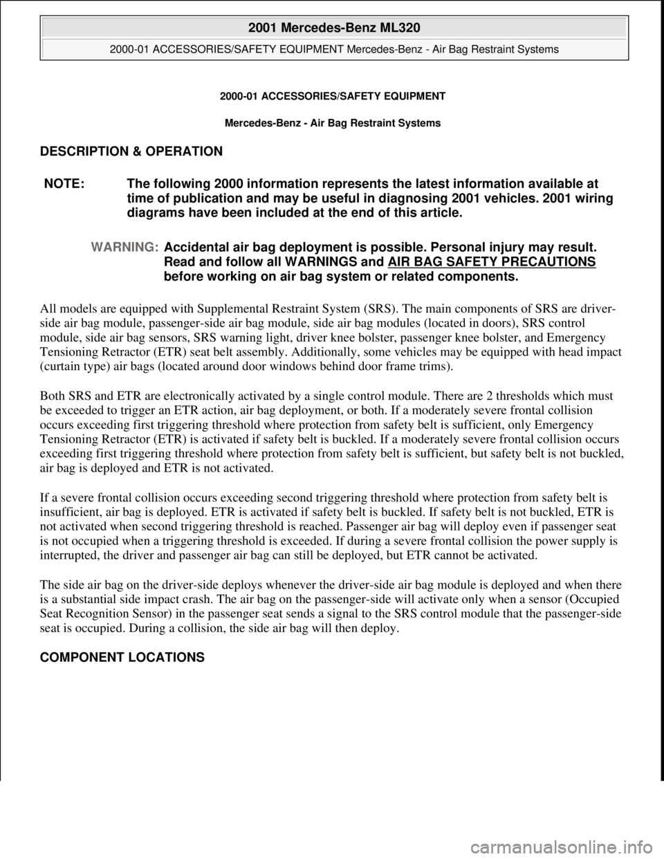
DESCRIPTION & OPERATION
All models are equipped with Supplemental Restraint Syst em (SRS). The main components of SRS are driver-
side air bag module, passenger-side air bag module, si de air bag modules (located in doors), SRS control
module, side air bag sensors, SRS warning light, driver knee bolster, pa ssenger knee bolster, and Emergency
Tensioning Retractor (ETR) seat belt assembly. Additionally, some vehicles may be equipped with head impact
(curtain type) air bags (located ar ound door windows behind door frame trims).
Both SRS and ETR are electronically activated by a single control module. There are 2 thresholds which must
be exceeded to trigger an ETR acti on, air bag deployment, or both. If a moderately severe frontal collision
occurs exceeding first triggering thre shold where protection from safety belt is sufficient, only Emergency
Tensioning Retractor (ETR) is activated if safety belt is buckled. If a moderately severe frontal collision occurs
exceeding first triggering threshold where protection from safety belt is sufficient, but safety belt is not buckled,
air bag is deployed and ETR is not activated.
If a severe frontal collision occurs exceeding second triggering threshold where protection from safety belt is
insufficient, air bag is deploye d. ETR is activated if safety belt is buckled. If safety belt is not buckled, ETR is
not activated when second triggering threshold is reached. Passenger air bag will deploy even if passenger seat
is not occupied when a triggering thre shold is exceeded. If during a severe frontal collision the power supply is
interrupted, the driver and passenger air bag can still be deployed, but ETR cannot be activated.
The side air bag on the driver-side deploys whenever th e driver-side air bag module is deployed and when there
is a substantial side impact crash. The air bag on the pa ssenger-side will activate only when a sensor (Occupied
Seat Recognition Sensor) in the passenger seat sends a si gnal to the SRS control module that the passenger-side
seat is occupied. During a collision, the side air bag will then deploy.
COMPONENT LOCATIONS NOTE: The following 2000 in
formation represents the latest information available at
time of publication and m ay be useful in diagnosing 2001 vehicles. 2001 wiring
diagrams have been included at the end of this article.
WARNING: Accidental air bag deployment is pos sible. Personal injury may result.
Read and follow all WARNINGS and AIR BAG SAFETY PRECAUTIONS
before working on ai r bag system or related components.
2001 Mercedes-Benz ML320
2000-01 ACCESSORIES/SAFETY EQUIPMENT Merc edes-Benz - Air Bag Restraint Systems
2001 Mercedes-Benz ML320
2000-01 ACCESSORIES/SAFETY EQUIPMENT Mercedes-Benz - Air Bag Restraint Systems
me
Saturday, October 02, 2010 3:44:44 PMPage 1 © 2006 Mitchell Repair Information Company, LLC.
me
Saturday, October 02, 2010 3:44:49 PMPage 1 © 2006 Mitchell Repair Information Company, LLC.
Page 374 of 4133
Fig. 2: Removing Side Air Bag Unit (2000 Models)
Courtesy of MERCEDES-BENZ OF NORTH AMERICA.
SIDE AIR BAG SENSOR (DRIVER-SIDE & PASSENGER-SIDE)
Removal & Installation
1. Before proceeding, See AIR BAG SAFETY PRECAUTIONS . Disable air bag system. See
DISABLING & ACTIVATI NG AIR BAG SYSTEM
. Remove ignition key. On SLK 230, remove
door sill moulding. On all models, re move front seat. Fold floor covering in area toward rear. Unclip
connector on side bag sensor. Remove 2 mounting screws. Rem ove sensor from vehicle.
2. To install, reverse removal proce dure. Ensure that arrow on sensor poi nts toward outside. Perform system
operation check to ensure system is functioning properly. See SYSTEM OPERATION CHECK
.
2001 Mercedes-Benz ML320
2000-01 ACCESSORIES/SAFETY EQUIPMENT Merc edes-Benz - Air Bag Restraint Systems
me
Saturday, October 02, 2010 3:44:45 PMPage 10 © 2006 Mitchell Repair Information Company, LLC.
Page 376 of 4133
Fig. 3: Removing Side Air Bag Sensor (2000 E Class Shown; Others Are Similar)
Courtesy of MERCEDES-BENZ OF NORTH AMERICA.
OCCUPIED SEAT RECOGNITION SENSOR
Removal & Installation
1. Before proceeding, See AIR BAG SAFETY PRECAUTIONS . Disable air bag system. See
DISABLING & ACTIVATI NG AIR BAG SYSTEM
.
2. Remove cover on front seat cushion. Remove i gnition key. Unclip connection for occupied seat
recognition sensor on seat connector block. Remove electrical connection lead from seat and pull upward
out of rubberized fiber matting. See Fig. 4
.
3. To install, lay out occupied seat recognition sens or uniformly on rubberized fiber matting. Fabric side
should point upward. Do not kink occupied seat sens or. Reverse removal procedure. Perform system
operation check to ensure s
ystem is functioning properly. See SYSTEM OPERATION CHECK.
2001 Mercedes-Benz ML320
2000-01 ACCESSORIES/SAFETY EQUIPMENT Merc edes-Benz - Air Bag Restraint Systems
me
Saturday, October 02, 2010 3:44:45 PMPage 12 © 2006 Mitchell Repair Information Company, LLC.
Page 377 of 4133

Fig. 4: Removing Occupied Seat Recognition Sensor (2000 Models)
Courtesy of MERCEDES-BENZ OF NORTH AMERICA.
PASSENGER-SIDE AIR BAG MODULE
Removal & Installation (C Class)
1. Before proceeding, See AIR BAG SAFETY PRECAUTIONS . Disable air bag system. See
DISABLING & ACTIVATI NG AIR BAG SYSTEM
. Remove ignition key. Remove instrument panel.
2001 Mercedes-Benz ML320
2000-01 ACCESSORIES/SAFETY EQUIPMENT Merc edes-Benz - Air Bag Restraint Systems
me
Saturday, October 02, 2010 3:44:45 PMPage 13 © 2006 Mitchell Repair Information Company, LLC.
Page 385 of 4133
module. If HHT displays an "F", go to step 3.2.
Read TEST CONNECTION (NOT FOR HHT) column. Horn -air bag clockspring connector A45x1, terminals
No. 1 and 2 are identified. Read TEST CONDITION column. Test circuit with HHT connected to DLC.
Remove ignition key. Connect Resist ance Substitution Unit (124 589 09 63 00) to horn-air bag clockspring
connector A45x1. Set resistance s ubstitution unit to 2 ohms. Read NOMINAL VALUE-HHT DISPLAY
column. If HHT displays a check, check horn-air ba g clockspring for continuity. Replace horn-air bag
clockspring as necessary. If HHT displays an "F", go to step 3.4.
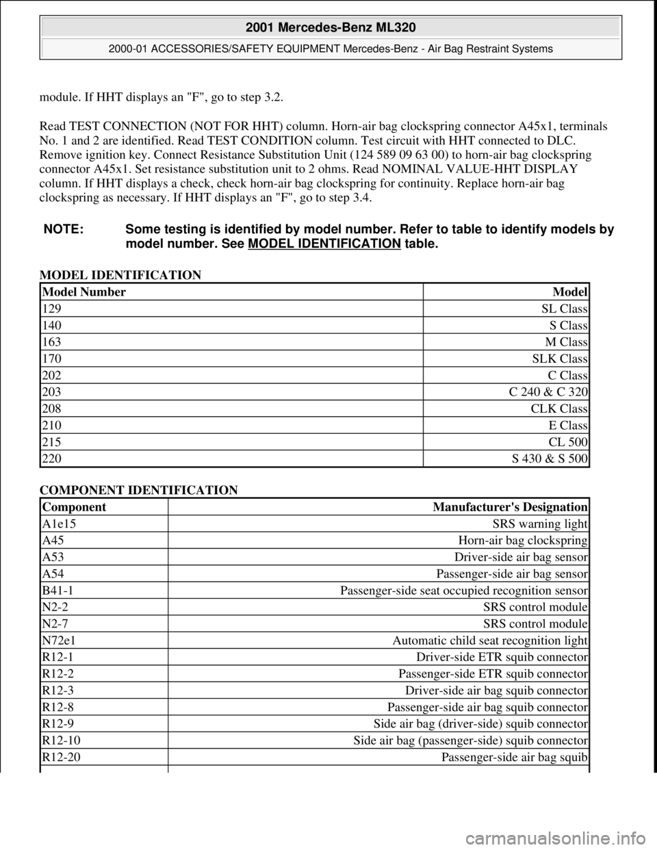
MODEL IDENTIFICATION
COMPONENT IDENTIFICATION
NOTE: Some testing is identified
by model number. Refer to table to identify models by
model number. See MO DEL IDENTIFICATION
table.
Model NumberModel
129SL Class
140S Class
163M Class
170SLK Class
202C Class
203C 240 & C 320
208CLK Class
210E Class
215CL 500
220S 430 & S 500
ComponentManufacturer's Designation
A1e15SRS warning light
A45Horn-air bag clockspring
A53Driver-side air bag sensor
A54Passenger-side air bag sensor
B41-1Passenger-side seat occupied recognition sensor
N2-2SRS control module
N2-7SRS control module
N72e1Automatic child seat recognition light
R12-1Driver-side ETR squib connector
R12-2Passenger-side ETR squib connector
R12-3Driver-side air bag squib connector
R12-8Passenger-side air bag squib connector
R12-9Side air bag (driver-side) squib connector
R12-10Side air bag (passenge r-side) squib connector
R12-20Passenger-side air bag squib
2001 Mercedes-Benz ML320
2000-01 ACCESSORIES/SAFETY EQUIPMENT Merc edes-Benz - Air Bag Restraint Systems
me
Saturday, October 02, 2010 3:44:46 PMPage 21 © 2006 Mitchell Repair Information Company, LLC.