1997 MERCEDES-BENZ ML350 hood release
[x] Cancel search: hood releasePage 2516 of 4133
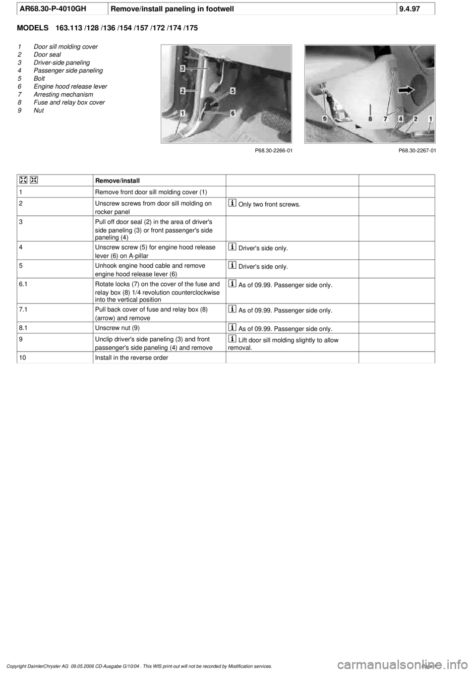
AR68.30-P-4010GHRemove/install paneling in footwell
9.4.97
MODELS
163.113 /128 /136 /154 /157 /172 /174 /175
P68.30-2266-01
1
Door sill molding cover
2
Door seal
3
Driver-side paneling
4
Passenger side paneling
5
Bolt
6
Engine hood release lever
7
Arresting mechanism
8
Fuse and relay box cover
9
Nut
P68.30-2267-01
Remove/install
1
Remove front door sill molding cover (1)
2
Unscrew screws from door sill molding on
rocker panel
Only two front screws.
3
Pull off door seal (2) in the area of driver's
side paneling (3) or front passenger's side
paneling (4)
4
Unscrew screw (5) for engine hood release
lever (6) on A-pillar
Driver's side only.
5
Unhook engine hood cable and remove
engine hood release lever (6)
Driver's side only.
6.1
Rotate locks (7) on the cover of the fuse and
relay box (8) 1/4 revolution counterclockwise
into the vertical position
As of 09.99. Passenger side only.
7.1
Pull back cover of fuse and relay box (8)
(arrow) and remove
As of 09.99. Passenger side only.
8.1
Unscrew nut (9)
As of 09.99. Passenger side only.
9
Unclip driver's side paneling (3) and front
passenger's side paneling (4) and remove
Lift door sill molding slightly to allow
removal.
10
Install in the reverse order
Copyright DaimlerChrysler AG 09.05.2006 CD-Ausgabe G/10/04 . This WIS print-out will not be recorde
d by Modification services.
Page 1
Page 2583 of 4133
AR07.16-P-1100MM
Remove, install fuel cooler
5.11.99
ENGINE
612.963 in MODELS 163.113
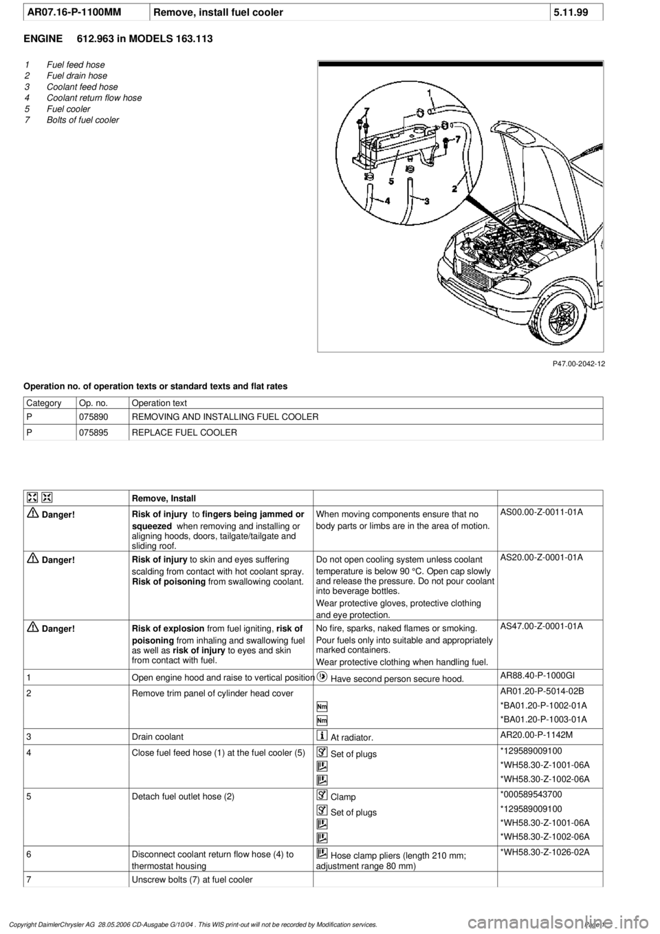
P47.00-2042-12
1
Fuel feed hose
2
Fuel drain hose
3
Coolant feed hose
4
Coolant return flow hose
5
Fuel cooler
7
Bolts of fuel cooler
Operation no. of operation texts or standard texts and flat rates
Category
Op. no.
Operation text
P
075890
REMOVING AND INSTALLING FUEL COOLER
P
075895
REPLACE FUEL COOLER
Remove, Install
Danger!
Risk of injury
to
fingers being jammed or
squeezed
when removing and installing or
aligning hoods, doors, tailgate/tailgate and
sliding roof.
When moving components ensure that no
body parts or limbs are in the area of motion.
AS00.00-Z-0011-01A
Danger!
Risk of injury
to skin and eyes suffering
scalding from contact with hot coolant spray.
Risk of poisoning
from swallowing coolant.
Do not open cooling system unless coolant
temperature is below 90 °C. Open cap slowly
and release the pressure. Do not pour coolant
into beverage bottles.
Wear protective gloves, protective clothing
and eye protection.
AS20.00-Z-0001-01A
Danger!
Risk of explosion
from fuel igniting,
risk of
poisoning
from inhaling and swallowing fuel
as well as
risk of injury
to eyes and skin
from contact with fuel.
No fire, sparks, naked flames or smoking.
Pour fuels only into suitable and appropriately
marked containers.
Wear protective clothing when handling fuel.
AS47.00-Z-0001-01A
1
Open engine hood and raise to vertical position
Have second person secure hood.
AR88.40-P-1000GI
2
Remove trim panel of cylinder head cover
AR01.20-P-5014-02B
*BA01.20-P-1002-01A
*BA01.20-P-1003-01A
3
Drain coolant
At radiator.
AR20.00-P-1142M
4
Close fuel feed hose (1) at the fuel cooler (5)
Set of plugs
*129589009100
*WH58.30-Z-1001-06A
*WH58.30-Z-1002-06A
5
Detach fuel outlet hose (2)
Clamp
*000589543700
Set of plugs
*129589009100
*WH58.30-Z-1001-06A
*WH58.30-Z-1002-06A
6
Disconnect coolant return flow hose (4) to
thermostat housing
Hose clamp pliers (length 210 mm;
adjustment range 80 mm)
*WH58.30-Z-1026-02A
7
Unscrew bolts (7) at fuel cooler
Copyright DaimlerChrysler AG 28.05.2006 CD-Ausgabe G/10/04 . This WIS print-out will not be recorde
d by Modification services.
Page 1
Page 3194 of 4133
15
Adjust gap dimensions
Gap dimensions
*BE60.00-P-1001-01D
Feeler gage
*129589032100
16
Align engine hood catch upper section (5)
centered in longitudinal and transverse
direction to engine hood catch lower section
and tighten
*BA88.40-P-1004-01C
17
Ensure that engine hood catch catches
properly
For this purpose, close engine hood and
pull upward with a jerk.
18
Release engine hood and ensure that safety
hook catches on radiator crossmember
19
Close engine hood (2)
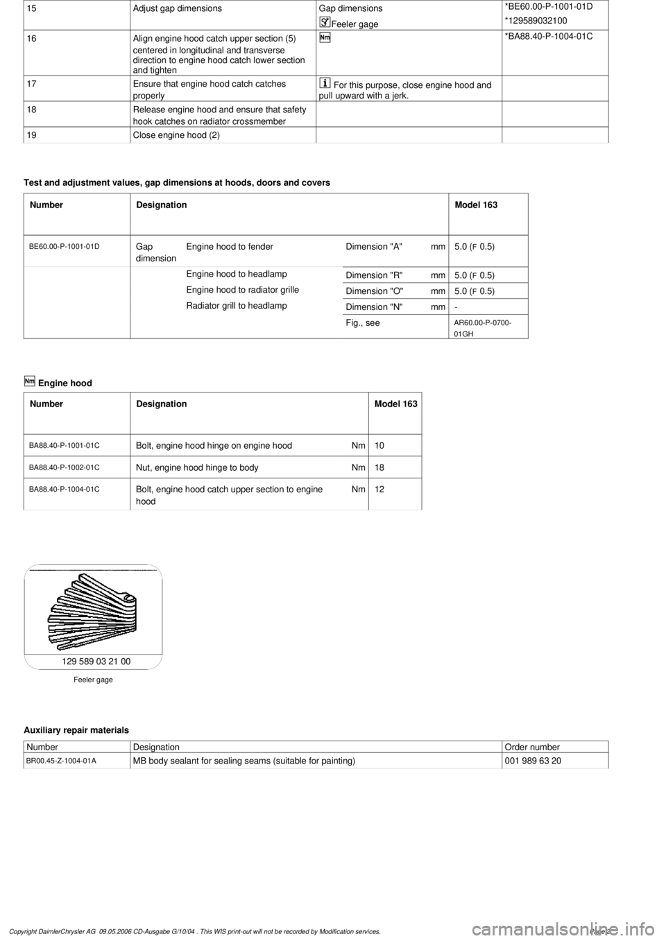
Test and adjustment values, gap dimensions at hoods, doors and covers
Number
Designation
Model 163
BE60.00-P-1001-01D
Gap
dimension
Engine hood to fender
Dimension "A"
mm
5.0 (
F
0.5)
Engine hood to headlamp
Dimension "R"
mm
5.0 (
F
0.5)
Engine hood to radiator grille
Dimension "O"
mm
5.0 (
F
0.5)
Radiator grill to headlamp
Dimension "N"
mm
-
Fig., see
AR60.00-P-0700-
01GH
Engine hood
Number
Designation
Model 163
BA88.40-P-1001-01C
Bolt, engine hood hinge on engine hood
Nm
10
BA88.40-P-1002-01C
Nut, engine hood hinge to body
Nm
18
BA88.40-P-1004-01C
Bolt, engine hood catch upper section to engine
hood
Nm
12
129 589 03 21 00
Feeler gage
Auxiliary repair materials
Number
Designation
Order number
BR00.45-Z-1004-01A
MB body sealant for sealing seams (suitable for painting)
001 989 63 20
Copyright DaimlerChrysler AG 09.05.2006 CD-Ausgabe G/10/04 . This WIS print-out will not be recorde
d by Modification services.
Page 2
Page 3196 of 4133
15
Adjust gap dimensions
Gap dimensions
*BE60.00-P-1001-01D
Feeler gage
*129589032100
16
Align engine hood catch upper section (5)
centered in longitudinal and transverse
direction to engine hood catch lower section
and tighten
*BA88.40-P-1004-01C
17
Ensure that engine hood catch catches
properly
For this purpose, close engine hood and
pull upward with a jerk.
18
Release engine hood and ensure that safety
hook catches on radiator crossmember
19
Close engine hood (2)
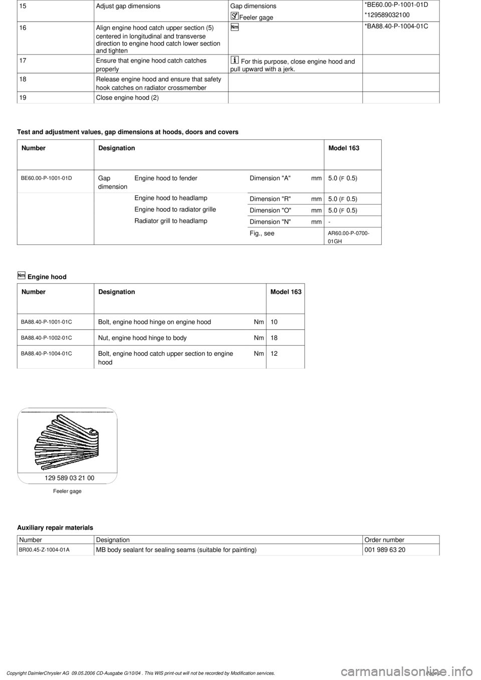
Test and adjustment values, gap dimensions at hoods, doors and covers
Number
Designation
Model 163
BE60.00-P-1001-01D
Gap
dimension
Engine hood to fender
Dimension "A"
mm
5.0 (
F
0.5)
Engine hood to headlamp
Dimension "R"
mm
5.0 (
F
0.5)
Engine hood to radiator grille
Dimension "O"
mm
5.0 (
F
0.5)
Radiator grill to headlamp
Dimension "N"
mm
-
Fig., see
AR60.00-P-0700-
01GH
Engine hood
Number
Designation
Model 163
BA88.40-P-1001-01C
Bolt, engine hood hinge on engine hood
Nm
10
BA88.40-P-1002-01C
Nut, engine hood hinge to body
Nm
18
BA88.40-P-1004-01C
Bolt, engine hood catch upper section to engine
hood
Nm
12
129 589 03 21 00
Feeler gage
Auxiliary repair materials
Number
Designation
Order number
BR00.45-Z-1004-01A
MB body sealant for sealing seams (suitable for painting)
001 989 63 20
Copyright DaimlerChrysler AG 09.05.2006 CD-Ausgabe G/10/04 . This WIS print-out will not be recorde
d by Modification services.
Page 2
Page 3208 of 4133
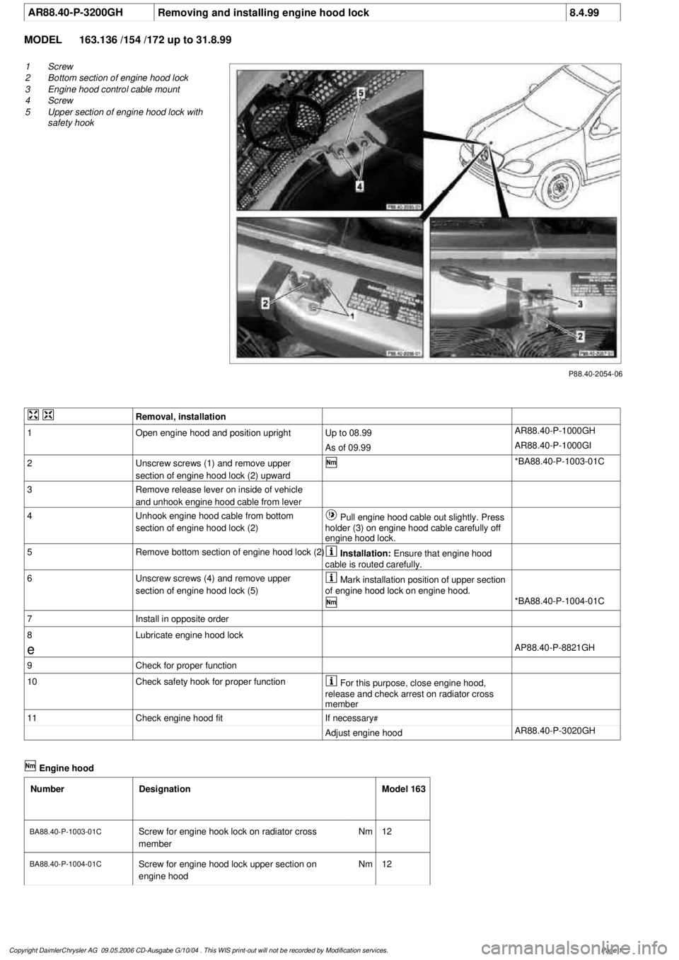
AR88.40-P-3200GH
Removing and installing engine hood lock
8.4.99
MODEL
163.136 /154 /172 up to 31.8.99
P88.40-2054-06
1
Screw
2
Bottom section of engine hood lock
3
Engine hood control cable mount
4
Screw
5
Upper section of engine hood lock with
safety hook
Removal, installation
1
Open engine hood and position upright
Up to 08.99
AR88.40-P-1000GH
As of 09.99
AR88.40-P-1000GI
2
Unscrew screws (1) and remove upper
section of engine hood lock (2) upward
*BA88.40-P-1003-01C
3
Remove release lever on inside of vehicle
and unhook engine hood cable from lever
4
Unhook engine hood cable from bottom
section of engine hood lock (2)
Pull engine hood cable out slightly. Press
holder (3) on engine hood cable carefully off
engine hood lock.
5
Remove bottom section of engine hood lock (2)
Installation:
Ensure that engine hood
cable is routed carefully.
6
Unscrew screws (4) and remove upper
section of engine hood lock (5)
Mark installation position of upper section
of engine hood lock on engine hood.
*BA88.40-P-1004-01C
7
Install in opposite order
8
Lubricate engine hood lock
e
AP88.40-P-8821GH
9
Check for proper function
10
Check safety hook for proper function
For this purpose, close engine hood,
release and check arrest on radiator cross
member
11
Check engine hood fit
If necessary
#
Adjust engine hood
AR88.40-P-3020GH
Engine hood
Number
Designation
Model 163
BA88.40-P-1003-01C
Screw for engine hook lock on radiator cross
member
Nm
12
BA88.40-P-1004-01C
Screw for engine hood lock upper section on
engine hood
Nm
12
Copyright DaimlerChrysler AG 09.05.2006 CD-Ausgabe G/10/04 . This WIS print-out will not be recorde
d by Modification services.
Page 1
Page 3232 of 4133
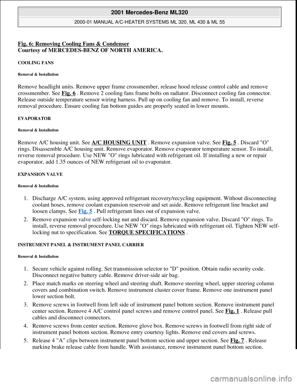
Fig. 6: Removing Cooling Fans & Condenser
Courtesy of MERCEDES-BENZ OF NORTH AMERICA.
COOLING FANS
Removal & Installation
Remove headlight units. Remove upper frame crossmember, release hood release control cable and remove
crossmember. See Fig. 6
. Remove 2 cooling fans frame bolts on radiator. Disconnect cooling fan connector.
Release outside temperature sensor wiring harness. Pull up on cooling fan and remove. To install, reverse
removal procedure. Ensure cooling fan bottom guides are properly seated in lower mounts.
EVAPORATOR
Removal & Installation
Remove A/C housing unit. See A/C HOUSING UNIT . Remove expansion valve. See Fig. 5 . Discard "O"
rings. Disassemble A/C housing unit. Remove evaporator. Remove evaporator temperature sensor. To install,
reverse removal procedure. Use NEW "O" rings lubricated with refrigerant oil. If installing a new or repair
evaporator, add 1.35 ounces of NEW refrigerant oil to evaporator.
EXPANSION VALVE
Removal & Installation
1. Discharge A/C system, using approved refrigerant recovery/recycling equipment. Without disconnecting
coolant hoses, remove coolant expansion reservoir and set aside. Remove refrigerant line bracket and
loosen clamps. See Fig. 5
. Pull refrigerant lines out of expansion valve.
2. Remove expansion valve self-locking nut and discard. Remove expansion valve. Discard "O" rings. To
install, reverse removal procedure. Use NEW "O" rings lubricated with refrigerant oil. Tighten NEW self-
locking nut to specification. See TORQUE SPECIFICATIONS
.
INSTRUMENT PANEL & INSTRUMENT PANEL CARRIER
Removal & Installation
1. Secure vehicle against rolling. Set transmission selector to "D" position. Obtain radio security code.
Disconnect negative battery cable. Remove driver-side air bag.
2. Place match marks on steering wheel and steering shaft. Remove steering wheel, upper steering column
covers and combination switch. Remove instrument cluster cover frame. Remove one instrument panel
lower section bolt.
3. Remove screws in footwell from left side of instrument panel bottom section. Remove instrument panel
center section. Remove 4 A/C control panel screws and remove control panel. See Fig. 1
. Release pull
cables and disconnect connectors.
4. Remove screws from center section. Remove glove box. Remove screws in footwell from right side of
instrument panel bottom section. Remove entry courtesy lights. Remove end covers and screws.
5. Release 4 "A" clips between instrument panel bottom section and upper section. See Fig. 7
. Release
parkin
g brake release cable from handle. With assistance, remove instrument panel bottom section.
2001 Mercedes-Benz ML320
2000-01 MANUAL A/C-HEATER SYSTEMS ML 320, ML 430 & ML 55
me
Saturday, October 02, 2010 3:25:10 PMPage 21 © 2006 Mitchell Repair Information Company, LLC.
Page 3236 of 4133
Fig. 9: Replacing Intake Air Dust Filter
Courtesy of MERCEDES-BENZ OF NORTH AMERICA.
RECEIVER-DRIER
Removal & Installation
1. Discharge A/C system, using approved refrigerant recovery/recycling equipment. Remove headlight
units. Remove headlight units. Remove upper frame crossmember, release hood release control cable and
remove crossmember. See Fig. 6
.
2. Remove bolts from receiver-drier refrigerant lines. See Fig. 5
. Disconnect refrigerant lines from receiver-
drier. Plug exposed openings to protect A/C system from debris and moisture. Discard "O" rings. Loosen
receiver-drier clamp bolt. Remove receiver-drier. To install, reverse removal procedure.
3. When installing a new receiver-drier, add 0.34 ounce of NEW refrigerant oil to receiver-drier. Use NEW
"O" rings. Tighten refrigerant line bolts to specification. See TORQUE SPECIFICATIONS
.
TORQUE SPECIFICATIONS
TORQUE SPECIFICATIONS
WIRING DIAGRAMS
ApplicationFt. Lbs. (N.m)
Compressor Mounting Bolts15 (20)
Refrigerant Line-To-Compressor Bolt15 (20)
Refrigerant Line-To-Condenser Bolt15 (20)
Steering Column Bolt15 (20)
Steering Column Nut13 (18)
INCH Lbs. (N.m)
Expansion Valve Self-Locking Nut89 (10)
Refrigerant Line-To-Receiver-Drier Bolt89 (10)
2001 Mercedes-Benz ML320
2000-01 MANUAL A/C-HEATER SYSTEMS ML 320, ML 430 & ML 55
me
Saturday, October 02, 2010 3:25:10 PMPage 25 © 2006 Mitchell Repair Information Company, LLC.
Page 3576 of 4133
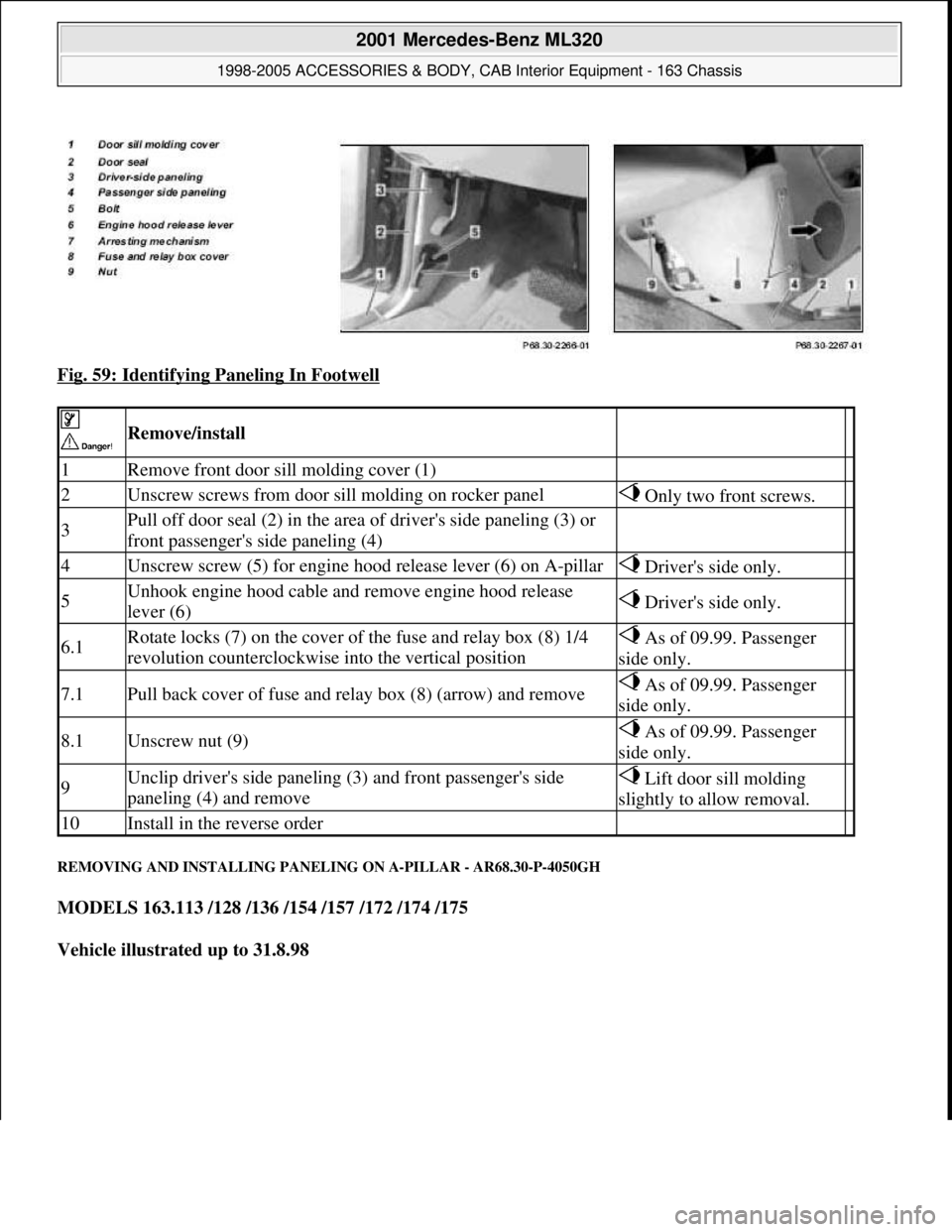
Fig. 59: Identifying Paneling In Footwell
REMOVING AND INSTALLING PANELING ON A-PILLAR - AR68.30-P-4050GH
MODELS 163.113 /128 /136 /154 /157 /172 /174 /175
Vehicle illustrated up to 31.8.98
Remove/install
1Remove front door sill molding cover (1)
2Unscrew screws from door sill molding on rocker panel Only two front screws.
3Pull off door seal (2) in the area of driver's side paneling (3) or
front passenger's side paneling (4)
4Unscrew screw (5) for engine hood release lever (6) on A-pillar Driver's side only.
5Unhook engine hood cable and remove engine hood release
lever (6) Driver's side only.
6.1Rotate locks (7) on the cover of the fuse and relay box (8) 1/4
revolution counterclockwise into the vertical position As of 09.99. Passenger
side only.
7.1Pull back cover of fuse and relay box (8) (arrow) and remove As of 09.99. Passenger
side only.
8.1Unscrew nut (9) As of 09.99. Passenger
side only.
9Unclip driver's side paneling (3) and front passenger's side
paneling (4) and remove Lift door sill molding
slightly to allow removal.
10Install in the reverse order
2001 Mercedes-Benz ML320
1998-2005 ACCESSORIES & BODY, CAB Interior Equipment - 163 Chassis
me
Saturday, October 02, 2010 3:35:22 PMPage 58 © 2006 Mitchell Repair Information Company, LLC.