1997 MERCEDES-BENZ ML320 timing chain
[x] Cancel search: timing chainPage 2088 of 4133

16
Remove poly V-belt (8)
Installation:
Lock tensioning device with
a drift or pin (diameter 5 mm).
Model 163.154 /157 /172.
AR13.22-P-1202B
Model 163.174 /175.
AR13.22-P-1202BA
17
Detach the coolant line (16) at the cylinder
head on the left
6 mm socket hexagon
*WH58.30-Z-1001-06A
7 mm socket hexagon
*WH58.30-Z-1002-06A
18.1
Remove fender liner (9)
Only with engine 113.113.942 /965 / 981.
AR88.10-P-1300GH
19.1
Remove shield (10)
Only with engine 113.942 /965 /981.
20.1
Remove exhaust bracket (11)
Only with engine 113.942 /965 /981.
Support exhaust system.
21
Detach exhaust system at exhaust manifold
Installation:
On vehicles with engine
damage, the exhaust system must be
examined for swarfs before assembling and
any swarfs present must be removed, in order
to avoid consequential damage.
*BA14.10-P-1002-01B
22
Position crankshaft to 40° after ignition TDC
on cylinder 1
The engine must not be turned back;
otherwise the timing chain can get jammed.
AR05.10-P-6858V
Rotate engine at the crankshaft in running
direction until scribe mark 40° on pulley/
vibration damper corresponds with scribe
mark on timing case.
The grooves on the camshafts must be
pointing toward the inner V.
23
Lock camshafts with locating plates
Locating plate
*112589003200
Locating plate
*112589013200
24
Remove chain tensioner (17)
Model 163.154 /157 with engine 112.942/
970, model 163.172 with engine 113.942.
AR05.10-P-7800C
Model 163.174 /175 with engine 113.981/ 965.
AR05.10-P-7800CA
25.1
Remove oil filter housing (18) together with oil-
water heat exchanger
Engine 113.942.
AR18.20-P-3471B
Engine 112.942/970.
AR18.20-P-3471BA
26
Unscrew camshaft sprockets (19)
If camshaft sprockets are removed,
engine must no longer be cranked, otherwise
timing chain might jam.
Engine 113.942 /965 /981:
#
Tie timing chain tight on both camshaft
sprockets with tie straps.
Engine 112.942 /970:
#
Right-hand camshaft sprocket:
Tie timing chain tight on camshaft sprocket
with tie strap.
Left-hand camshaft sprocket:
Mark camshaft sprocket to timing chain and
remove camshaft sprocket.
It is not possible for the timing chain to
jump across at the crankshaft and balancing
shaft.
After installation:
#
Inspect basic position of camshafts.
AR05.10-P-6858V
If necessary after checking:
#
Set the basic position of camshafts
AR05.20-P-6020AU
Open-end wrench
*112589000100
Insertion tool
*112589010300
Torque wrench
*001589722100
*BA05.20-P-1001-01B
27
Remove camshaft bearing bridges (28)
Pay attention to slackening and tightening
pattern!
AR05.20-P-7103AU
28
Unscrew bolts, cylinder head
!
timing case
cover (20)
*BA01.40-P-1002-01C
Copyright DaimlerChrysler AG 20.05.2006 CD-Ausgabe G/10/04 . This WIS print-out will not be recorde
d by Modification services.
Page 4
Page 2096 of 4133

16
Remove poly V-belt (8)
Installation:
Lock tensioning device with
a drift or pin (diameter 5 mm).
Model 163.154 /157 /172.
AR13.22-P-1202B
Model 163.174 /175.
AR13.22-P-1202BA
17
Detach the coolant line (16) at the cylinder
head on the left
6 mm socket hexagon
*WH58.30-Z-1001-06A
7 mm socket hexagon
*WH58.30-Z-1002-06A
18.1
Remove fender liner (9)
Only with engine 113.113.942 /965 / 981.
AR88.10-P-1300GH
19.1
Remove shield (10)
Only with engine 113.942 /965 /981.
20.1
Remove exhaust bracket (11)
Only with engine 113.942 /965 /981.
Support exhaust system.
21
Detach exhaust system at exhaust manifold
Installation:
On vehicles with engine
damage, the exhaust system must be
examined for swarfs before assembling and
any swarfs present must be removed, in order
to avoid consequential damage.
*BA14.10-P-1002-01B
22
Position crankshaft to 40° after ignition TDC
on cylinder 1
The engine must not be turned back;
otherwise the timing chain can get jammed.
AR05.10-P-6858V
Rotate engine at the crankshaft in running
direction until scribe mark 40° on pulley/
vibration damper corresponds with scribe
mark on timing case.
The grooves on the camshafts must be
pointing toward the inner V.
23
Lock camshafts with locating plates
Locating plate
*112589003200
Locating plate
*112589013200
24
Remove chain tensioner (17)
Model 163.154 /157 with engine 112.942/
970, model 163.172 with engine 113.942.
AR05.10-P-7800C
Model 163.174 /175 with engine 113.981/ 965.
AR05.10-P-7800CA
25.1
Remove oil filter housing (18) together with oil-
water heat exchanger
Engine 113.942.
AR18.20-P-3471B
Engine 112.942/970.
AR18.20-P-3471BA
26
Unscrew camshaft sprockets (19)
If camshaft sprockets are removed,
engine must no longer be cranked, otherwise
timing chain might jam.
Engine 113.942 /965 /981:
#
Tie timing chain tight on both camshaft
sprockets with tie straps.
Engine 112.942 /970:
#
Right-hand camshaft sprocket:
Tie timing chain tight on camshaft sprocket
with tie strap.
Left-hand camshaft sprocket:
Mark camshaft sprocket to timing chain and
remove camshaft sprocket.
It is not possible for the timing chain to
jump across at the crankshaft and balancing
shaft.
After installation:
#
Inspect basic position of camshafts.
AR05.10-P-6858V
If necessary after checking:
#
Set the basic position of camshafts
AR05.20-P-6020AU
Open-end wrench
*112589000100
Insertion tool
*112589010300
Torque wrench
*001589722100
*BA05.20-P-1001-01B
27
Remove camshaft bearing bridges (28)
Pay attention to slackening and tightening
pattern!
AR05.20-P-7103AU
28
Unscrew bolts, cylinder head
!
timing case
cover (20)
*BA01.40-P-1002-01C
Copyright DaimlerChrysler AG 20.05.2006 CD-Ausgabe G/10/04 . This WIS print-out will not be recorde
d by Modification services.
Page 4
Page 2239 of 4133

AF07.00-P-9000B
Engine runs rough, surges or does not turn over
29.4.02
ENGINE
611 in MODEL 203, 202, 210
ENGINE
612 in MODEL 163, 203, 210, 209
ENGINE
613 in MODEL 210, 220
ENGINE
628 in MODEL 163, 220, 211
ENGINE
646 in MODEL 203, 211
ENGINE
647 in MODEL 211
ENGINE
648 in MODEL 220, 211
ENGINE
668 in MODEL 168
ENGINE
612, 628 in MODEL 463
Modification notes
23.3.01
Supersedes STIP 07.16-014 dated 11.12.00
Damage code
Cause
Remedy
07 206 D5
High-pressure pump
To verify whether high pressure pump is
damaged.
#
High pressure pump of common rail
injection system is damaged mechanically.
1
Remove/install/replace high pressure
pump.
When the high pressure pump of the common
rail injection system is damaged metal chips
and/or damage to the pump drive (timing
drive) can occur due to contamination of the
injection system components.
2
Turn high pressure pump by hand with
driver.
If mechanical resistance can be felt,
perform the following tests. Clarify additional
work with ESKULAB by specifying repair work:
#
3
Check driver of high pressure pump or
mount in sprocket for damage (visual
check).
If high pressure pump is locked:
#
4
Check timing
5
Check timing drive for damage.
In each case:
#
6
Remove/install/replace timing chain.
If timing deviates by a crankshaft angle of
more than 20 degrees (corresponding to one
tooth skipped):
#
7
Check pressure loss.
8
Open low pressure connection on high
pressure pump return (plastic line in
area of pressure regulator valve) and
check connection point in rail for chips.
If chips are present when checking
injection system:
#
9
Thoroughly clean all fuel low pressure
lines as well as feed and return lines.
Flush and blow out with compressed air.
10
Remove fuel preheater and fuel filter
with filter housing, replace.
Fuel preheater is only installed in models
202, 203 and 163.
11
Remove/install/replace fuel cooler at
vehicle and engine end.
Not installed in model 210 up to 6/99 and
model 168.
12
Remove fuel tank, replace.
On engine 628:
#
13
Remove/install/replace electric supply
pump.
14
Remove/install/replace injectors, rail
(including pressure regulation valve and
rail pressure sensor), high pressure
lines and injector leak oil rail.*
Copyright DaimlerChrysler AG 28.05.2006 CD-Ausgabe G/10/04 . This WIS print-out will not be recorde
d by Modification services.
Page 1
Page 2243 of 4133
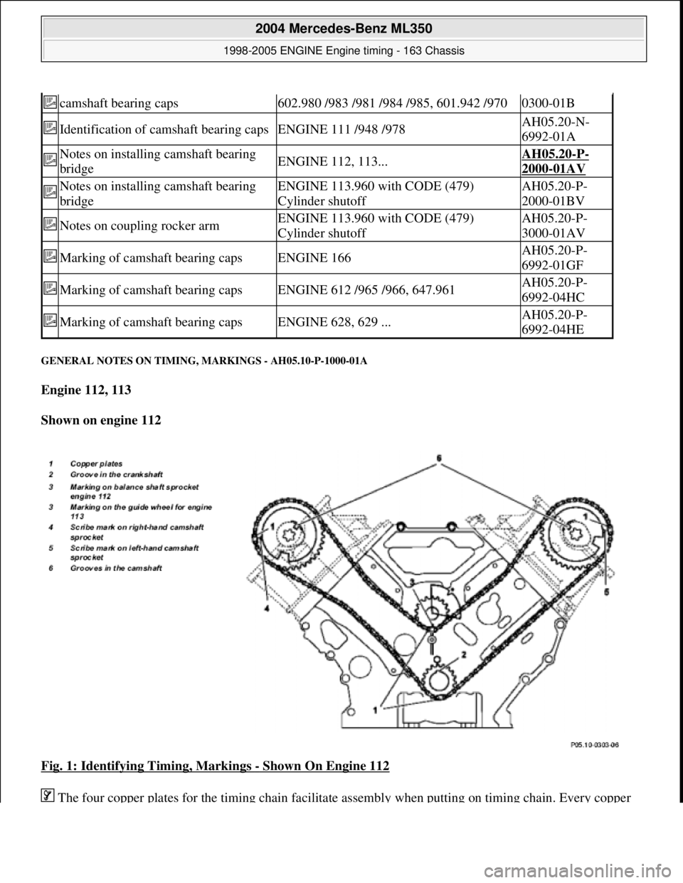
GENERAL NOTES ON TIMING, MARKINGS - AH05.10-P-1000-01A
Engine 112, 113
Shown on engine 112
Fig. 1: Identifying Timing, Markings
- Shown On Engine 112
The four copper plates for the timin
g chain facilitate assembly when putting on timing chain. Every copper
camshaft bearing caps602.980 /983 /981 /984 /985, 601.942 /9700300-01B
Identification of camshaft bearing capsENGINE 111 /948 /978AH05.20-N-
6992-01A
Notes on installing camshaft bearing
bridgeENGINE 112, 113...AH05.20-P-
2000-01AV
Notes on installing camshaft bearing
bridgeENGINE 113.960 with CODE (479)
Cylinder shutoffAH05.20-P-
2000-01BV
Notes on coupling rocker armENGINE 113.960 with CODE (479)
Cylinder shutoffAH05.20-P-
3000-01AV
Marking of camshaft bearing capsENGINE 166AH05.20-P-
6992-01GF
Marking of camshaft bearing capsENGINE 612 /965 /966, 647.961AH05.20-P-
6992-04HC
Marking of camshaft bearing capsENGINE 628, 629 ...AH05.20-P-
6992-04HE
2004 Mercedes-Benz ML350
1998-2005 ENGINE Engine timing - 163 Chassis
me
Saturday, October 02, 2010 3:39:37 PMPage 2 © 2006 Mitchell Repair Information Company, LLC.
Page 2245 of 4133
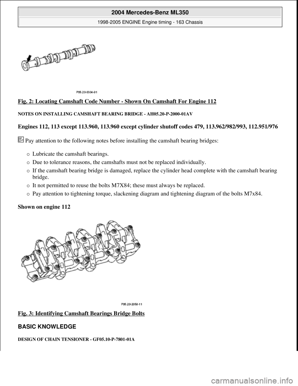
Fig. 2: Locating Camshaft Code Number - Shown On Camshaft For Engine 112
NOTES ON INSTALLING CAMSHAFT BEARING BRIDGE - AH05.20-P-2000-01AV
Engines 112, 113 except 113.960, 113.960 except cylind er shutoff codes 479, 113.962/982/993, 112.951/976
Pay attention to the following notes before installing the camshaft bearing bridges:
Lubricate the camshaft bearings.
Due to tolerance reasons, the camshafts must not be replaced individually.
If the camshaft bearing bridge is damaged, replace th e cylinder head complete with the camshaft bearing
bridge.
It not permitted to reuse the bolts M7 X84; these must always be replaced.
Pay attention to tightening torque, slackening di agram and tightening diagram of the bolts M7x84.
Shown on engine 112
Fig. 3: Identifying Camshaft Bearings Bridge Bolts
BASIC KNOWLEDGE
DESIGN OF CHAIN TENS IONER - GF05.10-P-7801-01A
2004 Mercedes-Benz ML350
1998-2005 ENGINE Engine timing - 163 Chassis
me
Saturday, October 02, 2010 3:39:37 PMPage 4 © 2006 Mitchell Repair Information Company, LLC.
Page 2246 of 4133
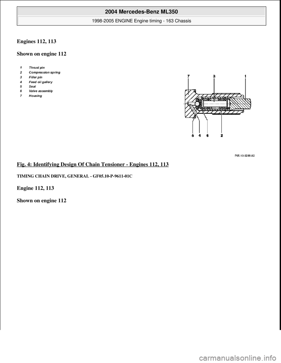
Engines 112, 113
Shown on engine 112
Fig. 4: Identifying Desi gn Of Chain Tensioner
- Engines 112, 113
TIMING CHAIN DRIVE, GENERAL - GF05.10-P-9611-01C
Engine 112, 113
Shown on engine 112
2004 Mercedes-Benz ML350
1998-2005 ENGINE Engine timing - 163 Chassis
me
Saturday, October 02, 2010 3:39:37 PMPage 5 © 2006 Mitchell Repair Information Company, LLC.
Page 2247 of 4133
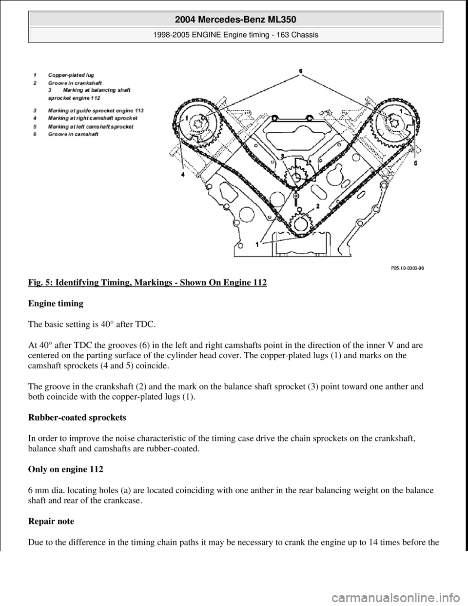
Fig. 5: Identifying Timing, Markings - Shown On Engine 112
Engine timing
The basic setting is 40° after TDC.
At 40° after TDC the grooves (6) in th e left and right camshafts point in the direction of the inner V and are
centered on the parting surface of the cylinder head cover. The copper-plated lugs (1) and marks on the
camshaft sprockets (4 and 5) coincide.
The groove in the crankshaft (2) and the mark on the ba lance shaft sprocket (3) point toward one anther and
both coincide with the copper-plated lugs (1).
Rubber-coated sprockets
In order to improve the noise characteristic of the timing case drive the chain sprockets on the crankshaft,
balance shaft and camshafts are rubber-coated.
Only on engine 112
6 mm dia. locating holes (a) are located coinciding with one anther in the rear balancing weight on the balance
shaft and rear of the crankcase.
Repair note
Due to the difference in the timin
g chain paths it may be necessary to crank the engine up to 14 times before the
2004 Mercedes-Benz ML350
1998-2005 ENGINE Engine timing - 163 Chassis
me
Saturday, October 02, 2010 3:39:37 PMPage 6 © 2006 Mitchell Repair Information Company, LLC.
Page 2251 of 4133
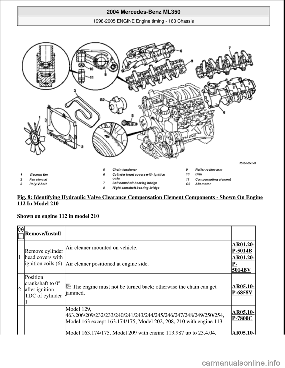
Fig. 8: Identifying Hydraulic Valve Clea rance Compensation Element Components - Shown On Engine
112 In Model 210
Shown on engine 112 in model 210
Remove/Install
1
Remove cylinder
head covers with
ignition coils (6)Air cleaner mounted on vehicle.AR01.20-
P-5014B
Air cleaner positione d at engine side.
AR01.20-
P-
5014BV
2
Position
crankshaft to 0°
after ignition
TDC of cylinder
1
The engine must not be turned back; otherwise the chain can get
jammed.
AR05.10-
P-6858V
Model 129,
463.206/209/232/233/240/241/243/2 44/245/246/247/248/249/250/254,
Model 163 except 163.174/175, Model 202, 208, 210 with engine 113AR05.10-
P-7800C
Model 163.174/175, Model 209 with engine 113.987 up to 23.4.04, AR05.10-
2004 Mercedes-Benz ML350
1998-2005 ENGINE Engine timing - 163 Chassis
me
Saturday, October 02, 2010 3:39:37 PMPage 10 © 2006 Mitchell Repair Information Company, LLC.