Page 2261 of 4133
Fig. 18: Identifying Chain Separating Tool, P ressure Screw, Guide Sleeve And Timing Chain
RIVET TIMING CHAIN - AR05.10-P-7601-02AV
Camshaft
Camshaft
Camshaft
NumberDesignationEngine 112
except
112.951/976Engine
112.951/976
BA05.20-P-
1001-01BBolt for
camshaft
sprocketM12x45Stage 1Nm5050
Stage 2Angle°9090
NumberDesignationEngines
113.940/941/942/943/944/948/961/9 62/963/964/965/966/967/968/96
9
BA05.20-
P-1001-
01BBolt for
camshaft
sprocketM12x45Stage
1Nm50
Stage
2Angle°90
NumberDesignationEngine
113.960
without code
479Engine
113.960 with
code 479
BA05.20-P-
1001-01BBolt for
camshaft
sprocketM12x45Stage 1Nm5050
Stage 2Angle°9090
2004 Mercedes-Benz ML350
1998-2005 ENGINE Engine timing - 163 Chassis
me
Saturday, October 02, 2010 3:39:37 PMPage 20 © 2006 Mitchell Repair Information Company, LLC.
Page 2264 of 4133
Fig. 25: Identifying Riveting Tool With Digit D5 & F1
3. Insert new outer plate (5) into the movable assemb ly insert (4). The outer plate (5) is held by a
magnet.
Fig. 26: Identifying Riveting Tool With New Outer Plate
4. Mark camshaft sprocket relative to timing chain by a colored dot (arrow).
5. Remove camshaft sprocket (6).
2004 Mercedes-Benz ML350
1998-2005 ENGINE Engine timing - 163 Chassis
me
Saturday, October 02, 2010 3:39:37 PMPage 23 © 2006 Mitchell Repair Information Company, LLC.
Page 2265 of 4133
Fig. 27: Locating Colored Dot On Camshaft Sprocket
6. Place a cloth be low timing chain.
7. Position riveting tool (2) so that timing chai n is resting on the spacer bars (arrow).
8. Tighten spindle (7) until a firm resistance is felt.
While turning the spindle (7) ensure that the pins of the riveted link are inserted into the holes of the
outer plate.
9. Remove rivet press tool (2).
Fig. 28: Identifying Timing Chain Resting On Spacer Bars
2004 Mercedes-Benz ML350
1998-2005 ENGINE Engine timing - 163 Chassis
me
Saturday, October 02, 2010 3:39:37 PMPage 24 © 2006 Mitchell Repair Information Company, LLC.
Page 2267 of 4133
The colored markings (8) on the timing chain and at the camshaft sprocket must be aligned.
Fig. 31: Identifying Colored Markings On The Timing Chain And At The Camshaft Sprocket
DRAWING IN TIMING CH AIN - AR05.10-P-7601-04AV
Fig. 32: Identifying Assembly Links (602 589 02 40 00)
Fig. 33: Identifying Case (602 589 00 98 00)
1. Connect the new timing chain (1) and the old timing chain (2) with the assembly link (3) (arrow).
Do not use an assembly plate and an assembly reta iner. While drawing in the new timing chain (1), the
assembly retainer can get jammed and jump off at the slide rails.
2. Slowly rotate crankshaft in direct ion of rotation of engine until the ends of the new timing chain (1) can
be connected.
2004 Mercedes-Benz ML350
1998-2005 ENGINE Engine timing - 163 Chassis
me
Saturday, October 02, 2010 3:39:37 PMPage 26 © 2006 Mitchell Repair Information Company, LLC.
Page 2268 of 4133
Always keep new timing chain (1) meshed with the camshaft sprocket. Pull out the free end of the
timing chain (4) steadily corresponding with the drawing in of the new timing chain (1).
3. Remove the assembly link (3) and place the old timing chain (2) to the side.
Fig. 34: Locating Assembly Link & Timing Chain
4. Cover the timing case recess with a clean cloth.
Parts which have dropped into the ti ming case recess, must be removed.
5. Connect both ends of the new timing chai n (1) with the new riveted link (5).
While inserting the new riveted link (5) ensure that the center plate (6) is also installed.
Fig. 35: Identifying Chain Ri veted Link And Center Plate
REPLACING TIMING CHAIN - AR05.10-P-7601AA
2004 Mercedes-Benz ML350
1998-2005 ENGINE Engine timing - 163 Chassis
me
Saturday, October 02, 2010 3:39:37 PMPage 27 © 2006 Mitchell Repair Information Company, LLC.
Page 2269 of 4133
ENGINE 112,113 / (except, 113.995) Only for vehicles with Elektrolufter
Fig. 36: Identifying Timing Chain Components
Removing
Risk of explosion caused
by oxyhydrogen gas. Risk
of poisoning and caustic
burns caused by
swallowing battery acid.
Risk of injury caused by
burns to skin and eyes
from battery acid or when
handling damaged lead-
acid batteriesNo fire, sparks, open flames
or smoking. Wear acid-
resistant gloves, clothing
and safety glasses. Only
pour battery acid into
suitable and appropriately
marked containers.AS54.10-Z-0001-01A
1Disconnect battery
ground cableDo not connect quiescent
current retention device
otherwise this may cause
damage to the control unit.
Model 203AR54.10-P-0003P
Models 129, 163, 170, 202,
208, 210AR54.10-P-0003A
Model 209AR54.10-P-0003Q
2004 Mercedes-Benz ML350
1998-2005 ENGINE Engine timing - 163 Chassis
me
Saturday, October 02, 2010 3:39:37 PMPage 28 © 2006 Mitchell Repair Information Company, LLC.
Page 2270 of 4133

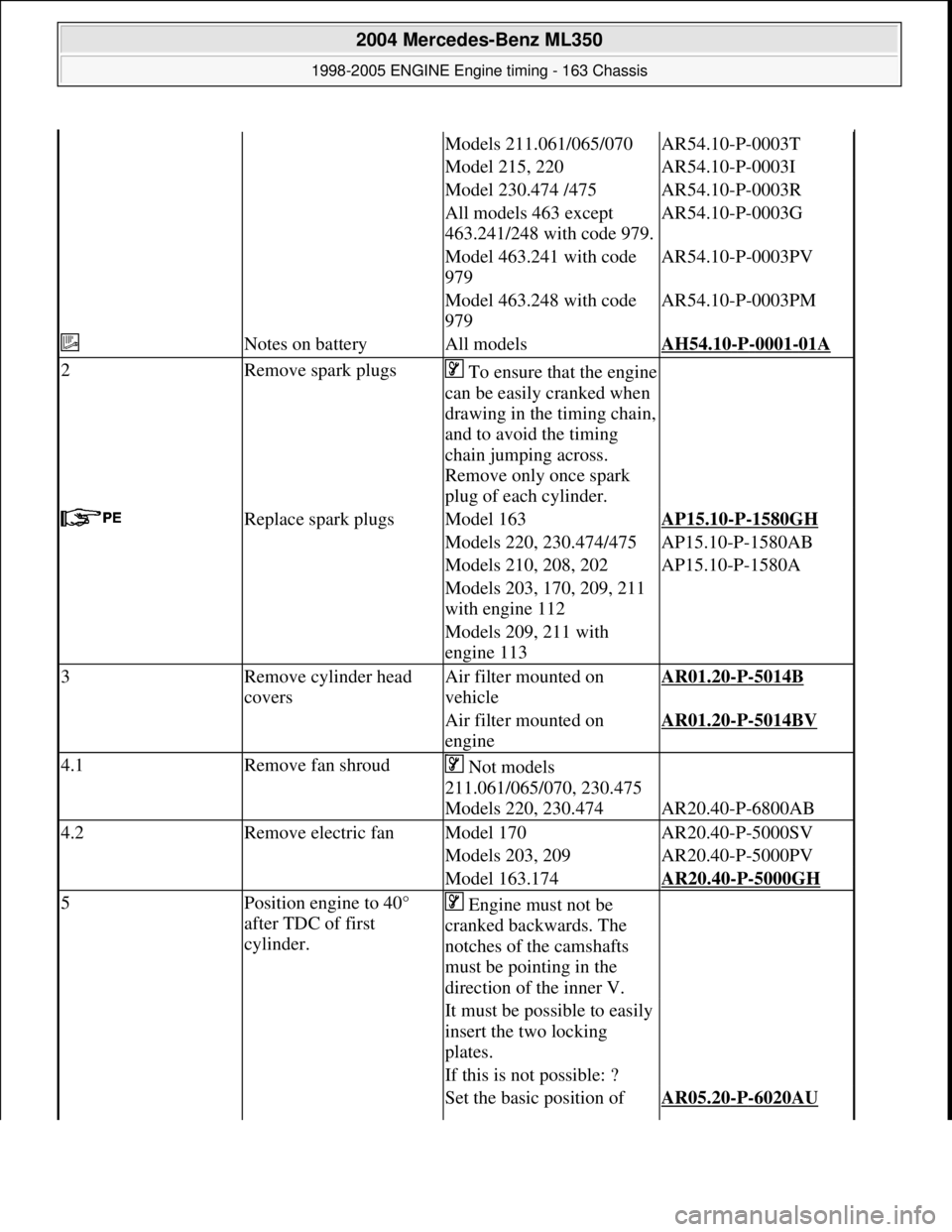
Models 211.061/065/070AR54.10-P-0003T
Model 215, 220AR54.10-P-0003I
Model 230.474 /475AR54.10-P-0003R
All models 463 except
463.241/248 with code 979.AR54.10-P-0003G
Model 463.241 with code
979AR54.10-P-0003PV
Model 463.248 with code
979AR54.10-P-0003PM
Notes on batteryAll modelsAH54.10-P-0001-01A
2Remove spark plugsTo ensure that the engine
can be easily cranked when
drawing in the timing chain,
and to avoid the timing
chain jumping across.
Remove only once spark
plug of each cylinder.
Replace spark plugsModel 163AP15.10-P-1580GH
Models 220, 230.474/475AP15.10-P-1580AB
Models 210, 208, 202AP15.10-P-1580A
Models 203, 170, 209, 211
with engine 112
Models 209, 211 with
engine 113
3Remove cylinder head
coversAir filter mounted on
vehicleAR01.20-P-5014B
Air filter mounted on
engineAR01.20-P-5014BV
4.1Remove fan shroud Not models
211.061/065/070, 230.475
Models 220, 230.474
AR20.40-P-6800AB
4.2Remove electric fanModel 170AR20.40-P-5000SV
Models 203, 209AR20.40-P-5000PV
Model 163.174AR20.40-P-5000GH
5Position engine to 40°
after TDC of first
cylinder. Engine must not be
cranked backwards. The
notches of the camshafts
must be pointing in the
direction of the inner V.
It must be possible to easily
insert the two locking
plates.
If this is not possible: ?
Set the basic position of AR05.20-P-6020AU
2004 Mercedes-Benz ML350
1998-2005 ENGINE Engine timing - 163 Chassis
me
Saturday, October 02, 2010 3:39:37 PMPage 29 © 2006 Mitchell Repair Information Company, LLC.
Page 2271 of 4133

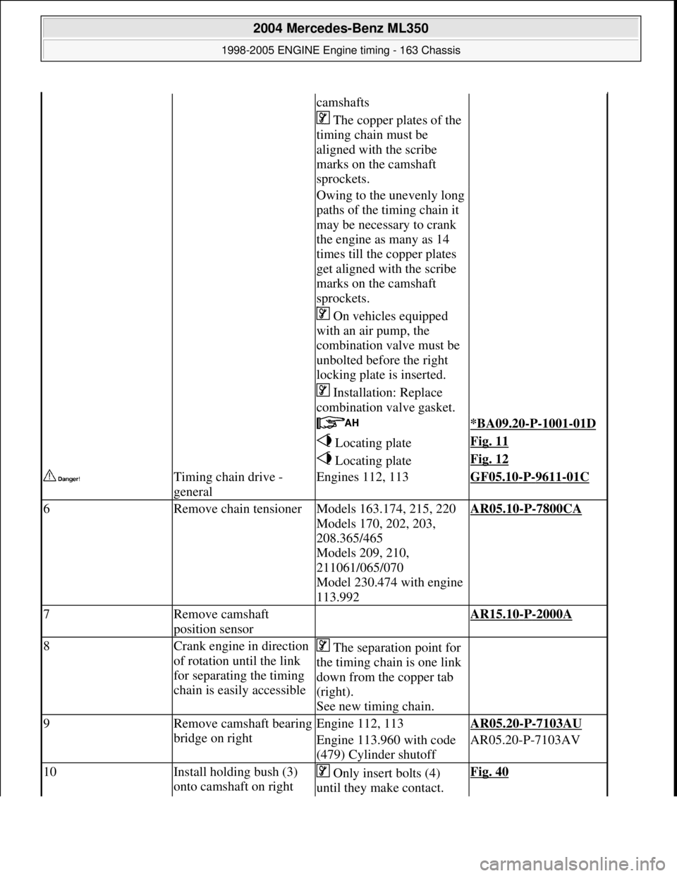
camshafts
The copper plates of the
timing chain must be
aligned with the scribe
marks on the camshaft
sprockets.
Owing to the unevenly long
paths of the timing chain it
may be necessary to crank
the engine as many as 14
times till the copper plates
get aligned with the scribe
marks on the camshaft
sprockets.
On vehicles equipped
with an air pump, the
combination valve must be
unbolted before the right
locking plate is inserted.
Installation: Replace
combination valve gasket.
*BA09.20-P-1001-01D
Locating plateFig. 11
Locating plateFig. 12
Timing chain drive -
generalEngines 112, 113GF05.10-P-9611-01C
6Remove chain tensionerModels 163.174, 215, 220
Models 170, 202, 203,
208.365/465
Models 209, 210,
211061/065/070
Model 230.474 with engine
113.992AR05.10-P-7800CA
7Remove camshaft
position sensor AR15.10-P-2000A
8Crank engine in direction
of rotation until the link
for separating the timing
chain is easily accessible The separation point for
the timing chain is one link
down from the copper tab
(right).
See new timing chain.
9Remove camsha ft bearing
bridge on rightEngine 112, 113AR05.20-P-7103AU
Engine 113.960 with code
(479) Cylinder shutoffAR05.20-P-7103AV
10Install holding bush (3)
onto camshaft on right Only insert bolts (4)
until they make contact. Fig. 40
2004 Mercedes-Benz ML350
1998-2005 ENGINE Engine timing - 163 Chassis
me
Saturday, October 02, 2010 3:39:37 PMPage 30 © 2006 Mitchell Repair Information Company, LLC.