1997 MERCEDES-BENZ ML320 service indicator
[x] Cancel search: service indicatorPage 1144 of 4133

340 IndexUseful features 164
Ashtrays and cigarette lighter 168
Cup holder 166
Electrical outlet 170
Garage door opener 180
Interior storage spaces 164
Programming or reprogramming the in-
tegrated remote control 182
Tele Aid* 171
Telephone* 170
Trip computer* 186
V
Vehicle
Locking 28
Locking in an emergency 262
Lowering 276
Proper use of 17
Service battery 278
Towing 283
Unlocking 28
Unlocking in an emergency 261
Vehicle and trailer weights and
ratings 207
Vehicle battery 278Vehicle care
Cup holder 238
Engine cleaning 236
Gear selector lever 238
Hard plastic trim items 238
Headlamps 236
Instrument cluster 238
Leather upholstery 239
Light alloy wheels 238
MB Tex upholstery 239
Ornamental moldings 236
Paintwork 235
Parktronic* system sensor 237
Plastic and rubber parts 239
Power washer 235
Seat belts 238
Steering wheel 238
Tail lamps 236
Tar stains 235
Turn signals 236
Upholstery 239
Vehicle washing 236
Window cleaning 237
Wiper blades 237Vehicle identification number (VIN) 292
Vehicle jack 258
Vehicle lighting
Checking 216
Vehicle tool kit 257
Vehicle with CD-changer* 258
Vehicle washing 236
VIN (Vehicle Identification Number) 292,
315
Voice control system* 315
W
Warning indicators
Parktronic* 155
Warning sounds
Drivers seat belts 64
Parking brake 48
Warranty coverage 291
Washer fluid see Windshield washer fluid
Washing the vehicle 234
Page 1150 of 4133

GF54.30-P-3010A
Function of acoustic warnings
24.10.96
MODEL
129, 140 as of 1.6.96,
163, 168, 170,
202 as of 1.8.96,
208 up to 31.7.99,
210 as of 1.6.96 up to 30.6.99
Display
Function
Turn signal indicator
ticking
Switching on the turn signal indicator is
indicated acoustically by the turn signal
indicator ticking. The driver's attention is
brought to a defect in the turn signal system
by the turn signal indicator ticking at a higher
frequency.
Turn signal indicator ticking is generated
electromagnetically. The frequency
corresponds to that of the turn signal indicator
lamp.
The signal comes from the combination relay
(turn signal indicator with trailer coupling, rear
window defroster), wiper motor, ATA (N10/2),
on model 210 from the multi-function control
module (N10-1) or from the driver-side signal-
acquisition and actuation module (SAM)
(N10/1), on model 163 from the All-Activity
Module (AAM, N10), on model 168 it is
generated by the integrated turn signal
indicator control in the instrument cluster (A1).
Parking brake reminderThe parking brake warning sounds when
terminal 15g is ON from a speed of approx. 5
km/h.
Piezoelectric loudspeaker (quartz), function
GF54.30-P-3017A
Gear warning, model 168
only with automatic
transmission or automatic
clutch
The acoustic gear warning is active, when
D
a gear is engaged
and
D
the brake is
not
depressed
and
D
the accelerator pedal is
not
pressed
and
D
the driver's door is opened.
These conditions are processed in the gear
recognition module (A61) or in the automatic
clutch control module (N15/4). The
information on the status of the driver's door
is available as a CAN message. It is
transmitted by the instrument cluster (A1).
Piezoelectric loudspeaker (quartz), function
GF54.30-P-3017A
Speed warning
The speed warning sounds when terminal
15g is ON from a speed of approx. 120 km/h.
(on national variants only)
Piezoelectric loudspeaker (quartz), function
GF54.30-P-3017A
Speed limit warning
The warning sounds if the set maximum
speed is exceeded by at least 6 km/h.
(on vehicles with variable cruise control only)
Piezoelectric loudspeaker (quartz), function
GF54.30-P-3017A
Seat belt reminder
On national variants only
Piezoelectric loudspeaker (quartz), function
GF54.30-P-3017A
Switched-on lights
reminder
The switched-on lights reminder sounds when
terminal 15g is OFF, terminal 58k is ON,
when the starter key is removed and the
driver's door is opened.
Piezoelectric loudspeaker (quartz), function
GF54.30-P-3017A
Key reminder
The key reminder when terminal 15g is OFF
and the driver's door is open when the starter
key is inserted
Piezoelectric loudspeaker (quartz), function
GF54.30-P-3017A
Soft top reminder, model
170 only
The soft top reminder sounds when terminal
15 is ON and soft top reminder input is on low
level.
Piezoelectric loudspeaker (quartz), function
GF54.30-P-3017A
Copyright DaimlerChrysler AG 05.06.2006 CD-Ausgabe G/10/04 . This WIS print-out will not be recorde
d by Modification services.
Page 1
Page 2034 of 4133

GF54.30-P-3007A
Charge indicator lamp, exterior lamp failure
24.10.96
MODEL
129, 140 as of 1.6.96,
163, 168, 170,
202 as of 1.8.96,
208 up to 31.7.99,
210 as of 1.6.96 up to 30.6.99
P54.30-0517-06
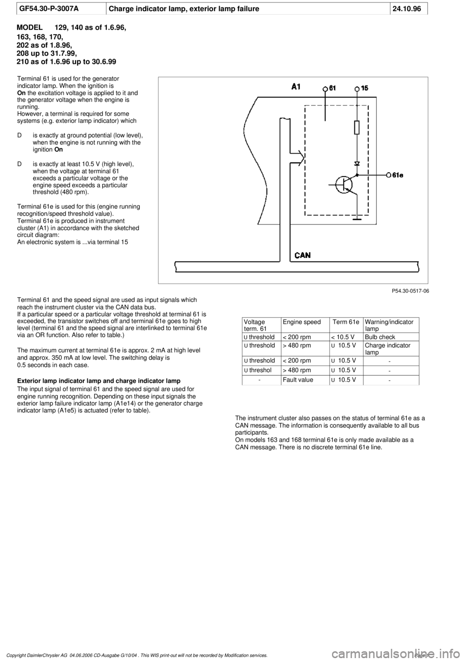
Terminal 61 is used for the generator
indicator lamp. When the ignition is
On
the excitation voltage is applied to it and
the generator voltage when the engine is
running.
However, a terminal is required for some
systems (e.g. exterior lamp indicator) which
D
is exactly at ground potential (low level),
when the engine is not running with the
ignition
On
D
is exactly at least 10.5 V (high level),
when the voltage at terminal 61
exceeds a particular voltage or the
engine speed exceeds a particular
threshold (480 rpm).
Terminal 61e is used for this (engine running
recognition/speed threshold value).
Terminal 61e is produced in instrument
cluster (A1) in accordance with the sketched
circuit diagram:
An electronic system is ...via terminal 15
Terminal 61 and the speed signal are used as input signals which
reach the instrument cluster via the CAN data bus.
If a particular speed or a particular voltage threshold at terminal 61 is
exceeded, the transistor switches off and terminal 61e goes to high
level (terminal 61 and the speed signal are interlinked to terminal 61e
via an OR function. Also refer to table.)
The maximum current at terminal 61e is approx. 2 mA at high level
and approx. 350 mA at low level. The switching delay is
0.5 seconds in each case.
Exterior lamp indicator lamp and charge indicator lamp
The input signal of terminal 61 and the speed signal are used for
engine running recognition. Depending on these input signals the
exterior lamp failure indicator lamp (A1e14) or the generator charge
indicator lamp (A1e5) is actuated (refer to table).
The instrument cluster also passes on the status of terminal 61e as a
CAN message. The information is consequently available to all bus
participants.
On models 163 and 168 terminal 61e is only made available as a
CAN message. There is no discrete terminal 61e line.
Voltage
term. 61
Engine speed
Term 61e
Warning/indicator
lamp
U
threshold
< 200 rpm
< 10.5 V
Bulb check
U
threshold
> 480 rpm
U
10.5 V
Charge indicator
lamp
U
threshold
< 200 rpm
U
10.5 V
-
U
threshol
> 480 rpm
U
10.5 V
-
-
Fault value
U
10.5 V
-
Copyright DaimlerChrysler AG 04.06.2006 CD-Ausgabe G/10/04 . This WIS print-out will not be recorde
d by Modification services.
Page 1
Page 2077 of 4133

GF54.30-P-4103GH
Coolant level switch, location/task/design/function
28.6.99
MODEL
163 as of 1.3.99
P54.30-2690-06
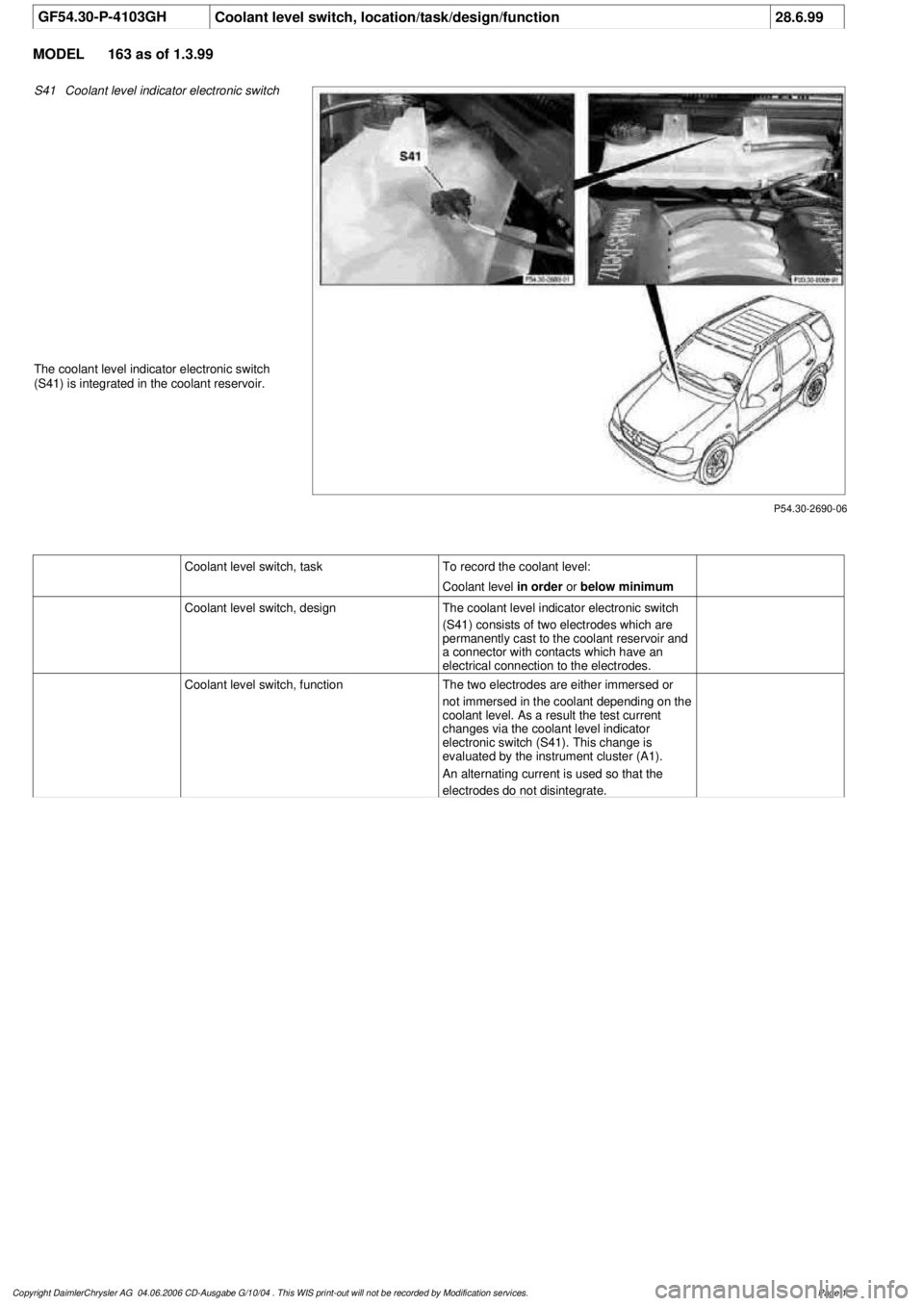
S41
Coolant level indicator electronic switch
The coolant level indicator electronic switch
(S41) is integrated in the coolant reservoir.
Coolant level switch, taskTo record the coolant level:
Coolant level
in order
or
below minimum
Coolant level switch, design
The coolant level indicator electronic switch
(S41) consists of two electrodes which are
permanently cast to the coolant reservoir and
a connector with contacts which have an
electrical connection to the electrodes.
Coolant level switch, function
The two electrodes are either immersed or
not immersed in the coolant depending on the
coolant level. As a result the test current
changes via the coolant level indicator
electronic switch (S41). This change is
evaluated by the instrument cluster (A1).
An alternating current is used so that the
electrodes do not disintegrate.
Copyright DaimlerChrysler AG 04.06.2006 CD-Ausgabe G/10/04 . This WIS print-out will not be recorde
d by Modification services.
Page 1
Page 2105 of 4133

GF54.30-P-2002A
Display instruments, location / task / function
24.10.96
MODEL
129, 140 as of 1.6.96,
163, 168, 170,
202 as of 1.8.96,
208 up to 31.7.99,
210 as of 1.6.96 up to 30.6.99
Display
Type of data transmission
D
Outside temperature indicator (A1p4)
D
Fuel level gauge (A1p2)
D
Engine oil pressure gauge (A1p3), only
model 129 and model 140
D
Low windshield washer fluid level
indicator lamp (A1e13), model 163 as of
01.09.01
Direct lines
GF54.30-P-3004A
D
Total mileage odometer (A1h4)
D
Electronic speedometer (A1p8)
D
Tachometer (A1p5)
D
Coolant temperature gauge (A1p1)
D
Active service system (ASSYST)
D
Gear indicator (A1p12), only model 168
CAN data lines
GF54.30-P-3005A
D
Electronic clock
Internal
GF54.30-P-3011A
Copyright DaimlerChrysler AG 04.06.2006 CD-Ausgabe G/10/04 . This WIS print-out will not be recorde
d by Modification services.
Page 1
Page 2107 of 4133

GF54.30-P-3028GH
Displaying coolant level, function
28.6.99
MODEL
163 as of 1.3.99
Function prerequisite
Engine: ON
Function
If the coolant level drops below the minimum mark the low ECL
indicator lamp (A1p11) is illuminated.
To record the coolant level the instrument cluster (A1) is connected
direct to the
coolant level indicator electronic switch (S41)
via two
cables. The
coolant level indicator electronic switch (S41)
consists of two electrodes.
D
If the
level is correct
both electrodes are immersed in the
coolant. The coolant serves as a dielectric between the
electrodes.
D
If the coolant level is below the minimum mark the electrodes of
the sensor are no longer immersed in the coolant. There is only
air between the electrodes as a dielectric. Evaluation
The instrument cluster (A1) sends test pulses to the sensor for
a period of one millisecond. These pulses are deformed
differently depending on the dielectric (air or coolant).
The instrument cluster (A1) evaluates the pulse shape and, if
the coolant level is below the minimum (electrodes are
completely in air), actuates the low ECL indicator lamp (A1p11)
after a delay of
approx. 60 seconds
.
The delay serves to prevent the indicator lamp flickering due to
the coolant moving from side to side on corners or off-road.
Diagnosis
Diagnosis is carried out, as described in the Diagnosis Manual, via
the simulation of the
coolant level indicator electronic switch (S41)
by a resistance.
Coolant level switch,
location/task/design/function
GF54.30-P-4103GH
Copyright DaimlerChrysler AG 04.06.2006 CD-Ausgabe G/10/04 . This WIS print-out will not be recorde
d by Modification services.
Page 1
Page 2842 of 4133

Fig. 318: Identifying Active Service System (ASSYST) Display
ACTIVE SERVICE SYSTEM (ASSYST) INFLUENCING PARAMETERS - GF00.20-P-0003-05A
The values of various influencing parameters are required by ASSYST for calculating the demand-based service
interval, and these are included in the calculation of the service interval as weighting factors . There are two
versions within ASSYST, the difference being in the oil level sensors fitted:
The familiar oil level indicator switch (S43) is fitted to engines (104, 111, 119, 120, 602.982, 604, 605,
606). In view of the fact that this is a switch, it is only possible to detect if the oil level drops below the
minimum level.
The oil sensor (oil level/temperature/quality, B40) is used on more recent engines (e.g. 112, 113, 166,
611, 668). This sensor consists of 2 capacitor systems with the engine oil as an insulator. If the water
content of the oil or the oil level changes, there is a change in the capacitance of the "capacitor".
The capacitance is thus a measure for the oil level.
In addition, the oil sensor (oil level/temperature/quality, B40) contains a temperature sensor which
detects the temperature of the engine oil.
All the signals are processed in the electronics integrated in the sensor to form a PWM (pulse width
modulated) signal, and passed to the engine control module (N3).
In addition to the weighting factors, which depend on reallife driving conditions, quality factors are also used
for calculating the demand-based service interval (remaining distance and remaining time).
Survey of ASSYST influencing parameters
Weighting factors (dependant on reallife driving conditions):
Load torque
Engine speed
Oil level
Engine oil temperature
Oil correction factor (is used as comparative value for determining oil level)
Coolant temperature
These data are supplied by the injection system control module (N3) to the service microprocessor over
the CAN.
The data relating to oil level, engine oil temperature and oil correction factor are supplied by the oil
sensor (oil level/temperature/quality, B40) through the injection system control module (N3), and are
therefore only available on engines fitted with this sensor.
Quality factors (these are factory-set to base values and can be changed with the HHT, if operating
conditions of the vehicle so necessitate; they influence the start distance):
2004 Mercedes-Benz ML350
1998-2005 GENINFO Overall vehicle - 163 Chassis
me
Saturday, October 02, 2010 3:47:47 PMPage 197 © 2006 Mitchell Repair Information Company, LLC.
Page 2843 of 4133

Engine version factor (gasoline/diesel)
National factor (The kilometer or mileage is coded in accordance with the national version.)
Distance travelled :
ASSYST is supplied with the 4 wheel speeds from the traction systems control module (N47) over the
CAN for calculating the distance travelled.
Time
ASSYST is supplied with the time information from the clock integrated in the instrument cluster.
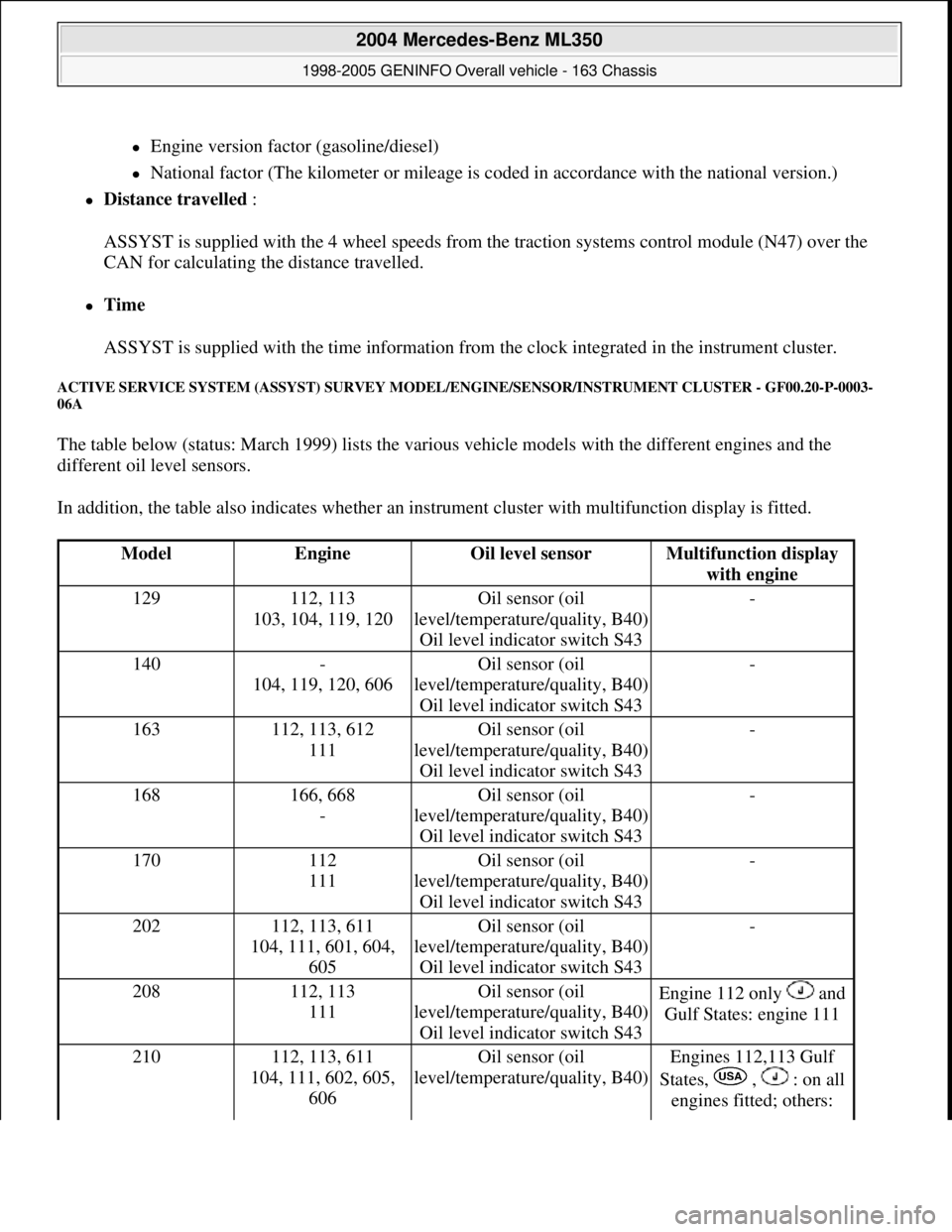
ACTIVE SERVICE SYSTEM (ASSYST) SURVEY MODEL/ENGINE/SENSOR/INSTRUMENT CLUSTER - GF00.20-P-0003-
06A
The table below (status: March 1999) lists the various vehicle models with the different engines and the
different oil level sensors.
In addition, the table also indicates whether an instrument cluster with multifunction display is fitted.
ModelEngineOil level sensorMultifunction display
with engine
129112, 113
103, 104, 119, 120Oil sensor (oil
level/temperature/quality, B40)
Oil level indicator switch S43-
140-
104, 119, 120, 606Oil sensor (oil
level/temperature/quality, B40)
Oil level indicator switch S43-
163112, 113, 612
111Oil sensor (oil
level/temperature/quality, B40)
Oil level indicator switch S43-
168166, 668
-Oil sensor (oil
level/temperature/quality, B40)
Oil level indicator switch S43-
170112
111Oil sensor (oil
level/temperature/quality, B40)
Oil level indicator switch S43-
202112, 113, 611
104, 111, 601, 604,
605Oil sensor (oil
level/temperature/quality, B40)
Oil level indicator switch S43-
208112, 113
111Oil sensor (oil
level/temperature/quality, B40)
Oil level indicator switch S43Engine 112 only and
Gulf States: engine 111
210112, 113, 611
104, 111, 602, 605,
606Oil sensor (oil
level/temperature/quality, B40)Engines 112,113 Gulf
States, , : on all
engines fitted; others:
2004 Mercedes-Benz ML350
1998-2005 GENINFO Overall vehicle - 163 Chassis
me
Saturday, October 02, 2010 3:47:47 PMPage 198 © 2006 Mitchell Repair Information Company, LLC.