1997 MERCEDES-BENZ ML320 service indicator
[x] Cancel search: service indicatorPage 624 of 4133
157
Tele Aid
Te ch n ica l
data
Instruments
and controls Operation
Driving Instrument
cluster display Practical hints Car care Index
Important!
If the indicator lamp continues to flash or the system
does not reset, contact the Response Center at
1-800-756-9018 (in the USA) or 1-888-923-8367 (in
Canada), or Mercedes-Benz Client Assistance at
1-800-FOR-MERCedes (1-800-367-6372) in the USA or
Customer Service at 1-800-387-0100 in Canada.
Notes:
The indicator lamp for the respective button flashes
until the call is concluded and this can only be
completed by a Response Center or Client Assistance
Center representative, except Roadside assistance and
Information calls, which can also be terminated by
using the End button on the MCS unit.
When a Tele Aid call has been initiated, the MCS system
audio is muted and the selected mode (radio, tape or
CD) pauses. The optional cellular phone (if installed)
switches off. If you must use this phone, the vehicle
must be parked. Disconnect the coiled cord and place
the call. The navigation system (if engaged) will
continue to run. A pop-up window will appear in the
MCS display to indicate that a Tele Aid call is in
progress. Remote door unlock
In the case you have your vehicle locked unintentionally
(e.g. key inside vehicle), and the reserve key is not
handy, contact the Mercedes-Benz Response Center at
1-800-756-9018 (in the USA) or 1-888-923-8367 (in
Canada). You will be asked to provide your password
which you provided when you completed the subscriber
agreement.
Then return to your vehicle and pull outside handle of
liftgate for a minimum of 20 seconds until the “SOS”
button is flashing.
As an alternative, you may unlock the vehicle via
Internet using the ID and password sent to you shortly
after the completion of your Acquaintance Call.
The Response Center will then unlock your vehicle with
the remote door unlocking feature.
Note:
The remote door unlock feature is available if the
relevant cellular phone network is available.
The SOS button will f lash and the message
“EMERGENCY CALL – CALL CONNECTED” will appear
in t he MCS display to indica te receipt of t he d oor unlock
command.
Page 626 of 4133
159
Tele Aid
Te ch n ica l
data
Instruments
and controls Operation
Driving Instrument
cluster display Practical hints Car care Index
Info Services
(optional, except Canada)
Info Services categories include news, sports, stocks,
weather and calendar reminders. Choices can be
selected via www.mbusa.com or by calling 1-800-FOR-
MERcedes.
To request Info Services press the TEL button and then
the SVC soft key on the MCS unit. Then select UPDT
soft key. “NEW INFO SERVICE REQUEST
TRANSMITTED” will appear in the MCS display and call
status messages will appear in the MCS display.
Once information is available, the message “NEW INFO
RECEIVED READ LATER WHEN STOPPED?” will appear.
Select “Yes”. With the vehicle stopped in a safe location
press TEL button, SVC soft key to read messages. Important!
Tele Aid utilizes the cellular network for
communication and the GPS (Global Positioning
System) satellites for vehicle location. If either of these
signals are unavailable, the Tele Aid system may not
function and if this occurs, assistance must be
summoned by other means.
Wa r n i n g !
The Tele Aid control unit is located under the front
passenger seat. If there is accumulation of water or
other liquid in this area, the Tele Aid control unit
could suffer an electrical short circuit making the
system inoperative. In this case the indicator lamp
in the “SOS” button will not illuminate during or
will remain illuminated after the system self-check.
Have the system checked at the nearest
Mercedes-Benz Light Truck Center as soon as
possible.
Page 669 of 4133
202
Driving systems
Te ch n ica l
data
Instruments
and controls Operation
Driving Instrument
cluster display Practical hints Car care Index
If the charging voltage falls below 10 volts, the
malfunction indicator lamp comes on and the ABS is
switched off. When the voltage is above this value again,
the malfunction indicator lamp should go out and the
ABS is operational.
If the ABS malfunction indicator lamp stays illuminated,
have the system checked at your authorized
Mercedes-Benz Light Truck Center as soon as possible. Notes:
To alert following vehicles to slippery road conditions
you discover, operate your hazard warning flashers as
appropriate.
Operating the vehicle on a single axle dynamometer
should only be done for briefly testing the brakes. To do
so, move selector lever to position “N”. The engine must
be shut off (key in steering lock position 0 or 1).
LOW RANGE – ABS
During off-road driving a special low range system for
the antilock brake system (ABS) is operational with
transmission in LOW RANGE mode, see page 211.
When applying the service brakes at speeds below
approximately 18 mph (30 km / h), the front wheels are
locked cyclically to shorten the braking distance (dig in
effect). This affects steering the vehicle.
Wa r n i n g !
ABS cannot prevent the natural laws of physics
from acting on the vehicle, nor can it increase
braking or steering efficiency beyond that afforded
by the condition of the vehicle brakes and tires or
the traction afforded. The ABS cannot prevent
accidents, including those resulting from excessive
speed in turns, following another vehicle too
closely, or aquaplaning. Only a safe, attentive, and
skillful driver can prevent accidents. The
capabilities of an ABS equipped vehicle must never
be exploited in a reckless or dangerous manner
which could jeopardize the user’s safety or the
safety of others.
Page 678 of 4133
211
Driving systems
Te ch n ica l
data
Instruments
and controls Operation
Driving Instrument
cluster display Practical hints Car care Index
Important!
During off-road driving a special low range system for
antilock brake system (ABS) and four-wheel electronic
traction system (4-ETS+) are operational with
transmission in the LOW RANGE mode.
In the low range mode the electronic stability program
(ESP) operates in a traction improving fashion
specifically adapted for off-road driving. At speeds
below 27 mph (45 km / h) the ESP assists in over- / understeering, thus improving vehicle tracking.
If one or more tires lose traction while driving downhill
(accelerator released), the 4-ETS+ engages and the
warning lamp v, located in the speedometer dial,
starts to f lash.
When applying the service brakes at speeds below
approximately 18 mph (30 km / h), the front wheels are
locked cyclically to shorten the braking distance (dig in
effect). This affects steering the vehicle. Notes:
Driving off or driving up to 3 mph (5 km / h) with the
service brakes applied lightly (to reduce drive wheel
spin), the 4-ETS+ remains engaged. Driving with the
service brakes applied lightly at vehicles speeds above
3 mph (5 km / h), the 4-ETS+ will not engage.
If the indicator lamp blinks fast, one or more switching
conditions were not observed, or the LOW RANGE mode
is defective.
In the case of a defective in the LOW RANGE mode the
transmission shifts in the usual manner. It is not
possible to switch on the LOW RANGE mode.
Have the transmission checked at your authorized
Mercedes-Benz Light Truck Center as soon as possible.
Page 691 of 4133
224
Malfunction and indicator lamps
Te ch n ica l
data
Instruments
and controls Operation Driving
Instrument
cluster display Practical hints Car care Index
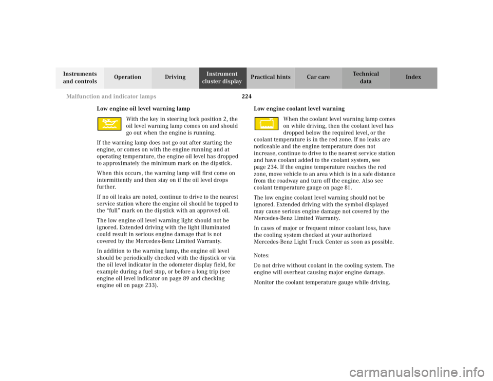
Low engine oil level warning lamp With the key in steering lock position 2, the
oil level warning lamp comes on and should
go out when the engine is running.
If the warning lamp does not go out after starting the
engine, or comes on with the engine running and at
operating temperature, the engine oil level has dropped
to approximately the minimum mark on the dipstick.
When this occurs, the warning lamp will first come on
intermittently and then stay on if the oil level drops
further.
If no oil leaks are noted, continue to drive to the nearest
service station where the engine oil should be topped to
the “full” mark on the dipstick with an approved oil.
The low engine oil level warning light should not be
ignored. Extended driving with the light illuminated
could result in serious engine damage that is not
covered by the Mercedes-Benz Limited Warranty.
In addition to the warning lamp, the engine oil level
should be periodically checked with the dipstick or via
the oil level indicator in the odometer display field, for
example during a fuel stop, or before a long trip (see
engine oil level indicator on page 89 and checking
engine oil on page 233). Low engine coolant level warning
When the coolant level warning lamp comes
on while driving, then the coolant level has
dropped below the required level, or the
coolant temperature is in the red zone. If no leaks are
noticeable and the engine temperature does not
increase, continue to drive to the nearest service station
and have coolant added to the coolant system, see
page 234. If the engine temperature reaches the red
zone, move vehicle to an area which is in a safe distance
from the roadway and turn off the engine. Also see
coolant temperature gauge on page 81.
The low engine coolant level warning should not be
ignored. Extended driving with the symbol displayed
may cause serious engine damage not covered by the
Mercedes-Benz Limited Warranty.
In cases of major or frequent minor coolant loss, have
the cooling system checked at your authorized
Mercedes-Benz Light Truck Center as soon as possible.
Notes:
Do not drive without coolant in the cooling system. The
engine will overheat causing major engine damage.
Monitor the coolant temperature gauge while driving.
Page 692 of 4133
225
Malfunction and indicator lamps
Te ch n ica l
data
Instruments
and controls Operation Driving
Instrument
cluster display Practical hints Car care Index
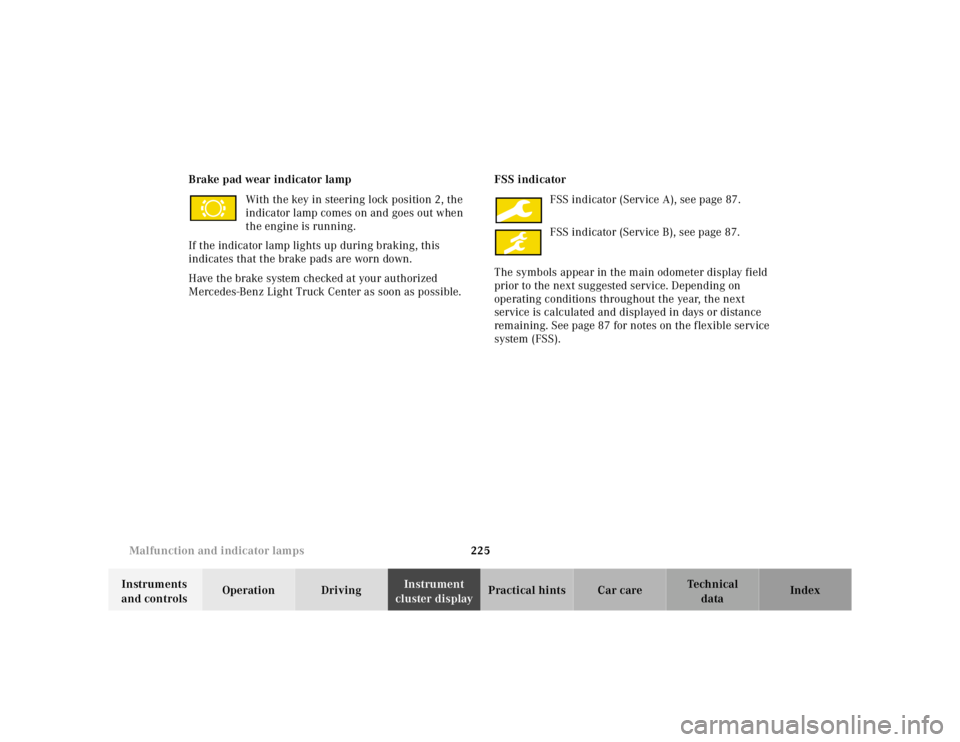
Brake pad wear indicator lamp
With the key in steering lock position 2, the
indicator lamp comes on and goes out when
the engine is running.
If the indicator lamp lights up during braking, this
indicates that the brake pads are worn down.
Have the brake system checked at your authorized
Mercedes-Benz Light Truck Center as soon as possible. FSS indicator
FSS indicator (Service A), see page 87.
FSS indicator (Service B), see page 87.
The symbols appear in the main odometer display field
prior to the next suggested service. Depending on
operating conditions throughout the year, the next
service is calculated and displayed in days or distance
remaining. See page 87 for notes on the flexible service
system (FSS).
Page 771 of 4133
304
Index
Te ch n ica l
data
Instruments
and controls Operation Driving
Instrument
cluster display Practical hints Car care
Index
FFirst aid kit .....................................................................228
Flexible service system (FSS) ........................................ 87
FSS indicator lamp ............................................ 79, 225
Floor plates Removable .................................................................. 129
Fog lamp switch ........................................................ 92, 93
Four ETS LOW RANGE – 4-ETS+ .............................................204
Malfunction indicator lamp ..................................... 221
Four wheel electronic traction system (4-ETS+) .......203 Malfunction indicator lamp ..................................... 221
Fuel Gasoline additives ....................................................296
Premium unleaded gasoline ................. 213, 293, 295
Fuel filler flap Manual release .......................................................... 274
Fuel requirements .........................................................295
Fuel reserve warning ....................................................220
Fuels, coolants, lubricants etc. - Capacities ..............292
Fuses, electrical .............................................................228
GGarage door opener .......................................................140
Gasoline
Additives .................................................................... 296
Fuel requirements ................................................... 295
Premium unleaded .................................................. 295
General notes on the central locking system .............. 26
Glass breakage sensor .................................................... 36
Glove box ......................................................................... 115HHazard warning flasher switch ..................................... 94
Head restraints Adjusting ......................................................................43
Front .............................................................................. 43
Front, removal ............................................................. 43
Rear .............................................................................124
Removal ............................................................... 43, 125
Headlamp aim, adjusting ............................................. 268
Headlamp assembly Halogen ....................................................................... 261
Xenon ......................................................................... 262
Page 775 of 4133
308
Index
Te ch n ica l
data
Instruments
and controls Operation Driving
Instrument
cluster display Practical hints Car care
Index
Remote control ................................................................. 24 Battery replacement .................................................270
Changing batteries ...................................................270
Operation ..................................................................... 26
Synchronizing remote control ................................ 271
Removable cargo floor plates ....................................... 129
Replacement keys ............................................................ 25
Replacing bulbs ..............................................................260
Replacing wiper blade insert .......................................275
Reporting safety defects ................................................. 16
Reserve key ................................................................ 24, 25
Roadside assistance ......................................................... 10
Roadside assistance call See Tele Aid ............................................................... 148
Roof rack ......................................................................... 276
SSafety guidelines for the seat belt, emergency tensioning retractor and airbag ................................ 63
Screwdriver .....................................................................237
Seat belt warning lamp .................................................223
Seat belts ........................................................................... 46 Fastening ...................................................................... 48
Seat belt nonusage warning system ........................ 47 Unfastening .................................................................. 50
Warning lamp ........................................................... 223
Seat belts and integrated restraint system .................. 46
Seat bench ....................................................................... 120
Seats, folding (Third row seats) ................................... 126
Seats, front ........................................................................37 Heated seats .................................................................44
Manual seats ................................................................39
Power seats .................................................................. 40
Service indicator
See Flexible service system (FSS) ............................ 87
Side marker lamp .......................................................... 264
Skyview Top ....................................................................109 Emergency operation .............................................. 273
Sliding/pop-up roof ........................................................107 Emergency operation .............................................. 272
Express opening ........................................................108
Synchronizing .......................................................... 272
Snow chains ....................................................................179
SOS-call See Tele Aid ...............................................................148
Space-saver tire
Air pump ................................................................... 239
Spare parts service ....................................................... 284
Spare wheel ................................................................... 242 Space-saver tire ........................................................ 243