1997 MERCEDES-BENZ ML320 radio code
[x] Cancel search: radio codePage 1609 of 4133
analog filters, digital filters contain the following significant advantages:
the filter parameters (sound settings) do not alter throughout the period, this thus means that all the
settings can be repeated exactly
low noise level
the component outlay is significantly reduced, as the filter parameters are set by the software and not by
varying component values (resistances, capacitances or inductance values), thus the number of possible
filter settings is increased
Sound optimizations
Each of the six amplifier channels is equipped with an individual compensation, which can, when requested,
rectify the vehicle's acoustics. In addition further sound optimization settings can be made and effects such as,
e.g. 'voice emphasizing' or 'stereoscopic sound' invoked.
Bass, treble, volume, balance, fader and the dynamic loudness function can be individually set.
Noise suppression
The output level of the six 6 output stages is constantly monitored and regulated such that distortion is kept to a
minimum.
Automatic Vehicle Noise Compensation (VNC))
With the aid of the sound amplifier microphone (B25/6) , which is connected directly to the sound amplifier
(A2/13) , the noise level in the vehicle is measured. The volume of the music output signal is constantly adapted
to this noise level. To this end the sound amplifier (A2/13) must be able to detect which of the measured
signals are noise emissions from the moving vehicle and which are audio signals. This is conducted by
comparing the output signal of the sound amplifier (A2/13) with the measured signal.
Put simply, the vehicle noise level is the difference between the two signals.
Diagnosis
The sound amplifier (A2/13) can set up the following messages which are relevant for the diagnosis:
Operating status
Undervoltage
Internal fault in the sound amplifier (A2/13)
The messages are sent over the digital databus ( D2B ) to the COMAND operating, display and control
module (A40/3) or the radio (A2) , and can be read out there over the ( K-wire ) diagnostics line.
SOUND AMPLIFIER, LOCATION/TASK/DESIGN/FUNCTION - GF82.62-P-3100GH
MODEL 163 with CODE (810) sound system
2001 Mercedes-Benz ML320
1998-2005 ACCESSORIES & BODY, CAB Electrical System - Body - 163 Chassis
me
Saturday, October 02, 2010 3:30:06 PMPage 114 © 2006 Mitchell Repair Information Company, LLC.
Page 1613 of 4133
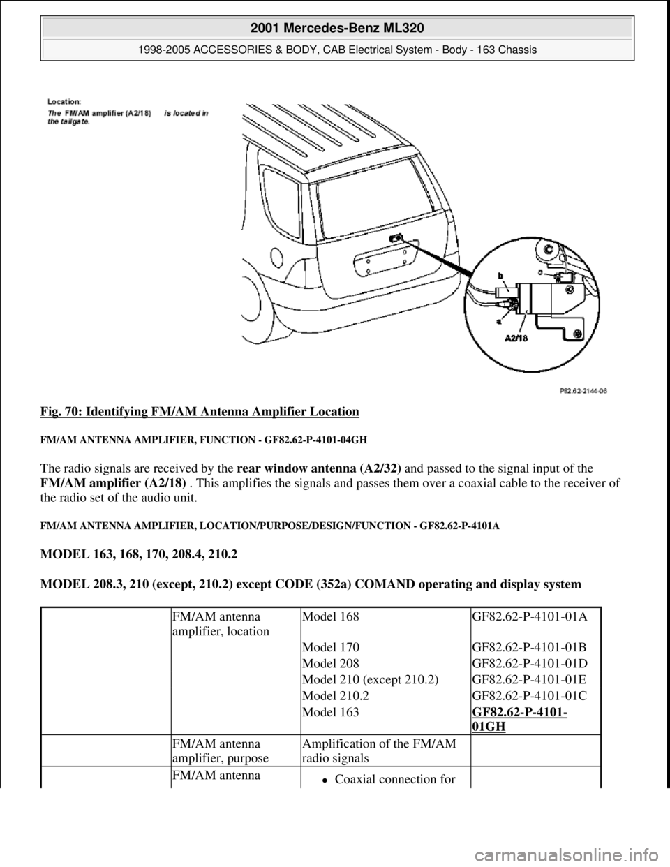
Fig. 70: Identifying FM/AM Antenna Amplifier Location
FM/AM ANTENNA AMPLIFIER, FUNCTION - GF82.62-P-4101-04GH
The radio signals are received by the rear window antenna (A2/32) and passed to the signal input of the
FM/AM amplifier (A2/18) . This amplifies the signals and passes them over a coaxial cable to the receiver of
the radio set of the audio unit.
FM/AM ANTENNA AMPLIFIER, LOCATION/PURPOSE/DESIGN/FUNCTION - GF82.62-P-4101A
MODEL 163, 168, 170, 208.4, 210.2
MODEL 208.3, 210 (except, 210.2) except CODE (352a) COMAND operating and display system
FM/AM antenna
amplifier, locationModel 168GF82.62-P-4101-01A
Model 170GF82.62-P-4101-01B
Model 208GF82.62-P-4101-01D
Model 210 (except 210.2)GF82.62-P-4101-01E
Model 210.2GF82.62-P-4101-01C
Model 163GF82.62-P-4101-
01GH
FM/AM antenna
amplifier, purposeAmplification of the FM/AM
radio signals
FM/AM antenna Coaxial connection for
2001 Mercedes-Benz ML320
1998-2005 ACCESSORIES & BODY, CAB Electrical System - Body - 163 Chassis
me
Saturday, October 02, 2010 3:30:06 PMPage 118 © 2006 Mitchell Repair Information Company, LLC.
Page 1617 of 4133
The laser-optical device scans the non-labeled side of the rotating CDwithout making contact and converts the
digital optical signals into electrical signals. Small interruptions in the data flow of the laser optics caused by
scratches or contamination on the audio CD are compensated by the D/A converter supplementing the missing
values .
The electrical signals are then decoded in the CD player with changer (in trunk) (A2/6) and transmitted via
the digital data bus ( D2B ) to the radio and navigation module (A2/56) via the audio signal processing or
when the sound amplifier (A2/13) (code 810) is installed to the loudspeakers.
Jumps and interruptions during playback
On bad roads or in the event of heavy vibrations , jumps and interruptions can occur during playback. In
such cases do not start CD mode until better road conditions are present.
In the event of wet weather conditions and strong deviations in the ambient temperatures moisture can collect in
the CD player housing (condensation formation). This could also lead to malfunctions in the playback. In such
cases provide for sufficient ventilation of the CD player and the trunk.
CD PLAYER WITH CHANGER, LOCATION/TASK/DESIGN/FUNCTION - GF82.64-P-3113B
MODELS 163, 208, 210, 215, 220 with CODE (819) 6-disc CD changer
MODELS 208, 210, 215, 220 with CODE (819a) CD changer with CODE (498) Japanese version
Shown on model 220 (as of 1.9.02)
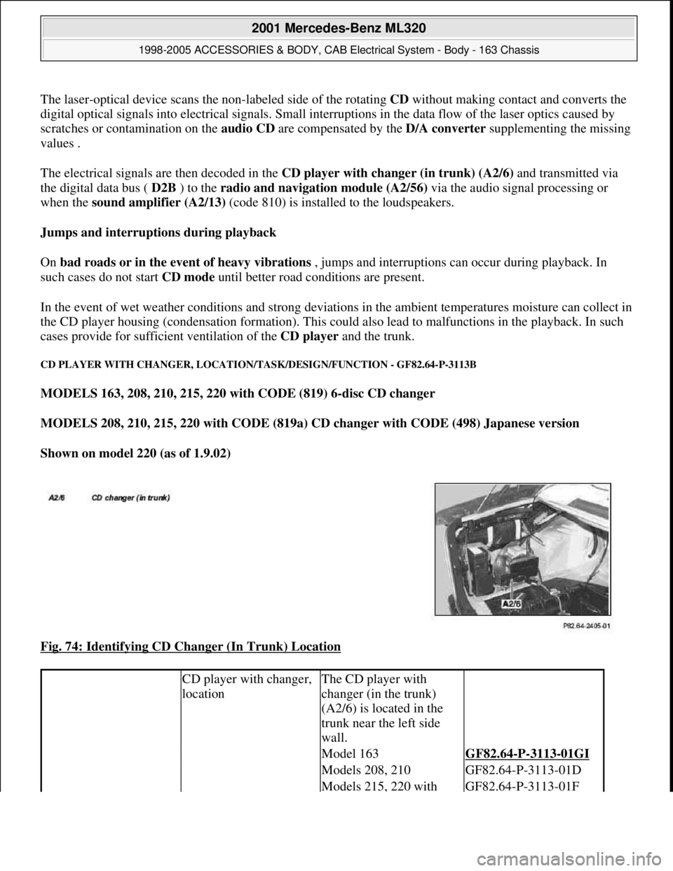
Fig. 74: Identifying CD Changer (In Trunk) Location
CD player with changer,
locationThe CD player with
changer (in the trunk)
(A2/6) is located in the
trunk near the left side
wall.
Model 163GF82.64-P-3113-01GI
Models 208, 210GF82.64-P-3113-01D
Models 215, 220 with GF82.64-P-3113-01F
2001 Mercedes-Benz ML320
1998-2005 ACCESSORIES & BODY, CAB Electrical System - Body - 163 Chassis
me
Saturday, October 02, 2010 3:30:06 PMPage 122 © 2006 Mitchell Repair Information Company, LLC.
Page 1618 of 4133
CD PLAYER WITH CHANGER, LOCATION/PURPOSE/DESIGN/FUNCTION - GF82.64-P-3113GI
MODEL 163 with CODE (522) Modular control system (MCS) radio USA with CODE (357) Navigation
system - additional unit with CODE (818b) Single CD player - additional unit with CODE (819) 6-disk
CD changer in trunk with CODE (491) U.S. version
code 498
Models 215, 220 without
code 498GF82.64-P-3113-01E
CD player with changer,
purposePlaying audio
compact discs (CD)
Changing CDs
contained in the
magazine
CD player with changer,
design6-slot CD changer
magazine
only: 12-slot
CD changer
magazine
Digital Data Bus
(D2B) interface
The factory planned
installation position for
the CD changer is vertical,
whereby other installation
positions are possible by
adaptation of the spring
locations.
CD player with changer,
functionModels 208, 210GF82.64-P-3113-02C
Model 215, 220GF82.64-P-3113-02B
2001 Mercedes-Benz ML320
1998-2005 ACCESSORIES & BODY, CAB Electrical System - Body - 163 Chassis
me
Saturday, October 02, 2010 3:30:06 PMPage 123 © 2006 Mitchell Repair Information Company, LLC.
Page 1622 of 4133
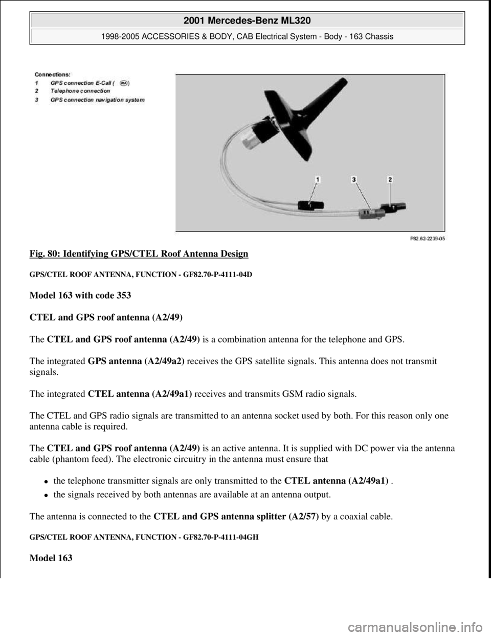
Fig. 80: Identifying GPS/CTEL Roof Antenna Design
GPS/CTEL ROOF ANTENNA, FUNCTION - GF82.70-P-4111-04D
Model 163 with code 353
CTEL and GPS roof antenna (A2/49)
The CTEL and GPS roof antenna (A2/49) is a combination antenna for the telephone and GPS.
The integrated GPS antenna (A2/49a2) receives the GPS satellite signals. This antenna does not transmit
signals.
The integrated CTEL antenna (A2/49a1) receives and transmits GSM radio signals.
The CTEL and GPS radio signals are transmitted to an antenna socket used by both. For this reason only one
antenna cable is required.
The CTEL and GPS roof antenna (A2/49) is an active antenna. It is supplied with DC power via the antenna
cable (phantom feed). The electronic circuitry in the antenna must ensure that
the telephone transmitter signals are only transmitted to the CTEL antenna (A2/49a1) .
the signals received by both antennas are available at an antenna output.
The antenna is connected to the CTEL and GPS antenna splitter (A2/57) by a coaxial cable.
GPS/CTEL ROOF ANTENNA, FUNCTION - GF82.70-P-4111-04GH
Model 163
2001 Mercedes-Benz ML320
1998-2005 ACCESSORIES & BODY, CAB Electrical System - Body - 163 Chassis
me
Saturday, October 02, 2010 3:30:06 PMPage 127 © 2006 Mitchell Repair Information Company, LLC.
Page 1623 of 4133
Function up to 31.8.01
The GPS/CTEL roof antenna (A2/49) is a combination antenna for telephone and GPS.
The CTEL and GPS roof antenna (A2/49) receives the GPS satellite signals. No GPS signals are transmitted
over this range of the antenna.
The CTEL and GPS roof antenna (A2/49) receives and transmits the GSM radio signals.
The radio signals for CTEL and GPS are transmitted to the CTEL and GPS antenna splitter (A2/57) via a
common antenna cable.
The CTEL and GPS roof antenna (A2/49) is an active antenna .
It is supplied with direct voltage via the antenna cable ( phantom feed ). The electronics in the antenna must
ensure that the
transmission signals of the cellular telephone are transmitted by the CTEL and GPS roof antenna
(A2/49)
the received signals of both antennas are made available to an antenna output.
The antenna is linked via a coaxial cable to the CTEL and GPS antenna splitter (A2/57) .
Function as of 01.09.01
The CTEL and GPS roof antenna (A2/49) is a new version of the combination antenna for CTEL and GPS.
It has an integrated antenna splitter and an antenna amplifier, which eliminates the need for the CTEL and
GPS antenna splitter (A2/57) . splitter
The CTEL and GPS roof antenna (A2/49) has connections for
Cellular telephone,
GPS navigation system and
GPS E-Call ( )
GPS/TELEPHONE ROOF ANTENNA, LOCATION/TASK/DESIGN/FUNCTION - GF82.70-P-4111A
MODELS 140, 210 up to 31.5.98 with CODE (348) TELE AID emergency call system
MODELS 129, 202, 208.3, 210 as of 6/198, 220 with CODE (347) TELE AID emergency call system (D2B)
MODEL 140 as of 1.1.98, 168, 202, 208.3, 210.0 as of 1.1.98, 210.2 with CODE (351) Auto pilot system
(APS)
MODELS 163,168, 208.3, 210 with CODE (353) Audio 30 APS
2001 Mercedes-Benz ML320
1998-2005 ACCESSORIES & BODY, CAB Electrical System - Body - 163 Chassis
me
Saturday, October 02, 2010 3:30:06 PMPage 128 © 2006 Mitchell Repair Information Company, LLC.
Page 1624 of 4133
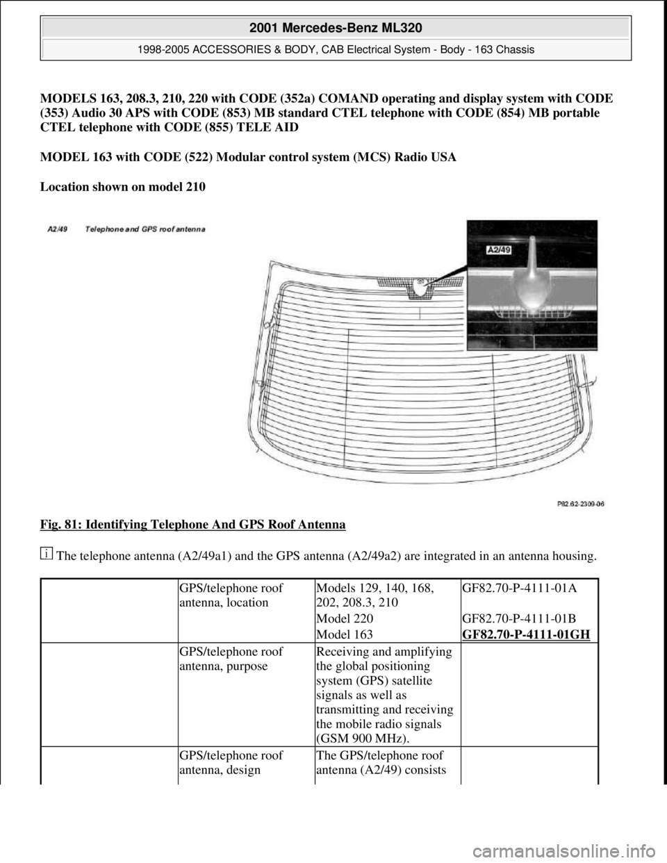
MODELS 163, 208.3, 210, 220 with CODE (352a) COMAND operating and display system with CODE
(353) Audio 30 APS with CODE (853) MB standard CTEL telephone with CODE (854) MB portable
CTEL telephone with CODE (855) TELE AID
MODEL 163 with CODE (522) Modular control system (MCS) Radio USA
Location shown on model 210
Fig. 81: Identifying Telephone And GPS Roof Antenna
The telephone antenna (A2/49a1) and the GPS antenna (A2/49a2) are integrated in an antenna housing.
GPS/telephone roof
antenna, locationModels 129, 140, 168,
202, 208.3, 210GF82.70-P-4111-01A
Model 220GF82.70-P-4111-01B
Model 163GF82.70-P-4111-01GH
GPS/telephone roof
antenna, purposeReceiving and amplifying
the global positioning
system (GPS) satellite
signals as well as
transmitting and receiving
the mobile radio signals
(GSM 900 MHz).
GPS/telephone roof
antenna, designThe GPS/telephone roof
antenna (A2/49) consists
2001 Mercedes-Benz ML320
1998-2005 ACCESSORIES & BODY, CAB Electrical System - Body - 163 Chassis
me
Saturday, October 02, 2010 3:30:06 PMPage 129 © 2006 Mitchell Repair Information Company, LLC.
Page 1625 of 4133
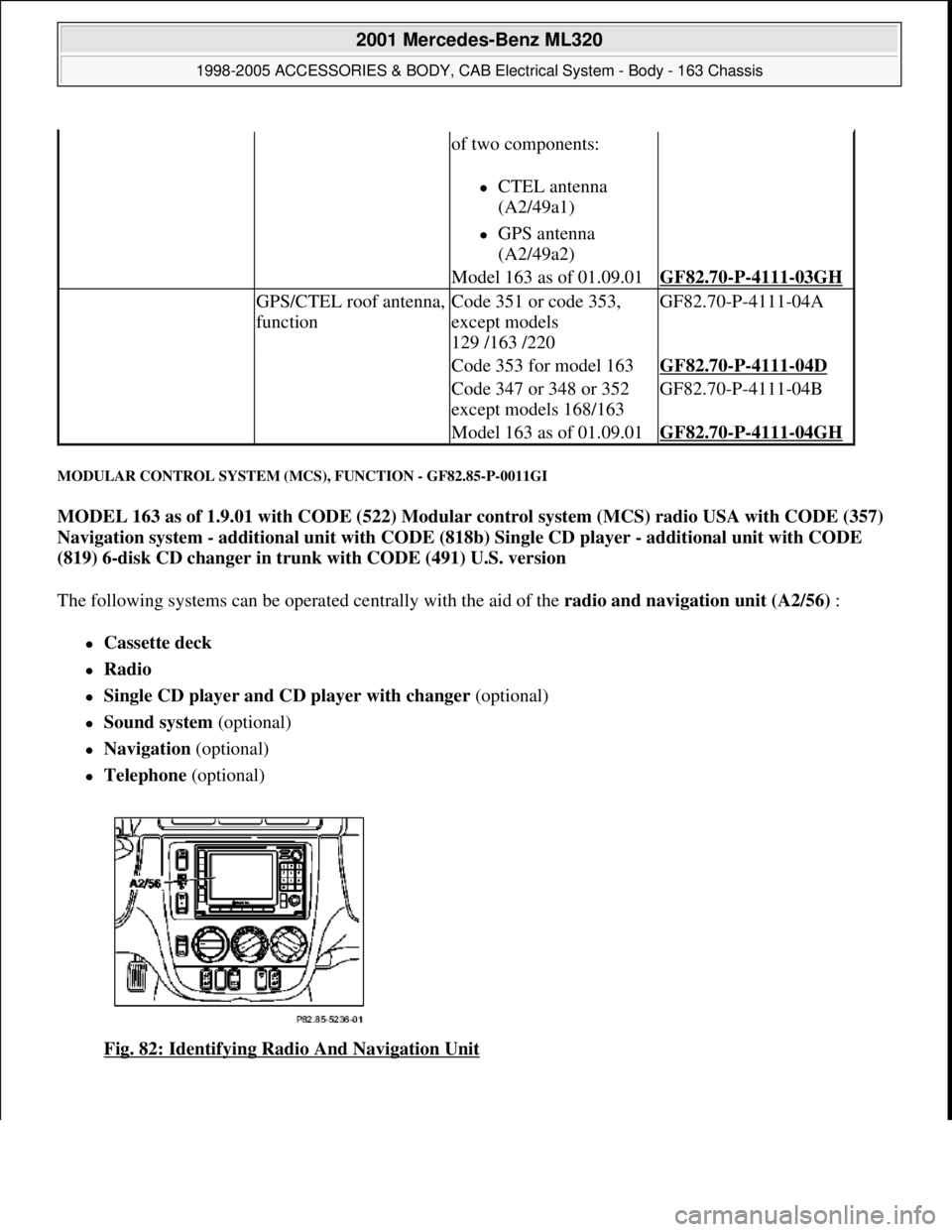
MODULAR CONTROL SYSTEM (MCS), FUNCTION - GF82.85-P-0011GI
MODEL 163 as of 1.9.01 with CODE (522) Modular control system (MCS) radio USA with CODE (357)
Navigation system - additional unit with CODE (818b) Single CD player - additional unit with CODE
(819) 6-disk CD changer in trunk with CODE (491) U.S. version
The following systems can be operated centrally with the aid of the radio and navigation unit (A2/56) :
Cassette deck
Radio
Single CD player and CD player with changer (optional)
Sound system (optional)
Navigation (optional)
Telephone (optional)
Fig. 82: Identifying Radio And Navigation Unit
of two components:
CTEL antenna
(A2/49a1)
GPS antenna
(A2/49a2)
Model 163 as of 01.09.01GF82.70-P-4111-03GH
GPS/CTEL roof antenna,
functionCode 351 or code 353,
except models
129 /163 /220GF82.70-P-4111-04A
Code 353 for model 163GF82.70-P-4111-04D
Code 347 or 348 or 352
except models 168/163GF82.70-P-4111-04B
Model 163 as of 01.09.01GF82.70-P-4111-04GH
2001 Mercedes-Benz ML320
1998-2005 ACCESSORIES & BODY, CAB Electrical System - Body - 163 Chassis
me
Saturday, October 02, 2010 3:30:06 PMPage 130 © 2006 Mitchell Repair Information Company, LLC.