Page 1821 of 4133
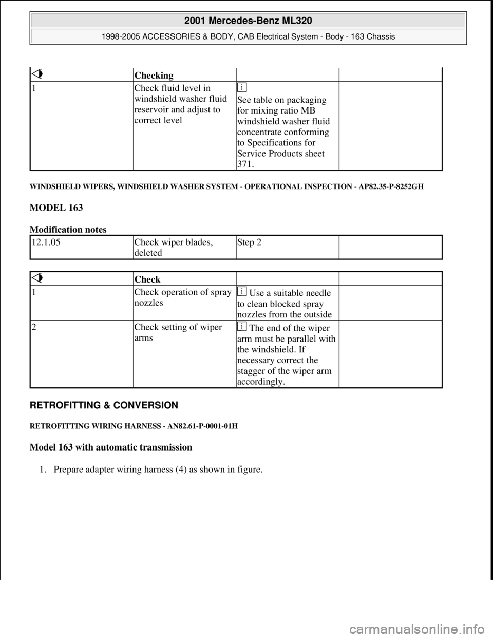
WINDSHIELD WIPERS, WINDSHIELD WASHER SYSTEM - OPERATIONAL INSPECTION - AP82.35-P-8252GH
MODEL 163
Modification notes
RETROFITTING & CONVERSION
RETROFITTING WIRING HARNESS - AN82.61-P-0001-01H
Model 163 with automatic transmission
1. Prepare adapter wirin
g harness (4) as shown in figure.
Checking
1Check fluid level in
windshield washer fluid
reservoir and adjust to
correct level
See table on packaging
for mixing ratio MB
windshield washer fluid
concentrate conforming
to Specifications for
Service Products sheet
371.
12.1.05Check wiper blades,
deletedStep 2
Check
1Check operation of spray
nozzles Use a suitable needle
to clean blocked spray
nozzles from the outside
2Check setting of wiper
arms The end of the wiper
arm must be parallel with
the windshield. If
necessary correct the
stagger of the wiper arm
accordingly.
2001 Mercedes-Benz ML320
1998-2005 ACCESSORIES & BODY, CAB Electrical System - Body - 163 Chassis
me
Saturday, October 02, 2010 3:30:10 PMPage 326 © 2006 Mitchell Repair Information Company, LLC.
Page 1959 of 4133
REMOVAL & INSTALLATION
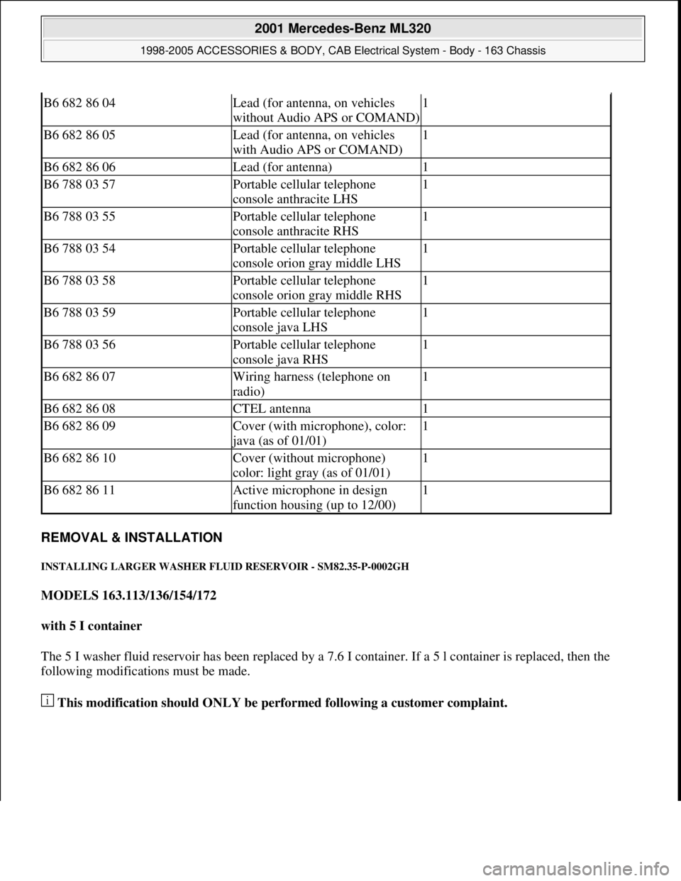
INSTALLING LARGER WASHER FLUID RESERVOIR - SM82.35-P-0002GH
MODELS 163.113/136/154/172
with 5 I container
The 5 I washer fluid reservoir has been replaced by a 7.6 I container. If a 5 l container is replaced, then the
following modifications must be made.
This modification should ONLY be performed following a customer complaint.
B6 682 86 04Lead (for antenna, on vehicles
without Audio APS or COMAND)1
B6 682 86 05Lead (for antenna, on vehicles
with Audio APS or COMAND)1
B6 682 86 06Lead (for antenna)1
B6 788 03 57Portable cellular telephone
console anthracite LHS1
B6 788 03 55Portable cellular telephone
console anthracite RHS1
B6 788 03 54Portable cellular telephone
console orion gray middle LHS1
B6 788 03 58Portable cellular telephone
console orion gray middle RHS1
B6 788 03 59Portable cellular telephone
console java LHS1
B6 788 03 56Portable cellular telephone
console java RHS1
B6 682 86 07Wiring harness (telephone on
radio)1
B6 682 86 08CTEL antenna1
B6 682 86 09Cover (with microphone), color:
java (as of 01/01)
1
B6 682 86 10Cover (without microphone)
color: light gray (as of 01/01)1
B6 682 86 11Active microphone in design
function housing (up to 12/00)1
2001 Mercedes-Benz ML320
1998-2005 ACCESSORIES & BODY, CAB Electrical System - Body - 163 Chassis
me
Saturday, October 02, 2010 3:30:14 PMPage 464 © 2006 Mitchell Repair Information Company, LLC.
Page 1960 of 4133
Fig. 410: Identifying Larger Was her Fluid Reservoir Components
Fig. 411: Larger Washer Fluid Reservoir Component Locations
Operation no. of operation texts or standard texts and flat rates
CategoryOp. no.Operation textTimeAcc. no.Code
P023591INSTALLING 023WU/1.9hrs.86 011 04-
2001 Mercedes-Benz ML320
1998-2005 ACCESSORIES & BODY, CAB Electr ical System - Body - 163 Chassis
me
Saturday, October 02, 2010 3:30:14 PMPage 465 © 2006 Mitchell Repair Information Company, LLC.
Page 1961 of 4133
LARGER
CONTAINER FOR
WINDSHIELD
WASHER SYSTEM
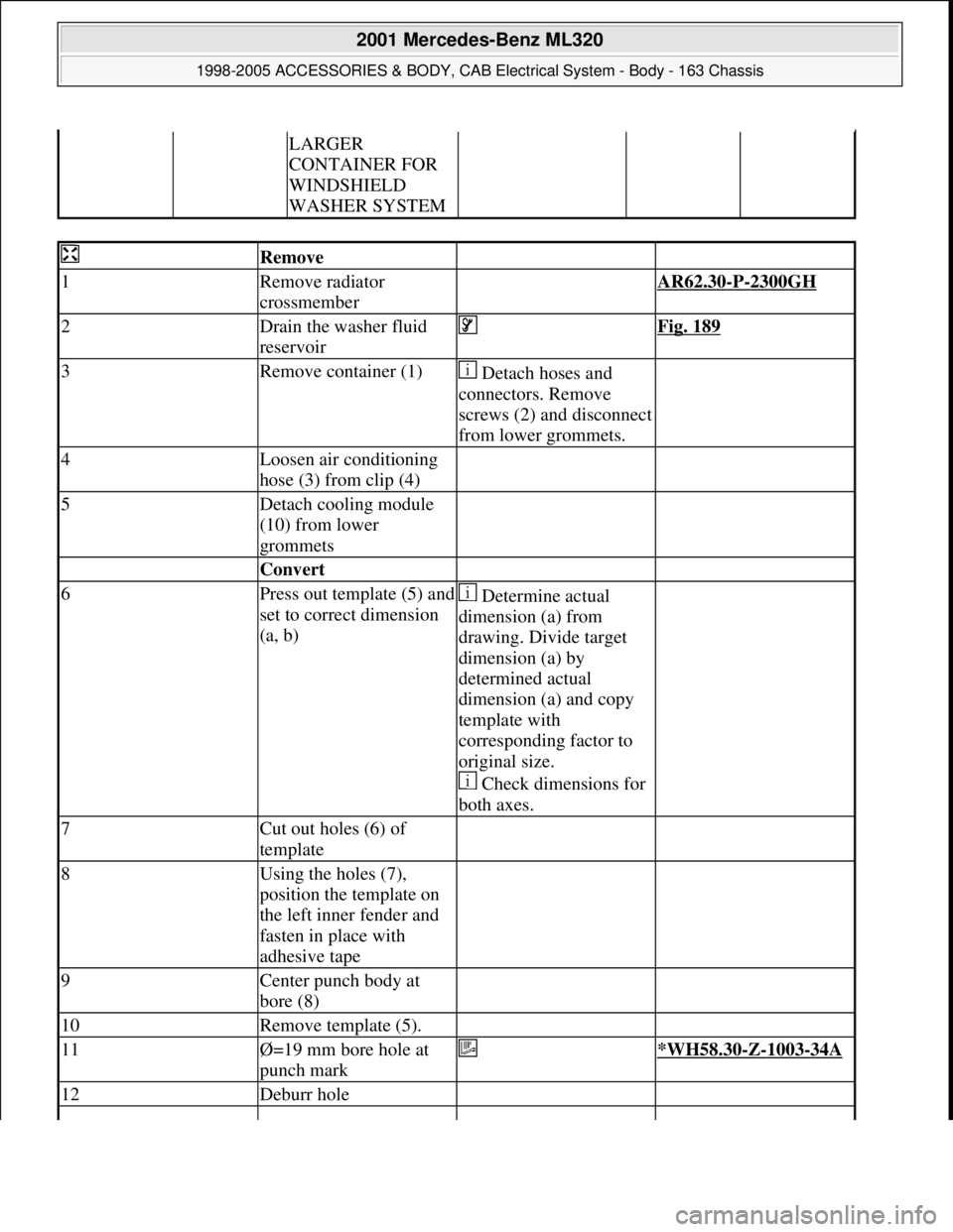
Remove
1Remove radiator
crossmember AR62.30-P-2300GH
2Drain the washer fluid
reservoir Fig. 189
3Remove container (1) Detach hoses and
connectors. Remove
screws (2) and disconnect
from lower grommets.
4Loosen air conditioning
hose (3) from clip (4)
5Detach cooling module
(10) from lower
grommets
Convert
6Press out template (5) and
set to correct dimension
(a, b) Determine actual
dimension (a) from
drawing. Divide target
dimension (a) by
determined actual
dimension (a) and copy
template with
corresponding factor to
original size.
Check dimensions for
both axes.
7Cut out holes (6) of
template
8Using the holes (7),
position the template on
the left inner fender and
fasten in place with
adhesive tape
9Center punch body at
bore (8)
10Remove template (5).
11Ø=19 mm bore hole at
punch mark *WH58.30-Z-1003-34A
12Deburr hole
2001 Mercedes-Benz ML320
1998-2005 ACCESSORIES & BODY, CAB Electrical System - Body - 163 Chassis
me
Saturday, October 02, 2010 3:30:14 PMPage 466 © 2006 Mitchell Repair Information Company, LLC.
Page 1962 of 4133
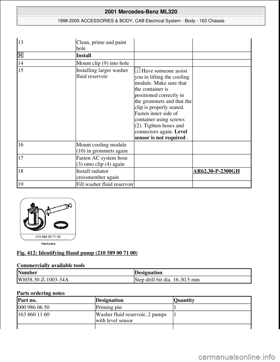
Fig. 412: Identifying Hand pump (210 589 00 71 00)
Commercially available tools
Parts ordering notes
13Clean, prime and paint
hole
Install
14Mount clip (9) into hole
15Installing larger washer
fluid reservoir Have someone assist
you in lifting the cooling
module. Make sure that
the container is
positioned correctly in
the grommets and that the
clip is properly seated.
Fasten inner side of
container using screws
(2). Tighten hoses and
connectors again. Level
sensor is not required .
16Mount cooling module
(10) in grommets again
17Fasten AC system hose
(3) onto clip (4) again
18Install radiator
crossmember again AR62.30-P-2300GH
19Fill washer fluid reservoir
NumberDesignation
WH58.30-Z-1003-34AStep drill bit dia. 16-30.5 mm
Part no.DesignationQuantity
000 986 06 50Priming pin1
163 860 11 60Washer fluid reservoir, 2 pumps
with level sensor1
2001 Mercedes-Benz ML320
1998-2005 ACCESSORIES & BODY, CAB Electrical System - Body - 163 Chassis
me
Saturday, October 02, 2010 3:30:14 PMPage 467 © 2006 Mitchell Repair Information Company, LLC.
Page 2105 of 4133
GF54.30-P-2002A
Display instruments, location / task / function
24.10.96
MODEL
129, 140 as of 1.6.96,
163, 168, 170,
202 as of 1.8.96,
208 up to 31.7.99,
210 as of 1.6.96 up to 30.6.99
Display
Type of data transmission
D
Outside temperature indicator (A1p4)
D
Fuel level gauge (A1p2)
D
Engine oil pressure gauge (A1p3), only
model 129 and model 140
D
Low windshield washer fluid level
indicator lamp (A1e13), model 163 as of
01.09.01
Direct lines
GF54.30-P-3004A
D
Total mileage odometer (A1h4)
D
Electronic speedometer (A1p8)
D
Tachometer (A1p5)
D
Coolant temperature gauge (A1p1)
D
Active service system (ASSYST)
D
Gear indicator (A1p12), only model 168
CAN data lines
GF54.30-P-3005A
D
Electronic clock
Internal
GF54.30-P-3011A
Copyright DaimlerChrysler AG 04.06.2006 CD-Ausgabe G/10/04 . This WIS print-out will not be recorde
d by Modification services.
Page 1
Page 2144 of 4133
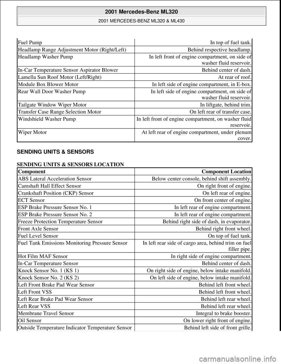
SENDING UNITS & SENSORS
SENDING UNITS & SENSORS LOCATION
Fuel PumpIn top of fuel tank.
Headlamp Range Adjustment Motor (Right/Left)Behind respective headlamp.
Headlamp Washer PumpIn left front of engine compartment, on side of
washer fluid reservoir.
In-Car Temperature Sensor Aspirator BlowerBehind center of dash.
Lamella Sun Roof Motor (Left/Right)At rear of roof.
Module Box Blower MotorIn left side of engine compartment, in E-box.
Rear Wall Door Washer PumpIn left side of engine compartment, on side of
washer fluid reservoir.
Tailgate Window Wiper MotorIn liftgate, behind trim.
Transfer Case Range Selection MotorOn left rear of transfer case.
Windshield Washer PumpIn left front of engine compartment, on washer fluid
reservoir.
Wiper MotorAt left rear of engine compartment, under plenum
cover.
ComponentComponent Location
ABS Lateral Acceleration SensorBelow center console, behind shift assembly.
Camshaft Hall Effect SensorOn right front of engine.
Crankshaft Position (CKP) SensorOn left rear of engine.
ECT SensorOn front center of engine.
ESP Brake Pressure Sensor No. 1In left rear of engine compartment.
ESP Brake Pressure Sensor No. 2In left rear of engine compartment.
Freeze Protection Temperature SensorBehind right side of dash, in evaporator.
Front Axle SensorBehind right front wheel.
Fuel Level SensorOn top of fuel tank.
Fuel Tank Emissions Monitoring Pressure SensorIn left rear side of cargo area, behind trim on fuel
filler pipe.
Hot Film MAF SensorIn right side of engine compartment.
In-Car Temperature SensorBehind center of dash.
Knock Sensor No. 1 (KS 1)On right side of engine, below intake manifold.
Knock Sensor No. 2 (KS 2)On left side of engine, below intake manifold.
Left Front Brake Pad Wear SensorBehind left front wheel.
Left Front VSSBehind left front wheel.
Left Rear Brake Pad Wear SensorBehind left rear wheel.
Left Rear VSSBehind left rear wheel.
Membrane Travel SensorIntegral to brake booster.
Oil SensorOn lower right front of engine.
Outside Temperature Indicator Temperature SensorBehind left side of front grille.
2001 Mercedes-Benz ML320
2001 MERCEDES-BENZ ML320 & ML430
me
Saturday, October 02, 2010 3:21:17 PMPage 4 © 2006 Mitchell Repair Information Company, LLC.
Page 3428 of 4133
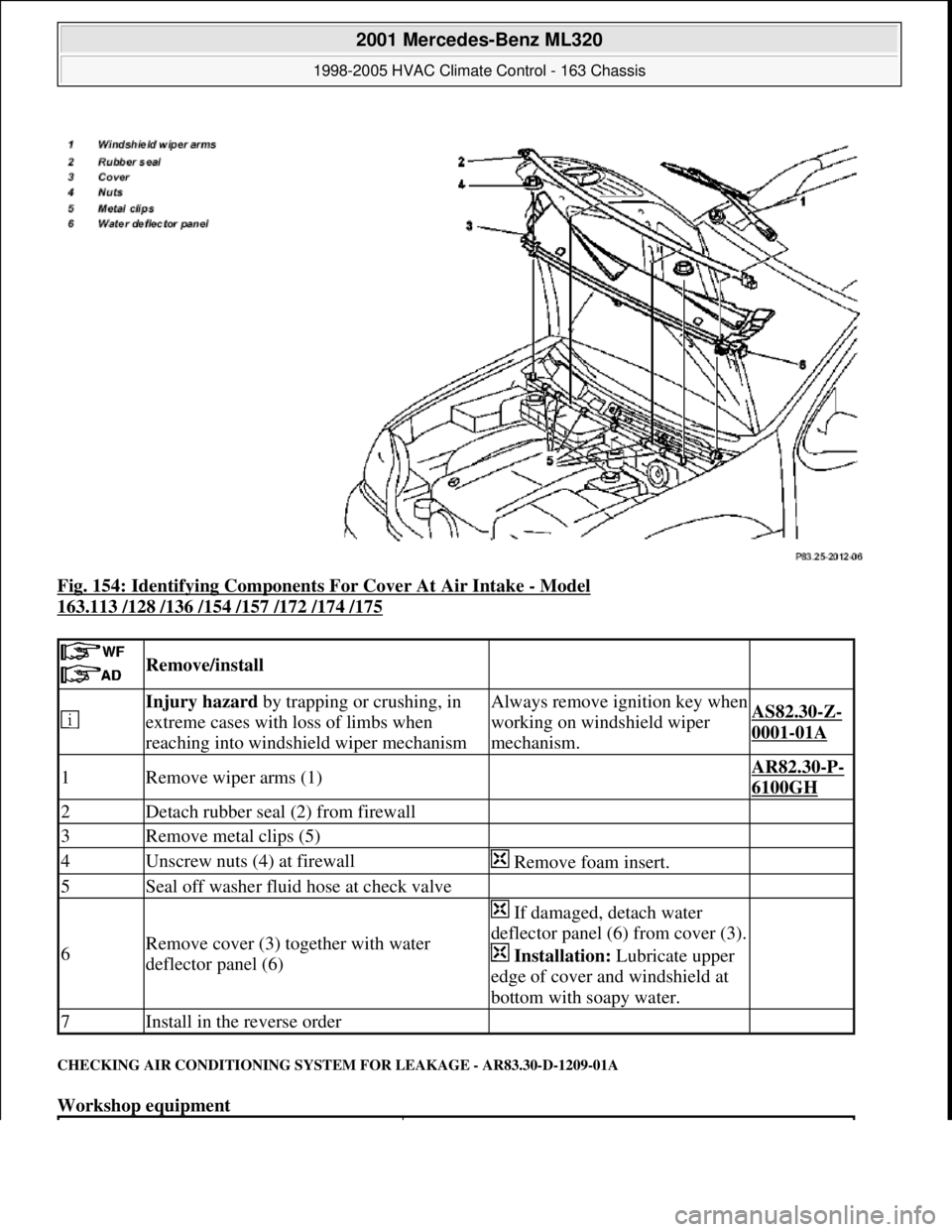
Fig. 154: Identifying Components For Cover At Air Intake - Model
163.113 /128 /136 /154 /157 /172 /174 /175
CHECKING AIR CONDITIONING SYSTEM FOR LEAKAGE - AR83.30-D-1209-01A
Workshop equipment
Remove/install
Injury hazard by trapping or crushing, in
extreme cases with loss of limbs when
reaching into windshield wiper mechanismAlways remove ignition key when
working on windshield wiper
mechanism.AS82.30-Z-
0001-01A
1Remove wiper arms (1) AR82.30-P-
6100GH
2Detach rubber seal (2) from firewall
3Remove metal clips (5)
4Unscrew nuts (4) at firewall Remove foam insert.
5Seal off washer fluid hose at check valve
6Remove cover (3) together with water
deflector panel (6)
If damaged, detach water
deflector panel (6) from cover (3).
Installation: Lubricate upper
edge of cover and windshield at
bottom with soapy water.
7Install in the reverse order
2001 Mercedes-Benz ML320
1998-2005 HVAC Climate Control - 163 Chassis
me
Saturday, October 02, 2010 3:23:18 PMPage 184 © 2006 Mitchell Repair Information Company, LLC.