1997 MERCEDES-BENZ ML320 engine
[x] Cancel search: enginePage 2097 of 4133

29
Slacken cylinder head bolts (21) in stages,
unscrew
Loosen cylinder head bolts according to
loosening schematic only after engine has
cooled down to prevent cylinder head from
distorting.
AR01.30-P-5800-09B
Installation:
Observe tightening pattern
and tightening instructions of cylinder head
bolts.
Oil thread and head contact surface of
cylinder head bolts.
AR01.30-P-5800-07B
Screwdriver insert
*000589031000
Screwdriver insert
*000589041000
*BA01.30-P-1001-01D
30
Remove cylinder head
Installation:
On Engine 112/113 observe
porous points in the left and right cylinder
head. If porous points are present, sealant
must be applied to the cylinder head gasket.
Notes on application of sealant to cylinder
head gasket.
Engine 112, 113
AH01.30-P-1000-04VA
The sealant must be applied within
10 minutes.
Loctite 5900 sealant.
*BR00.45-Z-1015-01A
31
Inspect version of cylinder head gasket
Assignment of cylinder head gasket
Information for assigning the cylinder head
gaskets
Engine 112, 113
AH01.30-P-1000-06V
32
Check cylinder head bolts (21)
AR01.30-P-5800-03B
*BE01.30-P-1001-04B
33
Clean sealing surfaces, inspect for cracks,
shrink holes and flatness, clean threaded
holes.
Pay attention to dowel sleeves (26) for
locating the cylinder head.
Sealing surfaces of crankcase and
cylinder head are provided with an 0.8 mm
thick silicone layer during series production.
At the time of repair installation, silicone
sealant is applied to the sealing area only in
case of any shrink holes.
The sealant must be applied within
10 minutes.
Loctite 5900 sealant.
*BR00.45-Z-1015-01A
34
Install in the reverse order
Danger!
Risk of accident
caused by vehicle starting
off by itself when engine is running.
Risk of
injury
caused by contusions and burns when
working in engine during starting procedure
Secure vehicle to prevent it from moving.
Wear closed and snug-fitting work clothes.
Do not grasp hot or rotating parts.
AS00.00-Z-0005-01A
35
Run engine and inspect for leaks
36
Inspect cooling system for leaks
Warm up engine to operating temperature
and then inspect cooling system or leaks.
AR20.00-P-1010HA
37
Read out and erase fault memory
Stored faults which can result from cables
being disconnected or from simulation during
removal and installation or test work, have to
be processed and erased in the fault
memories after completing the work:
#
Diagnosis Manual Volume 2 Index 0:
Connecting and using test equipment.
Cylinder head/cylinder head bolts
Number
Designation
Engine
112.910/911/912/
913/914/915/
916/917/920/
921/922/923/
940/941/942/
943/944/945/
946/947/949/
951/953/954/
955/960/961/
970/972/973/975
Engine
113.940/941/
942/943/944/
945/946/948/
960/961/962/
963/965/966/
967/968/969/
980/981/982/
984/986/987/
988/990/991/
992/993
BE01.30-P-1001-04B
Cylinder head bolt
Thread diameter
M
1111
Length (L) when new
mm
141.5141.5
Length (L)
mm
T
144.5
T
144.5
Copyright DaimlerChrysler AG 20.05.2006 CD-Ausgabe G/10/04 . This WIS print-out will not be recorde
d by Modification services.
Page 5
Page 2098 of 4133

Fig., see
AR01.30-P-5800-03BAR01.30-P-5800-03B
Cylinder head
Number
Designation
Engine
112.910/911/912/
913/914/915/
916/917/920/
921/922/923/
940/941/942/
943/944/945/
946/947/949/
951/953/954/
955/960/961/
970/972/973/975
Engine
113.940/941/
942/943/944/
948/960/961/
962/963/965/
966/967/968/
969/980/981/
982/984/986/
992
BA01.30-P-1001-01D
Bolt of cylinder head to
crankcase
1st stageNm
1010
2nd stage
Nm
3030
3rd stage
(°
9090
4th stage
(°
9090
Crankcase, timing case cover, end cover
Number
Designation
Engine
112
except
112.951
Engine
113.940/941/
942/943/944/
945/946/948/
960/961/962/
963/965/966/
967/968/969/
980/981/982/
984/986/992
BA01.40-P-1002-01C
Bolt, cylinder head to timing case cover
Nm
2020
Camshaft
Number
Designation
Engine
112
except 112.951
Engine
113.940/941/
942/943/944/
948/961/962/
963/965/966/
967/968/969/
980/981/982/
984/986/992
BA05.20-P-1001-01B
Bolt of camshaft sprocket
M12 x 45
1st stageNm
5050
2nd stage
(°
9090
Fuel rail
Number
Designation
Engine
112 except
112.945/951/
960/961
BA07.52-P-1001-01A
Fuel feed line to fuel rail
Nm
38
Copyright DaimlerChrysler AG 20.05.2006 CD-Ausgabe G/10/04 . This WIS print-out will not be recorde
d by Modification services.
Page 6
Page 2099 of 4133

Fuel rail
Number
Designation
Engine
113.940/941/
942/943/944/
945/946/948/
960/961/962/
963/965/966/
967/968/969/
980/981/982/
984/986/988/
BA07.52-P-1001-01A
Fuel feed line to fuel distributor
Nm
38
Exhaust manifold
Number
Designation
Engine
112
except
112.951
Engine
113.940/941/
942/943/944/
945/946/948/
960/961/962/
963/965/966/
967/968/969/
980/981/982/
984/986/992/
993
BA14.10-P-1002-01B
Flange connection of exhaust manifold or front
exhaust pipes
Nm
2020
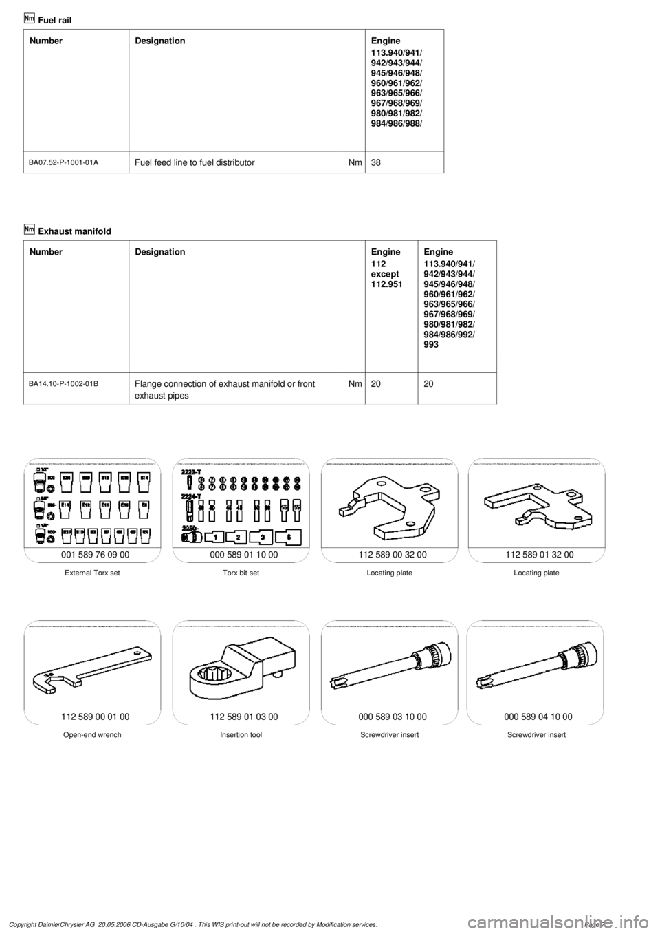
112 589 00 32 00 112 589 01 32 00
001 589 76 09 00 000 589 01 10 00
Locating plate
Torx bit set
External Torx set
Locating plate
112 589 01 03 00
Screwdriver insert
Insertion tool
Open-end wrench
Screwdriver insert
112 589 00 01 00000 589 03 10 00000 589 04 10 00
Copyright DaimlerChrysler AG 20.05.2006 CD-Ausgabe G/10/04 . This WIS print-out will not be recorde
d by Modification services.
Page 7
Page 2101 of 4133

AR01.20-P-5014-02B
Remove/install cylinder head cover trim
Crankcase ventilation, cylinder head cover
Number
Designation
Engine
612.961/
962/967
Engine
612.963
Engine
612.965/
966
Engine
612.990
BA01.20-P-1002-01A
Screw of trim panel of cylinder head cover
to cylinder head cover
NM
101010
8
BA01.20-P-1003-01A
Screw attaching cover panel to charge air
distribution pipe
NM
101010
-
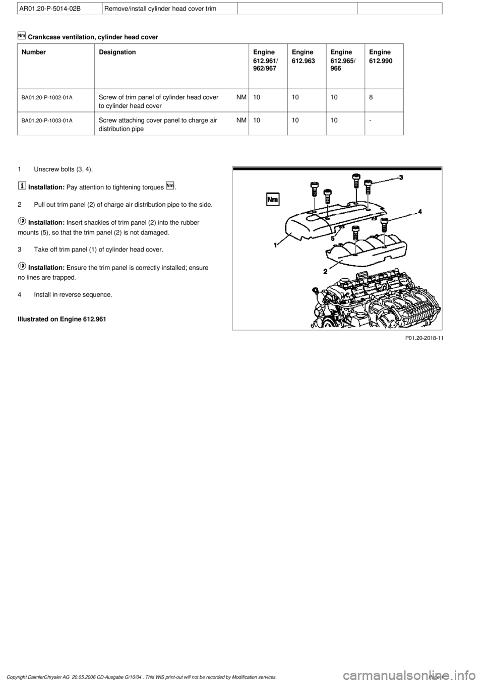
P01.20-2018-11
1
Unscrew bolts (3, 4).
Installation:
Pay attention to tightening torques
.
2
Pull out trim panel (2) of charge air distribution pipe to the side.
Installation:
Insert shackles of trim panel (2) into the rubber
mounts (5), so that the trim panel (2) is not damaged.
3
Take off trim panel (1) of cylinder head cover.
Installation:
Ensure the trim panel is correctly installed; ensure
no lines are trapped.
4
Install in reverse sequence.
Illustrated on Engine 612.961
Copyright DaimlerChrysler AG 20.05.2006 CD-Ausgabe G/10/04 . This WIS print-out will not be recorde
d by Modification services.
Page 1
Page 2105 of 4133

GF54.30-P-2002A
Display instruments, location / task / function
24.10.96
MODEL
129, 140 as of 1.6.96,
163, 168, 170,
202 as of 1.8.96,
208 up to 31.7.99,
210 as of 1.6.96 up to 30.6.99
Display
Type of data transmission
D
Outside temperature indicator (A1p4)
D
Fuel level gauge (A1p2)
D
Engine oil pressure gauge (A1p3), only
model 129 and model 140
D
Low windshield washer fluid level
indicator lamp (A1e13), model 163 as of
01.09.01
Direct lines
GF54.30-P-3004A
D
Total mileage odometer (A1h4)
D
Electronic speedometer (A1p8)
D
Tachometer (A1p5)
D
Coolant temperature gauge (A1p1)
D
Active service system (ASSYST)
D
Gear indicator (A1p12), only model 168
CAN data lines
GF54.30-P-3005A
D
Electronic clock
Internal
GF54.30-P-3011A
Copyright DaimlerChrysler AG 04.06.2006 CD-Ausgabe G/10/04 . This WIS print-out will not be recorde
d by Modification services.
Page 1
Page 2107 of 4133

GF54.30-P-3028GH
Displaying coolant level, function
28.6.99
MODEL
163 as of 1.3.99
Function prerequisite
Engine: ON
Function
If the coolant level drops below the minimum mark the low ECL
indicator lamp (A1p11) is illuminated.
To record the coolant level the instrument cluster (A1) is connected
direct to the
coolant level indicator electronic switch (S41)
via two
cables. The
coolant level indicator electronic switch (S41)
consists of two electrodes.
D
If the
level is correct
both electrodes are immersed in the
coolant. The coolant serves as a dielectric between the
electrodes.
D
If the coolant level is below the minimum mark the electrodes of
the sensor are no longer immersed in the coolant. There is only
air between the electrodes as a dielectric. Evaluation
The instrument cluster (A1) sends test pulses to the sensor for
a period of one millisecond. These pulses are deformed
differently depending on the dielectric (air or coolant).
The instrument cluster (A1) evaluates the pulse shape and, if
the coolant level is below the minimum (electrodes are
completely in air), actuates the low ECL indicator lamp (A1p11)
after a delay of
approx. 60 seconds
.
The delay serves to prevent the indicator lamp flickering due to
the coolant moving from side to side on corners or off-road.
Diagnosis
Diagnosis is carried out, as described in the Diagnosis Manual, via
the simulation of the
coolant level indicator electronic switch (S41)
by a resistance.
Coolant level switch,
location/task/design/function
GF54.30-P-4103GH
Copyright DaimlerChrysler AG 04.06.2006 CD-Ausgabe G/10/04 . This WIS print-out will not be recorde
d by Modification services.
Page 1
Page 2133 of 4133

AR47.10-P-4000GH
Empty fuel tank if fuel pump is faulty
28.10.97
MODEL
163.113 with ENGINE 612.963
MODEL
163.128 with ENGINE 628.963
MODEL
163.136 with ENGINE 111.977
MODEL
163.154 with ENGINE 112.942
MODEL
163.157 with ENGINE 112.970
MODEL
163.172 with ENGINE 113.942
MODEL
163.174 with ENGINE 113.981
MODEL
163.175 with ENGINE 113.965
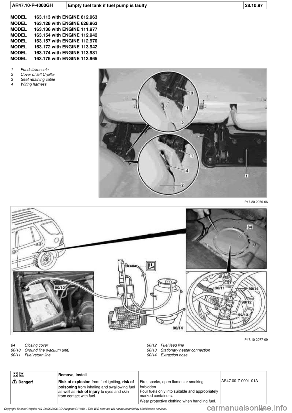
P47.20-2076-06
1
Fondsitzkonsole
2
Cover of left C-pillar
3
Seat retaining cable
4
Wiring harness
P47.10-2077-09
84
Closing cover
90/10
Ground line (vacuum unit)
90/11
Fuel return line
90/12
Fuel feed line
90/13
Stationary heater connection
90/14
Extraction hose
Remove, Install
Danger!
Risk of explosion
from fuel igniting,
risk of
poisoning
from inhaling and swallowing fuel
as well as
risk of injury
to eyes and skin
from contact with fuel.
Fire, sparks, open flames or smoking
forbidden.
Pour fuels only into suitable and appropriately
marked containers.
Wear protective clothing when handling fuel.
AS47.00-Z-0001-01A
Copyright DaimlerChrysler AG 28.05.2006 CD-Ausgabe G/10/04 . This WIS print-out will not be recorde
d by Modification services.
Page 1
Page 2139 of 4133

GF54.21-P-4106-01GH
Extended Activity Module - Task
n
The primary tasks of the Extended Activity Module (EAM, N10/1) are
as follows:
D
To control the door sill lights
D
To suppress the auto-dimming mirror function
D
To control the headlight cleaning system (HCS)
D
To control the rear window defroster
D
To control seat heating
D
To control the power supply via control console to tilt/sliding or
louvered sunroof switch
D
To control the PTC heater booster (R22/3)
D
To control the auxiliary fan (M4)
D
To read the cruise control switch (S40) and relay data to control
module (DAS, N73/1)
D
To read the contacts for wiper speed settings 1 and 2 on
combination switch (S4) for diagnosis.
To perform these tasks the Extended Activity Module (EAM, N10/1)
reads various signals and switch settings directly.
The Extended Activity Module (EAM, N10/1) interfaces with other
control modules via the engine compartment CAN.
-----------------------------------------------------------------------------------------
Diagnosis
Diagnosis is performed using the Star diagnostic tool. To facilitate
this task, the Extended Activity Module (EAM, N10/1) is equipped
with its own diagnostics cable.
This cable is also used to diagnose the
All Activity Module (AAM,
N10)
and the
transfer case control module (N78)
.
The Extended Activity Module (EAM, N10/1) is linked to the All
Activity Module (AAM, N10) via the
engine compartment CAN
.
Data communication between the All Activity Module (AAM,
N10) and the Extended Activity Module (EAM, N10/1) is
assumed by the
CAN (N10 - N10/1)
when terminal 15 is off.
The CAN (N10 - N10/1)
is an independent CAN bus located
between the All Activity Module (AAM, N10) and the Extended
Activity Module (EAM, N10/1).
No other
control modules are
connected to the CAN (N10 - N10/1).
-----------------------------------------------------------------------------------------
Details:
Door sill lights
When the front interior light is on and one of the front doors is open,
or when the rear interior light is on and one of the back doors is open,
the door sill lights for the open door will illuminate.
Headlight cleaning system (HCS)
Activating a separate switch causes the EAM to send a turn-on signal
to the HCS pump relay.
EAM will send an additional turn-on signal to the HCS pump relay
only after the cleaning operation is completed and a "rest period" of
approximately 2.5 sec. has passed.
Auto-dimming mirror function
The auto-dimming mirror function is suppressed when the interior
light is on or reverse gear is engaged.
Auto-dimming suppression for the outside rearview mirror (slave) is
activated by the inside rearview mirror (master).
Heater booster/PTC air heater for diesel engines
EAM monitors system voltage and adjusts heater booster capacity to
minimize load on battery.
Rear window defroster
EAM sets maximum ON time for rear window defroster depending
on outdoor temperature and current vehicle speed.
D
Standard ON time:
10 min.
D
Outdoor temperature < 5
o
C:
Additional 5 min.
D
Speed >80 km/h:
Additional 3 min.
Seat heating
Sets maximum seat heating time.
D
Setting 1: max. 20 min.
D
Setting 2: max. 5 min.
Tilt/sliding or louvered sunroofs
Signal via AAM2 allows operation of tilt/sliding or louvered sunroofs
when ignition is on (standard mode) or off (keyless mode).
Ignition authorization via CAN
The EAM issues ignition authorization to AAM2 via the engine
compartment CAN depending on the requirements of the engine
control unit in connection with the FBM.
Copyright DaimlerChrysler AG 18.05.2006 CD-Ausgabe G/10/04 . This WIS print-out will not be recorde
d by Modification services.
Page 1