Page 3473 of 4133

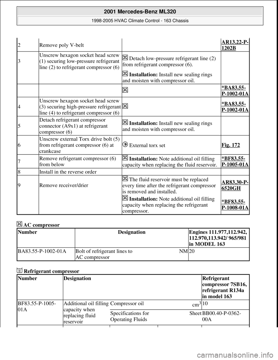
AC compressor
Refrigerant compressor
2Remove poly V-belt AR13.22-P-
1202B
3
Unscrew hexagon socket head screw
(1) securing low-pressure refrigerant
line (2) to refrigerant compressor (6) Detach low-pressure refrigerant line (2)
from refrigerant compressor (6).
Installation: Install new sealing rings
and moisten with compressor oil.
*BA83.55-
P-1002-01A
4
Unscrew hexagon socket head screw
(3) securing high-pressure refrigerant
line (4) to refrigerant compressor (6)
*BA83.55-
P-1002-01A
5
Detach refrigerant compressor
connector (A9x1) at refrigerant
compressor (6) Installation: Install new sealing rings
and moisten with compressor oil.
6
Unscrew external Torx drive bolt (5)
from refrigerant compressor (6) at
crankcase
External torx setFig. 172
7Remove refrigerant compressor (6)
from below Installation: Note additional oil filling
capacity when replacing the fluid reservoir.*BF83.55-
P-1005-01A
8Install in the reverse order
9Remove receiver/drier
The fluid reservoir must be replaced
every time after the refrigerant compressor
is removed and installed.AR83.30-P-
6520GH
Installation: Note additional oil filling
capacity when replacing the refrigerant
compressor.*BF83.55-
P-1008-01A
NumberDesignationEngines 111.977,112.942,
112.970,113.942/ 965/981
in MODEL 163
BA83.55-P-1002-01ABolt of refrigerant lines to
AC compressorNM20
NumberDesignationRefrigerant
compressor 7SB16,
refrigerant R134a
in model 163
BF83.55-P-1005-
01AAdditional oil filling
capacity when
replacing fluid
reservoirCompressor oilcm3 10
Specifications for
Operating FluidsSheetBB00.40-P-0362-
00A
2001 Mercedes-Benz ML320
1998-2005 HVAC Climate Control - 163 Chassis
me
Saturday, October 02, 2010 3:23:19 PMPage 229 © 2006 Mitchell Repair Information Company, LLC.
Page 3474 of 4133
Fig. 186: Identifying External Torx Set (001 589 76 09 00)
MAINTENANCE
REPLACE DUST FILTER FOR HEATIN G/AIR CONDITIONING - AP83.00-P-8381GH
MODEL 163.113 /128 /136 /154 /157 /172 /174 /175
Fig. 187: Identifying Dust Filter
BF83.55-P-1008-
01AAdditional oil filling
capacity when
replacing refrigerant
compressorCompressor oilcm3 20
Specifications for
Operating FluidsSheetBB00.40-P-0362-
00A
Remove/install
1Remove cover below instrument
panel (passenger side) Up to 31.08.99AR68.10-P-
1520GH
Remove/install cover below
instrument panel (right) As of 01.09.99AR68.10-P-
1520GI
2First unlatch retaining clamp (3), then
remove cover(2)
3Withdraw dust filter (1) downwards
(arrows) The dust filter must not be
cleaned; it must be replaced.
4Install in the reverse order
2001 Mercedes-Benz ML320
1998-2005 HVAC Climate Control - 163 Chassis
me
Saturday, October 02, 2010 3:23:19 PMPage 230 © 2006 Mitchell Repair Information Company, LLC.
Page 3762 of 4133

13
Disconnect coolant hose to coolant pump (8),
coolant hose from thermostat housing (9) and
coolant hose from coolant expansion tank
(10) at radiator
Hexagon socket wrench
*WH58.30-Z-1001-06A
Hexagon socket wrench
*WH58.30-Z-1002-06A
14
Detach air guides (12)
Installation:
Replace fastening clamps
(13)
15
Unscrew bolts (16) at condenser (17) to
radiator
Avoid deformation of condenser lines.
Do not disconnect lines.
16
Remove attachment parts (20) and rubber
shock absorber (21)
Installation:
Ensure, that the rubber
shock absorbers do not drop when installing
the radiator.
Replace fastening clamps.
17
Take off fluid reservoir of AC (14) at radiator
Place to the side with lines connected.
External torx set
*001589760900
18
Remove bracket of charge air pipe at left
radiator
Installation:
Insert bracket of charge air
pipe into the bracket at the radiator.
19
Remove radiator (15)
Installation:
When installing, the mounting
studs of the radiator must be inserted into the
rubber grommets of the lower crossmember.
20
Install in the reverse order
21
Check headlamp adjustment, correct if
necessary
e
Check and correct headlamp adjustment
AP82.10-P-8260A
22
Inspect cooling system for leaks
AR20.00-P-1010HA
23
Fill power steering pump and bleed
Danger!
Risk of accident
caused by vehicle starting
off by itself when engine is running.
Risk of
injury
caused by contusions and burns when
working in engine during starting procedure
Secure vehicle to prevent it from moving.
Wear closed and snug-fitting work clothes.
Do not grasp hot or rotating parts.
AS00.00-Z-0005-01A
24
Run engine and inspect for leaks
Crankcase ventilation, cylinder head cover
Number
Designation
Engine
612.963
BA01.20-P-1002-01A
Bolt, cylinder head cover trim panel to
cylinder head cover
Nm
10
BA01.20-P-1003-01A
Bolt, cover panel to charge air distribution
pipe
Nm
10
Power steering pump
Number
Designation
Model
163.113
BA46.30-P-1012-01A
Banjo bolt, power steering oil line to radiator
Nm
30
Cooling system
Number
Designation
Engine
612.963
BF20.00-P-1001-02E
Cooling system
Total capacity
Liter
Y
11.0
Copyright DaimlerChrysler AG 12.05.2006 CD-Ausgabe G/10/04 . This WIS print-out will not be recorde
d by Modification services.
Page 3