Page 43 of 4133
Fig. 32: Air Bag System Wiring Diagram (ML320)
1998 Mercedes-Benz ML320
AIR BAG RESTRAINT SYSTEM 1998 AIR BAG RESTRAINT SYSTEMS Mercedes-Benz
me
Saturday, October 02, 2010 3:33:14 PMPage 43 © 2006 Mitchell Repair Information Company, LLC.
Page 45 of 4133
Fig. 33: Air Bag System Wiring Diagram (S320, S420 & S500)
1998 Mercedes-Benz ML320
AIR BAG RESTRAINT SYSTEM 1998 AIR BAG RESTRAINT SYSTEMS Mercedes-Benz
me
Saturday, October 02, 2010 3:33:14 PMPage 45 © 2006 Mitchell Repair Information Company, LLC.
Page 47 of 4133
Fig. 34: Air Bag System Wiring Diagram (SLK230)
1998 Mercedes-Benz ML320
AIR BAG RESTRAINT SYSTEM 1998 AIR BAG RESTRAINT SYSTEMS Mercedes-Benz
me
Saturday, October 02, 2010 3:33:14 PMPage 47 © 2006 Mitchell Repair Information Company, LLC.
Page 367 of 4133
Fig. 1: Locating Restraint System Components (2000 E Class Shown; Others Are Similar)
Courtesy of MERCEDES-BENZ OF NORTH AMERICA.
SERVICING
SRS AIR BAG label on driver-side door latch post indicates SRS replacement date for driver and passenger air
bag units. All SRS components must be thoroughly insp ected, including wiring harness. Before component
replacement, check for SRS fault codes by performing system operation check. See SYSTEM OPERATION
CHECK . SRS service life is 10 years from manufactured date, or 10 years from SRS replacement date after
accident related repairs are completed.
SYSTEM OPERATION CHECK
SRS warning light indicates air ba g and Emergency Tensioning Retracto r (ETR) system readiness. Turn
ignition on. SRS warning light will illuminate, then turn off after approximately 4-20 seconds indicating system
is functioning properly. If SRS warning light does not illuminate, illuminates while driving or is continuously
illuminated, there is a system faul t. Repair malfunctioning system. See DIAGNOSTICS
.
AIR BAG SAFETY PRECAUTIONS
Observe following precautions when working with air bag systems:
When working around steering column components and be fore any repairs are performed, disable air bag
system. See DISABLING & ACTIVATING AIR BAG SYSTEM
.
Before straightening any damage to body, or before performing electrical arc-welding, disable air bag
system. See DISABLING & ACTIVATING AIR BAG SYSTEM
.
Always wear safety glasses and gloves when ha ndling a deployed air bag module. Air bag module may
contain sodium hydroxide deposits wh ich are irritating to the skin.
DO NOT repair any portion of SRS wiring harness.
Always handle air bag module with trim cover away from your body. Always place air bag module on
workbench with trim cover up, away from loose objects.
DO NOT expose any SRS component to temp eratures in excess of 212 F (100 C).
DO NOT expose any SRS component to cleaning agen ts such as solvents, gasoline, lye, etc.
DO NOT connect Hand-Held Tester (6511 0001 99) to Data Link Connector (DLC) with ignition on.
Damage to HHT may result.
DO NOT connect HHT (6511 0001 99) to vehicle if a battery charger is connected to vehicle battery.
Damage to HHT may result.
ADJUSTMENTS
If fixing screws were not used durin g clockspring removal or clockspring was rotated during removal, turn
clockspring clockwise until resistance is detectable. Turn clockspring counterclockwise 2-2.5 turns until fixing
screws can be unscrewed holdi ng clockspring in this position.
DISABLING & ACTIVATI NG AIR BAG SYSTEM
2001 Mercedes-Benz ML320
2000-01 ACCESSORIES/SAFETY EQUIPMENT Merc edes-Benz - Air Bag Restraint Systems
me
Saturday, October 02, 2010 3:44:45 PMPage 3 © 2006 Mitchell Repair Information Company, LLC.
Page 371 of 4133
1. Before proceeding, See AIR BAG SAFETY PRECAUTIONS . Disable air bag system. See
DISABLING & ACTIVATI NG AIR BAG SYSTEM
. Remove ignition key. Remove radio. Push up
and pull out heater control panel. Unplug 2 connectors. Remove scre w in middle of storage tray.
2. Bend up at top corners and lift out storage tray. Rem ove screws below storage tray. Lift wood trim panel
at rear, pull down and out of catches. Unplug swit ch connectors and remove wood trim panel. Unplug
connectors at control module and remove Torx mounting screws. Remove control module.
3. To install, reverse removal proce dure. Ensure SRS control module arro w points to front of vehicle. Set
parameters and program new SRS control module wi th Hand-Held Tester (965 589 00 01 00). Activate
air bag system. Perform system operation check to ensure system is functioning properly. See SYSTEM
OPERATION CHECK .
Removal & Installation (CLK & SLK)
1. Before proceeding, See AIR BAG SAFETY PRECAUTIONS . Disable air bag system. See
DISABLING & ACTIVATI NG AIR BAG SYSTEM
. Remove ignition key. Remove cover on center
console. Remove cover on shift lever. Remove ash tray housing with storage compartment at front of
center console. Unplug connectors at control module and remove Torx mounting screws. Remove control
module.
2. To install, reverse removal proce dure. Ensure SRS control module arro w points to front of vehicle. Set
parameters and program new SRS control module wi th Hand-Held Tester (965 589 00 01 00). Activate
air bag system. Perform system operation check to ensure system is functioning properly. See SYSTEM
OPERATION CHECK .
DRIVER-SIDE AIR BAG MODULE
Removal & Installation
1. Before proceeding, See AIR BAG SAFETY PRECAUTIONS . Disable air bag system. See
DISABLING & ACTIVATI NG AIR BAG SYSTEM
. Remove ignition key. Remove 2 Torx screws
from rear of steering wheel. Lift off air bag m odule enough to unplug connector from rear of module.
Place module away from work area, with pad facing upward.
2. To install, reverse removal procedure. Tighten Torx screws to specification. See TORQUE
SPECIFICATIONS . Activate air bag system. Perform system operation ch eck to ensure system is
functioning properly. See SYSTEM OPERATION CHECK
.
SIDE AIR BAG UNIT (DRIVER-SIDE & PASSENGER-SIDE)
Removal & Installation
1. Before proceeding, See AIR BAG SAFETY PRECAUTIONS . Disable air bag system. See
DISABLING & ACTIVATI NG AIR BAG SYSTEM
. Remove ignition key. Drill out rivets at
retaining plate of side air bag unit. Pull air bag unit out of door. Disconnect connector at driver-side air
bag squib. Remove unit from vehicle. See Fig. 2.
NOTE: Air bag module and steer
ing wheel must be replaced following a collision in
which air bag was deployed.
2001 Mercedes-Benz ML320
2000-01 ACCESSORIES/SAFETY EQUIPMENT Merc edes-Benz - Air Bag Restraint Systems
me
Saturday, October 02, 2010 3:44:45 PMPage 7 © 2006 Mitchell Repair Information Company, LLC.
Page 374 of 4133
Fig. 2: Removing Side Air Bag Unit (2000 Models)
Courtesy of MERCEDES-BENZ OF NORTH AMERICA.
SIDE AIR BAG SENSOR (DRIVER-SIDE & PASSENGER-SIDE)
Removal & Installation
1. Before proceeding, See AIR BAG SAFETY PRECAUTIONS . Disable air bag system. See
DISABLING & ACTIVATI NG AIR BAG SYSTEM
. Remove ignition key. On SLK 230, remove
door sill moulding. On all models, re move front seat. Fold floor covering in area toward rear. Unclip
connector on side bag sensor. Remove 2 mounting screws. Rem ove sensor from vehicle.
2. To install, reverse removal proce dure. Ensure that arrow on sensor poi nts toward outside. Perform system
operation check to ensure system is functioning properly. See SYSTEM OPERATION CHECK
.
2001 Mercedes-Benz ML320
2000-01 ACCESSORIES/SAFETY EQUIPMENT Merc edes-Benz - Air Bag Restraint Systems
me
Saturday, October 02, 2010 3:44:45 PMPage 10 © 2006 Mitchell Repair Information Company, LLC.
Page 376 of 4133
Fig. 3: Removing Side Air Bag Sensor (2000 E Class Shown; Others Are Similar)
Courtesy of MERCEDES-BENZ OF NORTH AMERICA.
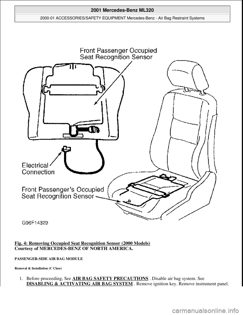
OCCUPIED SEAT RECOGNITION SENSOR
Removal & Installation
1. Before proceeding, See AIR BAG SAFETY PRECAUTIONS . Disable air bag system. See
DISABLING & ACTIVATI NG AIR BAG SYSTEM
.
2. Remove cover on front seat cushion. Remove i gnition key. Unclip connection for occupied seat
recognition sensor on seat connector block. Remove electrical connection lead from seat and pull upward
out of rubberized fiber matting. See Fig. 4
.
3. To install, lay out occupied seat recognition sens or uniformly on rubberized fiber matting. Fabric side
should point upward. Do not kink occupied seat sens or. Reverse removal procedure. Perform system
operation check to ensure s
ystem is functioning properly. See SYSTEM OPERATION CHECK.
2001 Mercedes-Benz ML320
2000-01 ACCESSORIES/SAFETY EQUIPMENT Merc edes-Benz - Air Bag Restraint Systems
me
Saturday, October 02, 2010 3:44:45 PMPage 12 © 2006 Mitchell Repair Information Company, LLC.
Page 377 of 4133
Fig. 4: Removing Occupied Seat Recognition Sensor (2000 Models)
Courtesy of MERCEDES-BENZ OF NORTH AMERICA.
PASSENGER-SIDE AIR BAG MODULE
Removal & Installation (C Class)
1. Before proceeding, See AIR BAG SAFETY PRECAUTIONS . Disable air bag system. See
DISABLING & ACTIVATI NG AIR BAG SYSTEM
. Remove ignition key. Remove instrument panel.
2001 Mercedes-Benz ML320
2000-01 ACCESSORIES/SAFETY EQUIPMENT Merc edes-Benz - Air Bag Restraint Systems
me
Saturday, October 02, 2010 3:44:45 PMPage 13 © 2006 Mitchell Repair Information Company, LLC.