1997 MERCEDES-BENZ ML320 Torque specification
[x] Cancel search: Torque specificationPage 3232 of 4133
Fig. 6: Removing Cooling Fans & Condenser
Courtesy of MERCEDES-BENZ OF NORTH AMERICA.
COOLING FANS
Removal & Installation
Remove headlight units. Remove upper frame crossmember, release hood release control cable and remove
crossmember. See Fig. 6
. Remove 2 cooling fans frame bolts on radiator. Disconnect cooling fan connector.
Release outside temperature sensor wiring harness. Pull up on cooling fan and remove. To install, reverse
removal procedure. Ensure cooling fan bottom guides are properly seated in lower mounts.
EVAPORATOR
Removal & Installation
Remove A/C housing unit. See A/C HOUSING UNIT . Remove expansion valve. See Fig. 5 . Discard "O"
rings. Disassemble A/C housing unit. Remove evaporator. Remove evaporator temperature sensor. To install,
reverse removal procedure. Use NEW "O" rings lubricated with refrigerant oil. If installing a new or repair
evaporator, add 1.35 ounces of NEW refrigerant oil to evaporator.
EXPANSION VALVE
Removal & Installation
1. Discharge A/C system, using approved refrigerant recovery/recycling equipment. Without disconnecting
coolant hoses, remove coolant expansion reservoir and set aside. Remove refrigerant line bracket and
loosen clamps. See Fig. 5
. Pull refrigerant lines out of expansion valve.
2. Remove expansion valve self-locking nut and discard. Remove expansion valve. Discard "O" rings. To
install, reverse removal procedure. Use NEW "O" rings lubricated with refrigerant oil. Tighten NEW self-
locking nut to specification. See TORQUE SPECIFICATIONS
.
INSTRUMENT PANEL & INSTRUMENT PANEL CARRIER
Removal & Installation
1. Secure vehicle against rolling. Set transmission selector to "D" position. Obtain radio security code.
Disconnect negative battery cable. Remove driver-side air bag.
2. Place match marks on steering wheel and steering shaft. Remove steering wheel, upper steering column
covers and combination switch. Remove instrument cluster cover frame. Remove one instrument panel
lower section bolt.
3. Remove screws in footwell from left side of instrument panel bottom section. Remove instrument panel
center section. Remove 4 A/C control panel screws and remove control panel. See Fig. 1
. Release pull
cables and disconnect connectors.
4. Remove screws from center section. Remove glove box. Remove screws in footwell from right side of
instrument panel bottom section. Remove entry courtesy lights. Remove end covers and screws.
5. Release 4 "A" clips between instrument panel bottom section and upper section. See Fig. 7
. Release
parkin
g brake release cable from handle. With assistance, remove instrument panel bottom section.
2001 Mercedes-Benz ML320
2000-01 MANUAL A/C-HEATER SYSTEMS ML 320, ML 430 & ML 55
me
Saturday, October 02, 2010 3:25:10 PMPage 21 © 2006 Mitchell Repair Information Company, LLC.
Page 3233 of 4133
6. Remove A-pillar panel trim. Remove instrument cluster. Remove defroster vent cover. Remove air vents
and side air nozzles. With assistance, remove upper instrument panel.
7. Remove passenger-side air bag. Remove right side lower instrument panel cover. Remove instrument
panel carrier screws from A/C housing unit. Remove left side lower instrument panel cover.
8. Remove insulating mat between steering column and instrument panel carrier. Remove steering column
bolts and nuts from instrument panel carrier. See Fig. 8
. Remove instrument panel carrier center tunnel
bolts. Disconnect steering column connectors.
9. Remove wiring harness from instrument panel carrier. Remove wiper washer system. Remove instrument
panel carrier nuts from engine compartment side of firewall.
10. Remove A-pillar bolt covers and remove instrument panel carrier A-pillar bolts. With assistance, remove
instrument panel carrier through passenger door. To install, reverse removal procedure.
11. Ensure instrument panel bottom section guide tongues "B" are seated into instrument panel upper section
mounts. See Fig. 8
. Tighten nuts and bolts to specification. See TORQUE SPECIFICATIONS .
Recode radio. See RECODING RADIO
under PROGRAMMING.
Fig. 7: Removing Instrument Panel Bottom Section
Courtesy of MERCEDES-BENZ OF NORTH AMERICA.
2001 Mercedes-Benz ML320
2000-01 MANUAL A/C-HEATER SYSTEMS ML 320, ML 430 & ML 55
me
Saturday, October 02, 2010 3:25:10 PMPage 22 © 2006 Mitchell Repair Information Company, LLC.
Page 3236 of 4133
Fig. 9: Replacing Intake Air Dust Filter
Courtesy of MERCEDES-BENZ OF NORTH AMERICA.
RECEIVER-DRIER
Removal & Installation
1. Discharge A/C system, using approved refrigerant recovery/recycling equipment. Remove headlight
units. Remove headlight units. Remove upper frame crossmember, release hood release control cable and
remove crossmember. See Fig. 6
.
2. Remove bolts from receiver-drier refrigerant lines. See Fig. 5
. Disconnect refrigerant lines from receiver-
drier. Plug exposed openings to protect A/C system from debris and moisture. Discard "O" rings. Loosen
receiver-drier clamp bolt. Remove receiver-drier. To install, reverse removal procedure.
3. When installing a new receiver-drier, add 0.34 ounce of NEW refrigerant oil to receiver-drier. Use NEW
"O" rings. Tighten refrigerant line bolts to specification. See TORQUE SPECIFICATIONS
.
TORQUE SPECIFICATIONS
TORQUE SPECIFICATIONS
WIRING DIAGRAMS
ApplicationFt. Lbs. (N.m)
Compressor Mounting Bolts15 (20)
Refrigerant Line-To-Compressor Bolt15 (20)
Refrigerant Line-To-Condenser Bolt15 (20)
Steering Column Bolt15 (20)
Steering Column Nut13 (18)
INCH Lbs. (N.m)
Expansion Valve Self-Locking Nut89 (10)
Refrigerant Line-To-Receiver-Drier Bolt89 (10)
2001 Mercedes-Benz ML320
2000-01 MANUAL A/C-HEATER SYSTEMS ML 320, ML 430 & ML 55
me
Saturday, October 02, 2010 3:25:10 PMPage 25 © 2006 Mitchell Repair Information Company, LLC.
Page 3884 of 4133
Verify ground connection integrity between engine, body, battery and generator. Check for damaged wiring
harnesses and/or switches. Check fo r a broken or partially broken wire inside insulation, which could cause
system malfunction but prove good in a continuity/vol tage check with system disconnected. Ensure any
aftermarket electronic e quipment is properly installed. If fault is found, repair as necessary. If no fault is found,
check for conditions that might cause an intermittent situation.
SERVICE PRECAUTIONS
BATTERY DISCONNECT/CONNECT
Disconnect/Connect Procedures
1. Turn ignition off. Open engine hood. After opening ve hicle wait at least 4 minutes before disconnecting
battery or alarm wi ll be triggered.
2. Disconnect negative battery cable (1) and insulate cable lug to prevent unwanted contact with ground
point (W16/4). See Fig. 1
.
3. To connect, reverse disconnect procedur e. Tighten nut (5) to specification. See TORQUE
SPECIFICATIONS .
4. Perform basic programming, read Diagnostic Tr ouble Code (DTC) memory and erase DTCs from
memory. See BASIC PROGRAMMING
and RETRIEVING & ERASING DIAGNOSTIC
TROUBLE CODES .
NOTE: Numbers and letters in text refe
r to numbers and letters in figures.
2001 Mercedes-Benz ML320
2001-04 STARTING & CHARGING SYSTEMS Starters - 163 Chassis
me
Saturday, October 02, 2010 3:19:47 PMPage 2 © 2006 Mitchell Repair Information Company, LLC.
Page 3891 of 4133
Fig. 4: Connecting Hand Held Tester Scan Tool To OBD-II Data Link Connector
Courtesy of MERCEDES-BENZ OF NORTH AMERICA.
TESTING
Starter malfunctions may cause a Di agnostic Trouble Codes (DTCs) to be stored in Motor Electronics
Sequential Fuel Injection (ME-SFI) sy stem. After repairs are completed check for and erase any DTCs stored in
(ME-SFI) system. See appropriate SE LF-DIAGNOSTICS article in ENGINE PERFORMANCE. If cause of
starter malfunction is not engine pe rformance related, replace starter.
REMOVAL & INSTALLATION
STARTER
Removal & Installation
1. Disconnect and shield negative battery cable. See BATTERY DISCONNECT/CONNECT under
SERVICE PRECAUTIONS.
2. Remove nut (2) for inner fender. See Fig. 5
. Pull front and rear section of inner fender (1) downward.
Move inner fender away inward and downward. Pull toward outside over wheel. DO NOT damage fender
cutout or paint.
3. On vehicles with 112 engine, remove nut (6) at shield (5) of left engine mount and take out shield. See
Fig. 6
.
4. On all vehicles, disconnect circuit 30 (1) and circuit 50 (2) cables from starter. See Fig. 6
. Remove bolts
(3) for starter-to-crankcase. Take starter (M1) out to the side.
5. If replacing starter on vehicles with manual transmission, check ring gear at flywheel for wear and
damage. If replacing starter on vehicles with auto matic transmission, check ring gear on drive plate for
wear and damage. Repair or repl ace damaged parts as necessary.
6. To install, reverse removal proce dure. Replace bolts with locking splines, micro-encapsulated bolts and
self-locking nuts. Mating thread of mi cro-encapsulated bolts must be cleaned to remove all residue of old
bolt locking compound. Tighten fasteners to specification. See TORQUE SPECIFICATIONS
. Connect
battery. See BATTERY DISCONNECT/CONNECTunder SERVICE PRECAUTIONS.
NOTE: Numbers and letters in text refe
r to numbers and letters in figures.
2001 Mercedes-Benz ML320
2001-04 STARTING & CHARGING SYSTEMS Starters - 163 Chassis
me
Saturday, October 02, 2010 3:19:47 PMPage 9 © 2006 Mitchell Repair Information Company, LLC.
Page 3893 of 4133
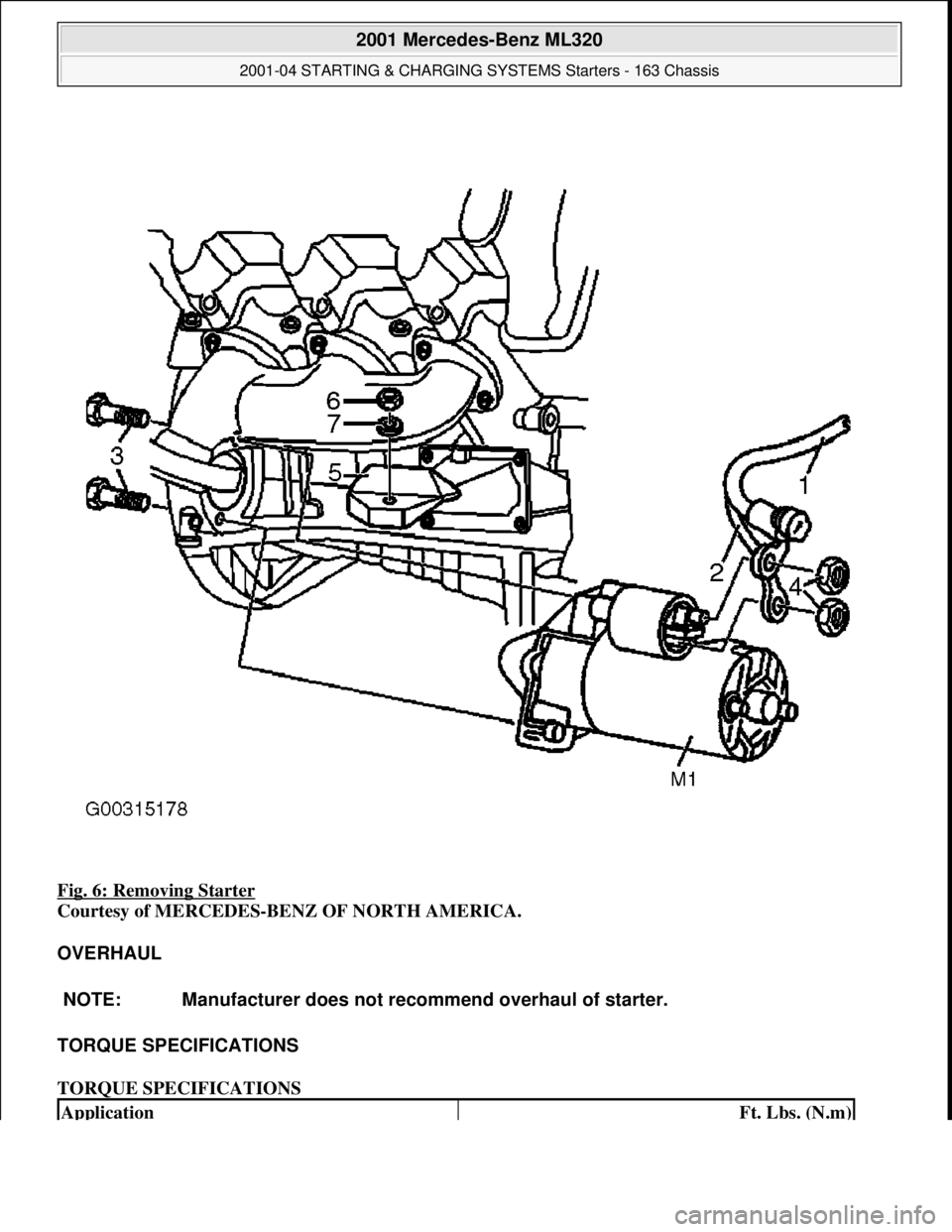
Fig. 6: Removing Starter
Courtesy of MERCEDES-BENZ OF NORTH AMERICA.
OVERHAUL
TORQUE SPECIFICATIONS
TORQUE SPECIFICATIONS
NOTE: Manufacturer does not r ecommend overhaul of starter.
ApplicationFt. Lbs. (N.m)
2001 Mercedes-Benz ML320
2001-04 STARTING & CHARGING SYSTEMS Starters - 163 Chassis
me
Saturday, October 02, 2010 3:19:47 PMPage 11 © 2006 Mitchell Repair Information Company, LLC.