1997 MERCEDES-BENZ ML320 coolant reservoir
[x] Cancel search: coolant reservoirPage 2356 of 4133

1998-2005 ENGINE
Complete engine - 163 Chassis
GENERAL INFORMATION
DETERMINE LOSS OF PR ESSURE AT CYLINDER - AH01.00-N-1300-02A
All engine
If an increased pressure loss was found with the cylinde r leak tightness tester, inspect engine by listening at
cylinder head gasket, air intake area, exhaust, oil fi ller opening and prechamber or spark plug bores of the
adjacent cylinder or cylinders.
Check the coolant in the coolant expansion reservoir for the formation of air bubbles.
Possible causes for the pressure loss are: 1. Outlet of air through prechamber or spark plug bo re of adjacent cylinder or cylinders, air bubbles
in coolant expansion reservoir:
pressure loss at cylinder head gasket
2. Outlet of air through air intake area:
For inspecting by listening, open throttle valve pressure loss at inlet valve(s)
3. Outlet of air through exhaust:
pressure loss at exhaust valve(s)
4. Outlet of air through oil filler opening:
pressure loss through pistons and piston rings
It is possible to pinpoint the pressure loss of the rele vant cylinder by spraying with engine oil. Engine oil
seals off the gap between piston and cylinder briefly.
If a reduced pressure loss now occurs for a short time, th e cause is very likely to be at the pistons, piston rings
or cylinder contact surface of the relevant cylinder.
Determining the cause can be falsified by the position of th e piston ring joints. If suspicion exists that the loss o
f
pressure is caused by the piston ring joints being positioned directly one above the other, fit parts to engine and
repeat test after running engine for a short time.
GENERAL INFORMATION ON INSPECTING CYLINDER WALLS - AH01.00-P-0300-01A
2001 Mercedes-Benz ML320
1998-2005 ENGINE Complete engine - 163 Chassis
2001 Mercedes-Benz ML320
1998-2005 ENGINE Complete engine - 163 Chassis
me
Saturday, October 02, 2010 3:17:55 PMPage 1 © 2006 Mitchell Repair Information Company, LLC.
me
Saturday, October 02, 2010 3:18:01 PMPage 1 © 2006 Mitchell Repair Information Company, LLC.
Page 2396 of 4133
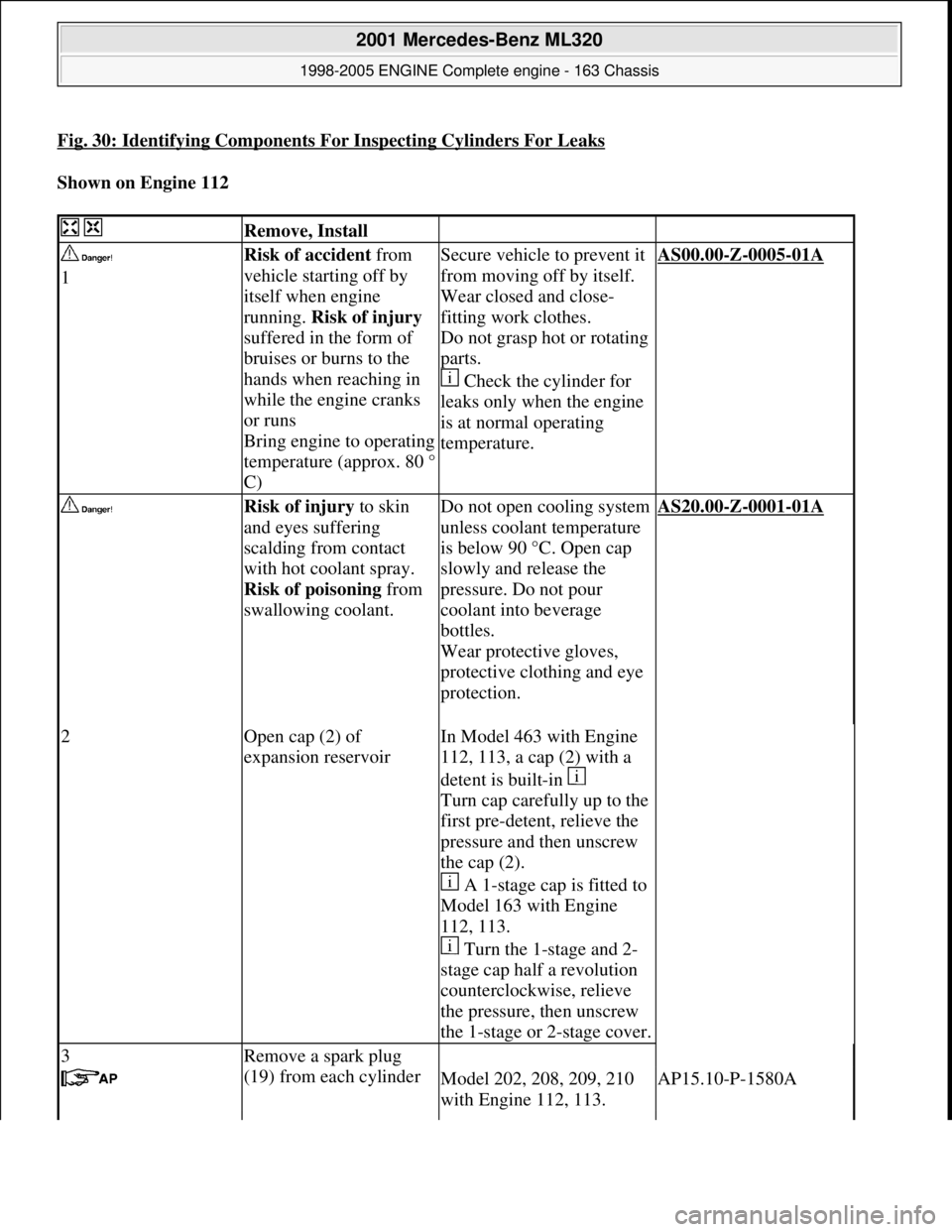
Fig. 30: Identifying Components For Inspecting Cylinders For Leaks
Shown on Engine 112
Remove, Install
1Risk of accident from
vehicle starting off by
itself when engine
running. Risk of injury
suffered in the form of
bruises or burns to the
hands when reaching in
while the engine cranks
or runs
Bring engine to operating
temperature (approx. 80 °
C)Secure vehicle to prevent it
from moving off by itself.
Wear closed and close-
fitting work clothes.
Do not grasp hot or rotating
parts.
Check the cylinder for
leaks only when the engine
is at normal operating
temperature.AS00.00-Z-0005-01A
Risk of injury to skin
and eyes suffering
scalding from contact
with hot coolant spray.
Risk of poisoning from
swallowing coolant.
Do not open cooling system
unless coolant temperature
is below 90 °C. Open cap
slowly and release the
pressure. Do not pour
coolant into beverage
bottles.
Wear protective gloves,
protective clothing and eye
protection.
AS20.00-Z-0001-01A
2Open cap (2) of
expansion reservoirIn Model 463 with Engine
112, 113, a cap (2) with a
detent is built-in
Turn cap carefully up to the
first pre-detent, relieve the
pressure and then unscrew
the cap (2).
A 1-stage cap is fitted to
Model 163 with Engine
112, 113.
Turn the 1-stage and 2-
stage cap half a revolution
counterclockwise, relieve
the pressure, then unscrew
the 1-stage or 2-stage cover.
3Remove a spark plug
(19) from each cylinder
Model 202, 208, 209, 210
with Engine 112, 113.AP15.10-P-1580A
2001 Mercedes-Benz ML320
1998-2005 ENGINE Complete engine - 163 Chassis
me
Saturday, October 02, 2010 3:17:56 PMPage 40 © 2006 Mitchell Repair Information Company, LLC.
Page 2410 of 4133
202,
Engine 602.983, 612.966 in MODEL 461,
Engine 628.962, 612.965, 606.964, 112.945,
113.962 /982 in MODEL 463,
Engine 111, 112, 611.962, 612.962 in model
203,
Engine 112, 113, 611.961, 612.961, 613.961 in
MODEL 210,
Engine 112 in model 170,
Engine 112 in MODEL 220,
Engine 113 in MODEL 211, 215,220,
Engine 112 in MODEL 208,
Engine 112, 113, 612.963, 628.963 in MODEL
163,
Engine 112.923/943, 113.961 in MODEL 129,
Engine 137, 275 in MODEL 215, 220,
Engine 613.960, 628.960 in MODEL 220,
Engine 113.992 in model 230.474,
Engine 271 in model 209, 203,
Engine 285.950 in model 240.078 /178,
Engine 612.967 in model 209.316,
Engine 648 in model 220
Engine 112.951 in model
639.601/603 /605 /701 /703 /705 /801 /803 /805
Engine 646.983 /984 in model
639. /605 /701 /703/705/801 /803/805
Engine 646.982 in model
639.601 /603 /605 /701 /703 /705
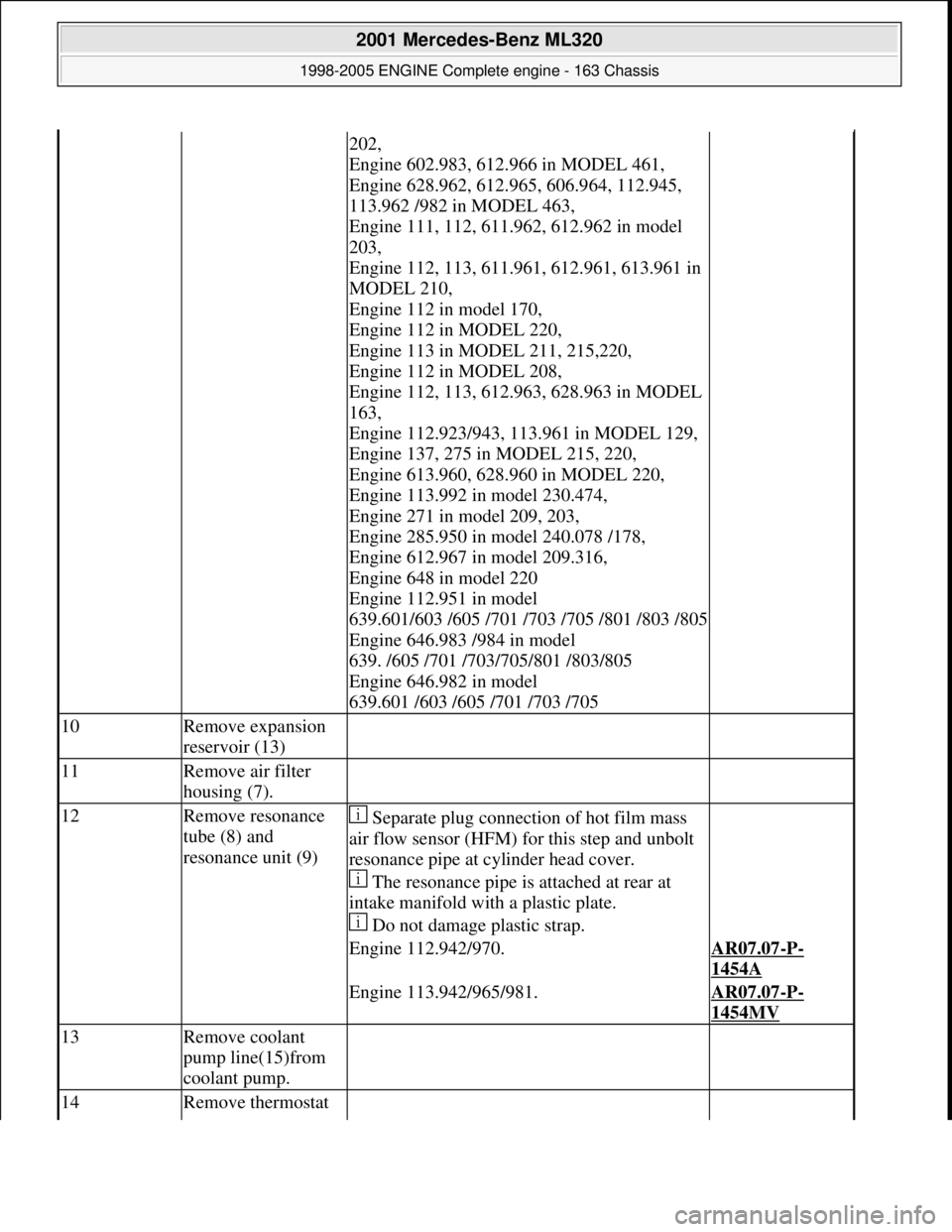
10Remove expansion
reservoir (13)
11Remove air filter
housing (7).
12Remove resonance
tube (8) and
resonance unit (9) Separate plug connection of hot film mass
air flow sensor (HFM) for this step and unbolt
resonance pipe at cy linder head cover.
The resonance pipe is attached at rear at
intake manifold with a plastic plate.
Do not damage plastic strap.
Engine 112.942/970.AR07.07-P-
1454A
Engine 113.942/965/981.AR07.07-P-
1454MV
13Remove coolant
pump line(15)from
coolant pump.
14Remove thermostat
2001 Mercedes-Benz ML320
1998-2005 ENGINE Complete engine - 163 Chassis
me
Saturday, October 02, 2010 3:17:56 PMPage 54 © 2006 Mitchell Repair Information Company, LLC.
Page 2459 of 4133

Engine 113 in model 129, 202, 208, 210
Engine 113 (except 113.965/981) in model 163
24.1Remove oil
reservoir on
power steering
pump (11)Model 163
Removal: Extract oil from rese rvoir. Remove circlip.
Installation: Replace sealing ring. Ch eck that circlip is
correctly seated.
Power steering -
checking and
correcting oil
level AP46.00-P-
4611BB
Hand pumpFig. 95
24.2Detach power
steering pump
(11) with oil
reservoir. Do not disconnect lines.
*BA46.30-P-
1005-01A
*BA46.30-P-
1010-01A
*BA46.30-P-
1010-01C
25.1Detach guide
pulley at timing
case coverModel 230.474
*BA13.25-P-
1008-01D
25.2Take off guide
pulley (15) at
coolant pump Except model 230.474
Take plastic cover off guide pulley.
*BA20.10-P-
1001-01C
*BA20.10-P-
1001-01M
26.1Remove
compressorEngine 112.960 in model 170.466
Engine 113.992 in model 230.474AR09.50-P-
4705SVK
27Remove air pump
(20)Engine 112 (except 112.960) in model 170
Engine 112 in 163, 202, 208, 210
Engines 113 in 163, 202, 208, 210AR14.30-P-
7251A
Engine 112.922 in model 220.063AR14.30-P-
7251AA
Engine 112.923 in model 129.059
Engine 112.943 in model 129.064
Engine 112.944 in model 220.065 /165
Engine 112.972 in model 220.067 /167
Engine 112.975 in model 220.087 /187
Engine 113.941 in models 220.070/170
Engine 113.948 in model 220.083 /183
Engine 113.960 in model 220.075/175
Engine 113.960 in model 215.375
Engine 113.961 in model 129.068
Engine 113.963 in models 230.475
Engine 113.966 in model 220.084 /184
2001 Mercedes-Benz ML320
1998-2005 ENGINE Complete engine - 163 Chassis
me
Saturday, October 02, 2010 3:17:57 PMPage 103 © 2006 Mitchell Repair Information Company, LLC.
Page 2584 of 4133
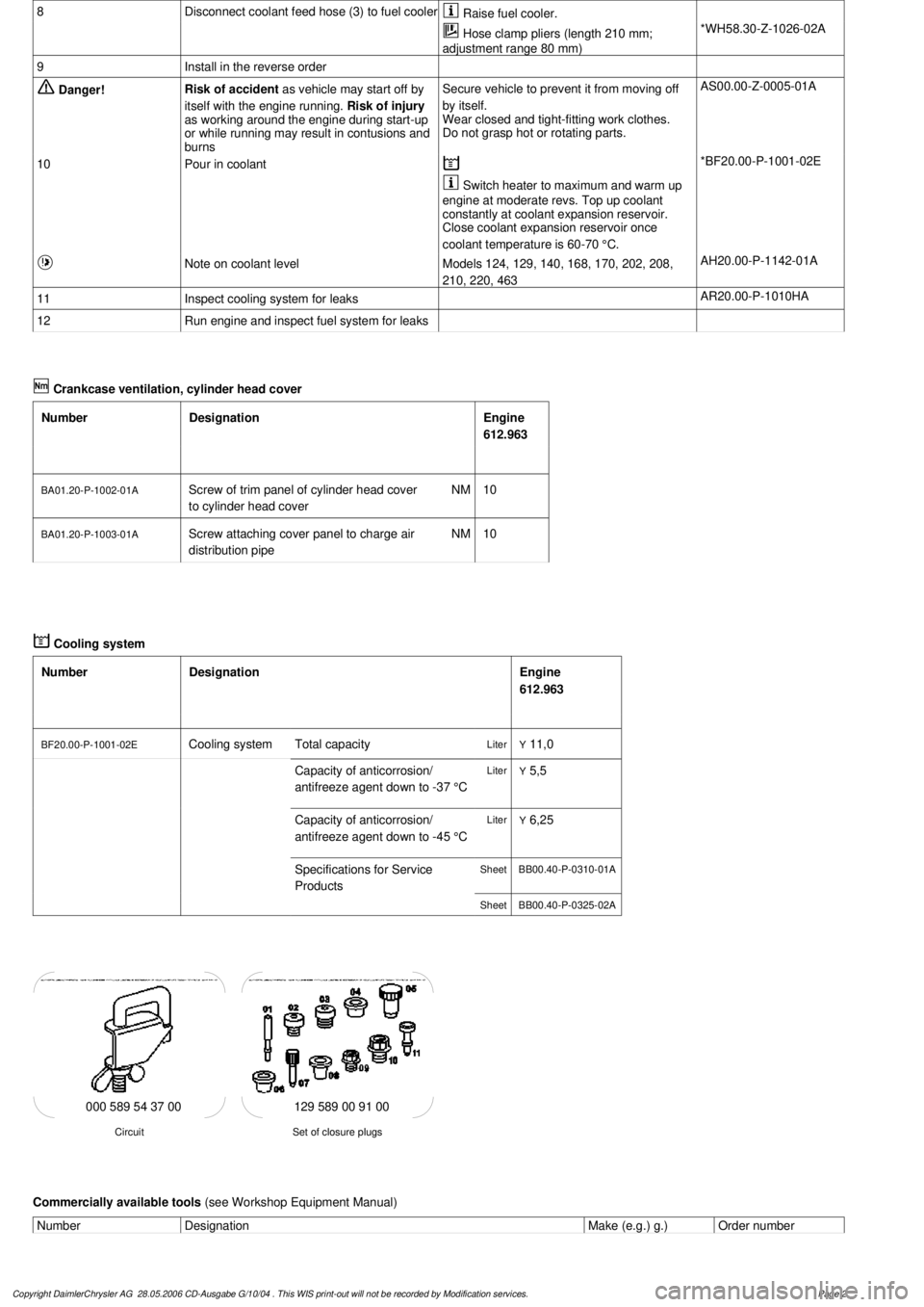
8
Disconnect coolant feed hose (3) to fuel cooler
Raise fuel cooler.
Hose clamp pliers (length 210 mm;
adjustment range 80 mm)
*WH58.30-Z-1026-02A
9
Install in the reverse order
Danger!
Risk of accident
as vehicle may start off by
itself with the engine running.
Risk of injury
as working around the engine during start-up
or while running may result in contusions and
burns
Secure vehicle to prevent it from moving off
by itself.
Wear closed and tight-fitting work clothes.
Do not grasp hot or rotating parts.
AS00.00-Z-0005-01A
10
Pour in coolant
*BF20.00-P-1001-02E
Switch heater to maximum and warm up
engine at moderate revs. Top up coolant
constantly at coolant expansion reservoir.
Close coolant expansion reservoir once
coolant temperature is 60-70 °C.
Note on coolant level
Models 124, 129, 140, 168, 170, 202, 208,
210, 220, 463
AH20.00-P-1142-01A
11
Inspect cooling system for leaks
AR20.00-P-1010HA
12
Run engine and inspect fuel system for leaks
Crankcase ventilation, cylinder head cover
Number
Designation
Engine
612.963
BA01.20-P-1002-01A
Screw of trim panel of cylinder head cover
to cylinder head cover
NM
10
BA01.20-P-1003-01A
Screw attaching cover panel to charge air
distribution pipe
NM
10
Cooling system
Number
Designation
Engine
612.963
BF20.00-P-1001-02E
Cooling system
Total capacity
Liter
Y
11,0
Capacity of anticorrosion/
antifreeze agent down to -37 °C
Liter
Y
5,5
Capacity of anticorrosion/
antifreeze agent down to -45 °C
Liter
Y
6,25
Specifications for Service
Products
SheetBB00.40-P-0310-01A
SheetBB00.40-P-0325-02A
129 589 00 91 00
Set of closure plugs
Circuit
000 589 54 37 00
Commercially available tools
(see Workshop Equipment Manual)
Number
Designation
Make (e.g.) g.)
Order number
Copyright DaimlerChrysler AG 28.05.2006 CD-Ausgabe G/10/04 . This WIS print-out will not be recorde
d by Modification services.
Page 2
Page 3226 of 4133
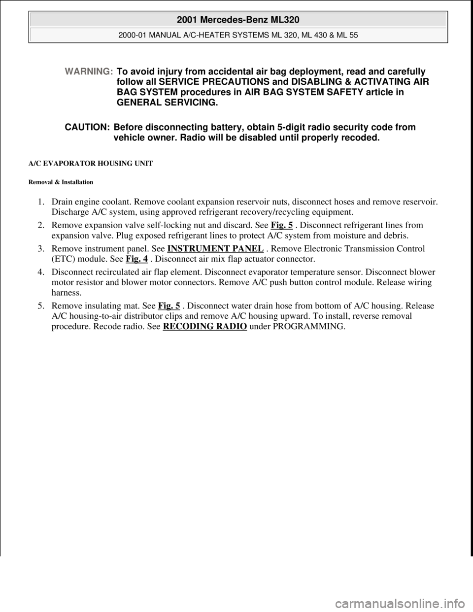
A/C EVAPORATOR HOUSING UNIT
Removal & Installation
1. Drain engine coolant. Remove coolant expansion reservoir nuts, disconnect hoses and remove reservoir.
Discharge A/C system, using approved refrigerant recovery/recycling equipment.
2. Remove expansion valve self-locking nut and discard. See Fig. 5
. Disconnect refrigerant lines from
expansion valve. Plug exposed refrigerant lines to protect A/C system from moisture and debris.
3. Remove instrument panel. See INSTRUMENT PANEL
. Remove Electronic Transmission Control
(ETC) module. See Fig. 4
. Disconnect air mix flap actuator connector.
4. Disconnect recirculated air flap element. Disconnect evaporator temperature sensor. Disconnect blower
motor resistor and blower motor connectors. Remove A/C push button control module. Release wiring
harness.
5. Remove insulating mat. See Fig. 5
. Disconnect water drain hose from bottom of A/C housing. Release
A/C housing-to-air distributor clips and remove A/C housing upward. To install, reverse removal
procedure. Recode radio. See RECODING RADIO
under PROGRAMMING. WARNING:To avoid injury from accidental air bag deployment, read and carefully
follow all SERVICE PRECAUTIONS and DISABLING & ACTIVATING AIR
BAG SYSTEM procedures in AIR BAG SYSTEM SAFETY article in
GENERAL SERVICING.
CAUTION: Before disconnecting battery, obtain 5-digit radio security code from
vehicle owner. Radio will be disabled until properly recoded.
2001 Mercedes-Benz ML320
2000-01 MANUAL A/C-HEATER SYSTEMS ML 320, ML 430 & ML 55
me
Saturday, October 02, 2010 3:25:10 PMPage 15 © 2006 Mitchell Repair Information Company, LLC.
Page 3232 of 4133
Fig. 6: Removing Cooling Fans & Condenser
Courtesy of MERCEDES-BENZ OF NORTH AMERICA.
COOLING FANS
Removal & Installation
Remove headlight units. Remove upper frame crossmember, release hood release control cable and remove
crossmember. See Fig. 6
. Remove 2 cooling fans frame bolts on radiator. Disconnect cooling fan connector.
Release outside temperature sensor wiring harness. Pull up on cooling fan and remove. To install, reverse
removal procedure. Ensure cooling fan bottom guides are properly seated in lower mounts.
EVAPORATOR
Removal & Installation
Remove A/C housing unit. See A/C HOUSING UNIT . Remove expansion valve. See Fig. 5 . Discard "O"
rings. Disassemble A/C housing unit. Remove evaporator. Remove evaporator temperature sensor. To install,
reverse removal procedure. Use NEW "O" rings lubricated with refrigerant oil. If installing a new or repair
evaporator, add 1.35 ounces of NEW refrigerant oil to evaporator.
EXPANSION VALVE
Removal & Installation
1. Discharge A/C system, using approved refrigerant recovery/recycling equipment. Without disconnecting
coolant hoses, remove coolant expansion reservoir and set aside. Remove refrigerant line bracket and
loosen clamps. See Fig. 5
. Pull refrigerant lines out of expansion valve.
2. Remove expansion valve self-locking nut and discard. Remove expansion valve. Discard "O" rings. To
install, reverse removal procedure. Use NEW "O" rings lubricated with refrigerant oil. Tighten NEW self-
locking nut to specification. See TORQUE SPECIFICATIONS
.
INSTRUMENT PANEL & INSTRUMENT PANEL CARRIER
Removal & Installation
1. Secure vehicle against rolling. Set transmission selector to "D" position. Obtain radio security code.
Disconnect negative battery cable. Remove driver-side air bag.
2. Place match marks on steering wheel and steering shaft. Remove steering wheel, upper steering column
covers and combination switch. Remove instrument cluster cover frame. Remove one instrument panel
lower section bolt.
3. Remove screws in footwell from left side of instrument panel bottom section. Remove instrument panel
center section. Remove 4 A/C control panel screws and remove control panel. See Fig. 1
. Release pull
cables and disconnect connectors.
4. Remove screws from center section. Remove glove box. Remove screws in footwell from right side of
instrument panel bottom section. Remove entry courtesy lights. Remove end covers and screws.
5. Release 4 "A" clips between instrument panel bottom section and upper section. See Fig. 7
. Release
parkin
g brake release cable from handle. With assistance, remove instrument panel bottom section.
2001 Mercedes-Benz ML320
2000-01 MANUAL A/C-HEATER SYSTEMS ML 320, ML 430 & ML 55
me
Saturday, October 02, 2010 3:25:10 PMPage 21 © 2006 Mitchell Repair Information Company, LLC.
Page 3295 of 4133
The fresh air/recirculated air flap shuts off the supply of recirculated air.
Fresh air is drawn in.
Recirculation mode
The fresh air/recirculated air flap shuts off the supply of fresh air. Air is drawn in from the passenger
compartment.
HEATER CORE, LOCATION/PURPOSE/FUNCTION - GF83.20-P-2108GC
MODEL 163, 168
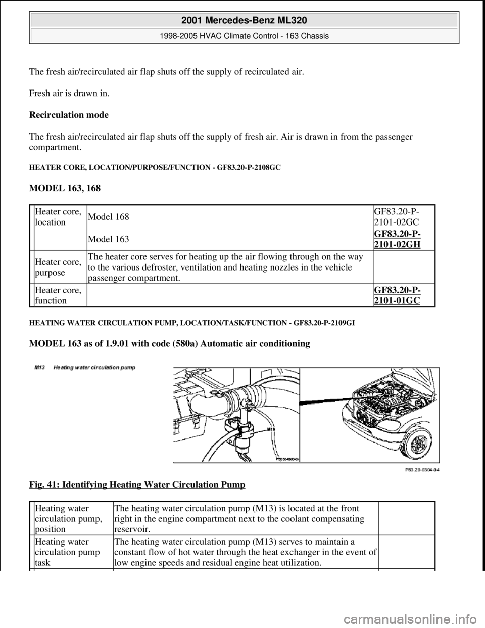
HEATING WATER CIRCULATION PUMP, LOCATION/TASK/FUNCTION - GF83.20-P-2109GI
MODEL 163 as of 1.9.01 with code (580a) Automatic air conditioning
Fig. 41: Identifying Heating Water Circulation Pump
Heater core,
locationModel 168GF83.20-P-
2101-02GC
Model 163GF83.20-P-
2101-02GH
Heater core,
purposeThe heater core serves for heating up the air flowing through on the way
to the various defroster, ventilation and heating nozzles in the vehicle
passenger compartment.
Heater core,
function GF83.20-P-
2101-01GC
Heating water
circulation pump,
positionThe heating water circulation pump (M13) is located at the front
right in the engine compartment next to the coolant compensating
reservoir.
Heating water
circulation pump
taskThe heating water circulation pump (M13) serves to maintain a
constant flow of hot water through the heat exchanger in the event of
low engine speeds and residual engine heat utilization.
2001 Mercedes-Benz ML320
1998-2005 HVAC Climate Control - 163 Chassis
me
Saturday, October 02, 2010 3:23:15 PMPage 51 © 2006 Mitchell Repair Information Company, LLC.