1997 MERCEDES-BENZ ML320 engine
[x] Cancel search: enginePage 2608 of 4133
AR47.10-P-4100GH
Remove fuel tank
10.3.97
MODEL
163.113 with ENGINE 612.963
MODEL
163.128 with ENGINE 628.963
MODEL
163.136 with ENGINE 111.977
MODEL
163.154 with ENGINE 112.942
MODEL
163.157 with ENGINE 112.970
MODEL
163.172 with ENGINE 113.942
MODEL
163.175 with ENGINE 113.965
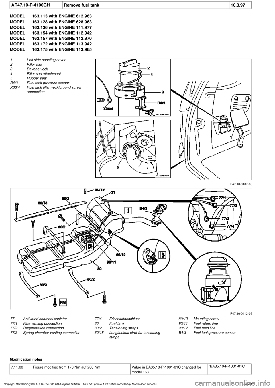
P47.10-0407-06
1
Left side paneling cover
2
Filler cap
3
Bayonet lock
4
Filler cap attachment
5
Rubber seal
B4/3 Fuel tank pressure sensor
X36/4
Fuel tank filler neck/ground screw
connection
P47.10-0413-09
77
Activated charcoal canister
77/1
Fine venting connection
77/2
Regeneration connection
77/3
Spring chamber venting connection
80/19
Mounting screw
90/11
Fuel return line
90/12
Fuel feed line
B4/3 Fuel tank pressure sensor
77/4
Frischluftanschluss
80
Fuel tank
80/2
Tensioning straps
80/18
Longitudinal strut for tensioning
straps
Modification notes
7.11.00
Figure modified from 170 Nm auf 200 Nm
Value in BA35.10-P-1001-01C changed for
model 163
*BA35.10-P-1001-01C
Copyright DaimlerChrysler AG 28.05.2006 CD-Ausgabe G/10/04 . This WIS print-out will not be recorde
d by Modification services.
Page 1
Page 2609 of 4133

Remove, Install
Danger!
Risk of explosion
from fuel igniting,
risk of
poisoning
from inhaling and swallowing fuel
as well as
risk of injury
to eyes and skin
from contact with fuel.
Fire, sparks, open flames or smoking
forbidden.
Pour fuels only into suitable and appropriately
marked containers.
Wear protective clothing when handling fuel.
AS47.00-Z-0001-01A
1
Drain fuel tank
Via fuel pump. NOT for model 163.113/128.
AR47.10-P-4001GH
If fuel pump faulty, and model 163.113/128.
AR47.10-P-4000GH
*BF47.10-P-1001-01A
2
Unscrew filler cap (2) and detach from filler
cap attachment (4)
3.1
Remove left seat of 3rd seat row
If installed. See owner's manual
4
Unclip cover of left-hand side panel (1)
5.1
Detach fuel lines of expansion reservoir and
separate from filler neck
As of VIN A289565. NOT for model
163.113/128.
6
Detach fuel filler neck from guide funnel
Installation:
Check O-ring and replace if
necessary. Ensure that the bayonet-lock
remains above
the pressure sensor.
Ensure it is correctly located when installed.
Open bayonet lock (3) to do this.
7
Pull filler neck through toward interior
Screw on cap again in order to avoid fuel
flowing out.
8.1
Remove fuel tank pressure sensor (B4/3)
Only USA version
AR47.10-P-8022GH
9.1
Detach bolted connection of fuel tank filler
neck/ground (X36/4) from filler neck
NOT for model 163.113/128.
10.1
Cut cable strap for retaining clips of fuel lines
at filler neck and remove retaining clips
As of VIN A289565. NOT for model
163.113/128.
Danger!
Risk of fatal accident
from vehicle slipping
or toppling off the lift platform
Align vehicle between the columns of lifting
platform and position the four support plates
below the support strongpoints specified by
the vehicle manufacturer.
AS00.00-Z-0010-01A
11
Place the vehicle on lifting platform
AR00.60-P-1000GH
12
Separate rubber seal (5) from underside of
vehicle and remove filler neck from interior
Do not damage fuel lines at filler neck.
13
Remove left rear wheel
e
Removing and installing wheels, rotating if
necessary
AP40.10-P-4050GH
14
Remove spare wheel and spare wheel carrier
complete
NOT in the case of spare wheel
holder/spare wheel, code 849.
15
Cut a large safety cable strap for filler neck at
bracket on longitudinal frame member
16
Remove bracket from longitudinal frame
member
17
Disconnect connection for regeneration (77/2)
and fresh air connection (77/4) on activated
charcoal canister (77)
Installation
: Connect up lines as per
connection diagram:
#
Engine 111
AR47.30-P-8212-01GJ
Engines 112, 113
AR47.30-P-8212-01GI
Engines 112, 113 version
I
AR47.30-P-8212-01GH
Charcoal canister and fuel tank form a
single unit.
NOT for model 163.113/128.
18
Detach vent hose
At rear differential to rear of activated
charcoal reservoir.
19
Remove rear exhaust system heat shield.
Do not damage boot at rear axle shaft.
20
Disconnect rear propeller shaft at differential
Installation:
Install new self-locking bolts.
Tie up propeller shaft e.g. using welding
wire
Heat bolts with hot air fan to facilitate
removing. Mark propeller shaft and differential
gear flange for correct installed position.
*BA41.10-P-1002-01C
Copyright DaimlerChrysler AG 28.05.2006 CD-Ausgabe G/10/04 . This WIS print-out will not be recorde
d by Modification services.
Page 2
Page 2612 of 4133
AR47.10-P-8022GH
Remove/install fuel tank pressure sensor
18.3.97
MODEL
163.154 with ENGINE 112.942 with CODE (494a) USA version
MODEL
163.157 with ENGINE 112.970 with CODE (494a) USA version
MODEL
163.172 with ENGINE 113.942 with CODE (494a) USA version
MODEL
163.174 with ENGINE 113.981 with CODE (494a) USA version
MODEL
163.175 with ENGINE 113.965 with CODE (494a) USA version
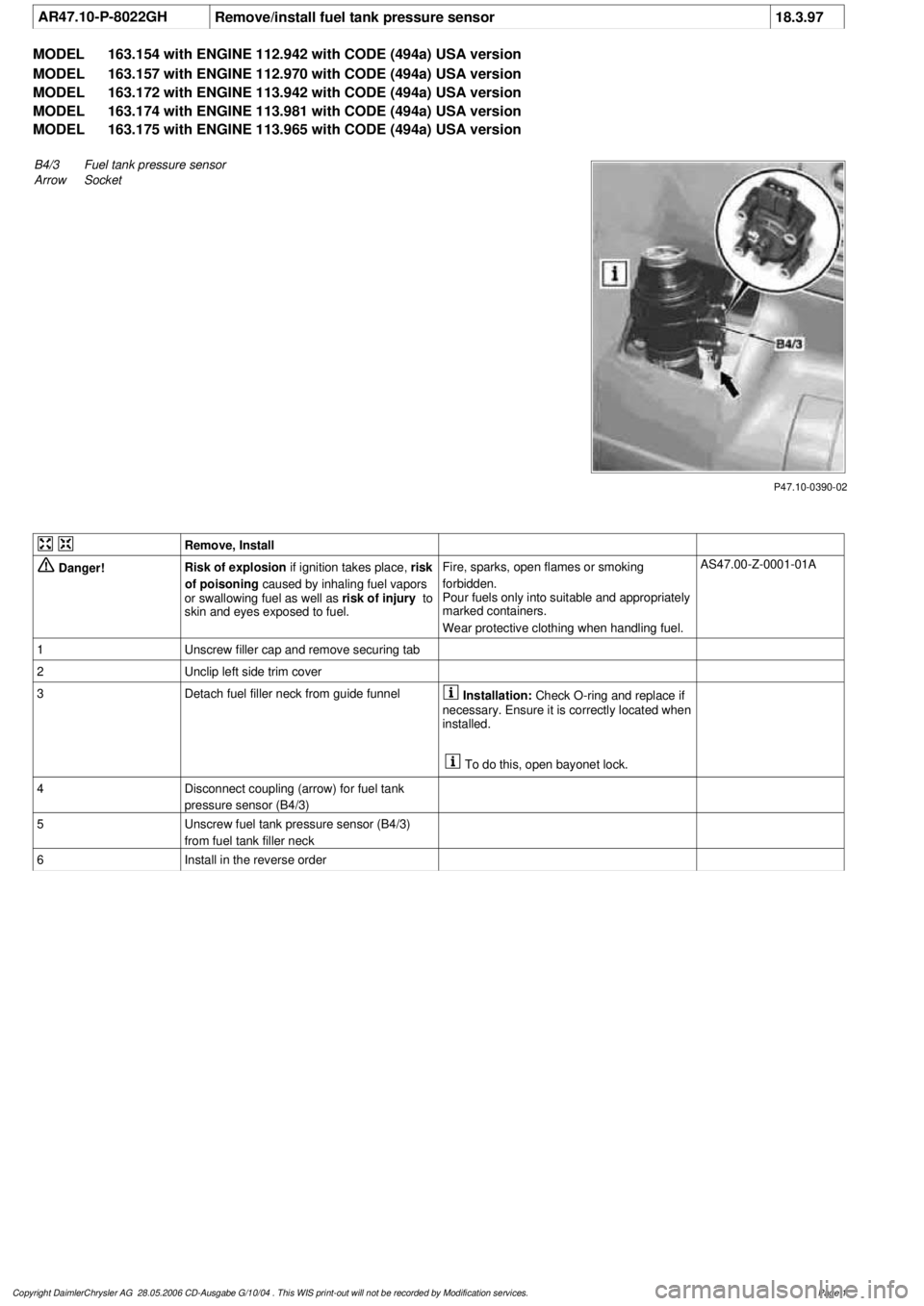
P47.10-0390-02
B4/3Fuel tank pressure sensor
Arrow
Socket
Remove, Install
Danger!
Risk of explosion
if ignition takes place,
risk
of poisoning
caused by inhaling fuel vapors
or swallowing fuel as well as
risk of injury
to
skin and eyes exposed to fuel.
Fire, sparks, open flames or smoking
forbidden.
Pour fuels only into suitable and appropriately
marked containers.
Wear protective clothing when handling fuel.
AS47.00-Z-0001-01A
1
Unscrew filler cap and remove securing tab
2
Unclip left side trim cover
3
Detach fuel filler neck from guide funnel
Installation:
Check O-ring and replace if
necessary. Ensure it is correctly located when
installed.
To do this, open bayonet lock.
4
Disconnect coupling (arrow) for fuel tank
pressure sensor (B4/3)
5
Unscrew fuel tank pressure sensor (B4/3)
from fuel tank filler neck
6
Install in the reverse order
Copyright DaimlerChrysler AG 28.05.2006 CD-Ausgabe G/10/04 . This WIS print-out will not be recorde
d by Modification services.
Page 1
Page 2615 of 4133
2001-04 ELECTRICAL
Fuses & Circuit Breakers - 163 Chassis
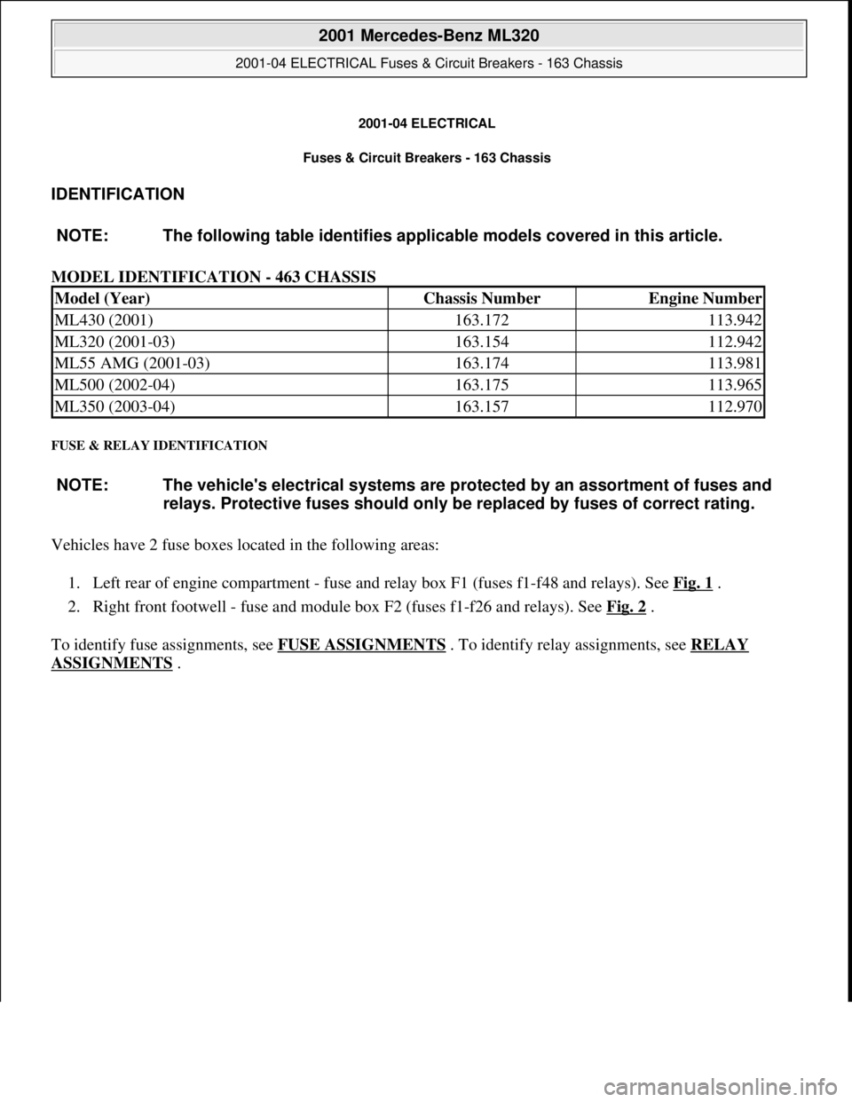
IDENTIFICATION
MODEL IDENTIFICATION - 463 CHASSIS
FUSE & RELAY IDENTIFICATION
Vehicles have 2 fuse boxes located in the following areas:
1. Left rear of engine compartment - fuse and relay box F1 (fuses f1-f48 and relays). See Fig. 1
.
2. Right front footwell - fuse and module box F2 (fuses f1-f26 and relays). See Fig. 2
.
To identify fuse assignments, see FUSE ASSIGNMENTS
. To identify relay assignments, see RELAY
ASSIGNMENTS . NOTE: The following table identifies applicable models covered in this article.
Model (Year)Chassis NumberEngine Number
ML430 (2001)163.172113.942
ML320 (2001-03)163.154112.942
ML55 AMG (2001-03)163.174113.981
ML500 (2002-04)163.175113.965
ML350 (2003-04)163.157112.970
NOTE: The vehicle's electrical systems are protected by an assortment of fuses and
relays. Protective fuses should only be replaced by fuses of correct rating.
2001 Mercedes-Benz ML320
2001-04 ELECTRICAL Fuses & Circuit Breakers - 163 Chassis
2001 Mercedes-Benz ML320
2001-04 ELECTRICAL Fuses & Circuit Breakers - 163 Chassis
me
Saturday, October 02, 2010 3:22:06 PMPage 1 © 2006 Mitchell Repair Information Company, LLC.
me
Saturday, October 02, 2010 3:22:09 PMPage 1 © 2006 Mitchell Repair Information Company, LLC.
Page 2650 of 4133
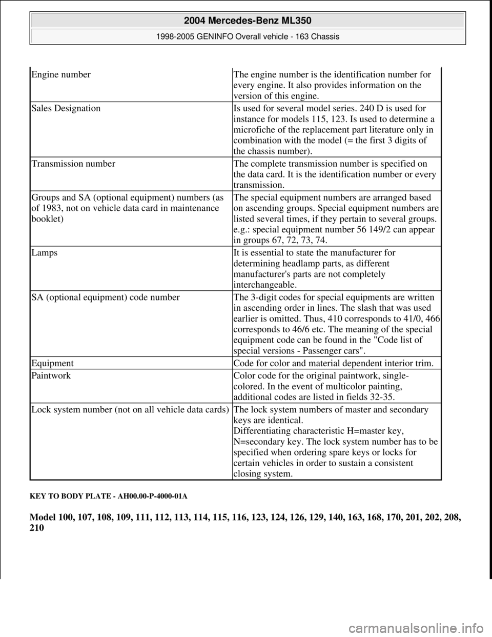
KEY TO BODY PLATE - AH00.00-P-4000-01A
Model 100, 107, 108, 109, 111, 112, 113, 114, 115, 116, 123, 124, 126, 129, 140, 163, 168, 170, 201, 202, 208,
210
Engine numberThe engine number is the identification number for
every engine. It also provides information on the
version of this engine.
Sales DesignationIs used for several model series. 240 D is used for
instance for models 115, 123. Is used to determine a
microfiche of the replacement part literature only in
combination with the model (= the first 3 digits of
the chassis number).
Transmission numberThe complete transmission number is specified on
the data card. It is the identification number or every
transmission.
Groups and SA (optional equipment) numbers (as
of 1983, not on vehicle data card in maintenance
booklet)The special equipment numbers are arranged based
on ascending groups. Special equipment numbers are
listed several times, if they pertain to several groups.
e.g.: special equipment number 56 149/2 can appear
in groups 67, 72, 73, 74.
LampsIt is essential to state the manufacturer for
determining headlamp parts, as different
manufacturer's parts are not completely
interchangeable.
SA (optional equipment) code numberThe 3-digit codes for special equipments are written
in ascending order in lines. The slash that was used
earlier is omitted. Thus, 410 corresponds to 41/0, 466
corresponds to 46/6 etc. The meaning of the special
equipment code can be found in the "Code list of
special versions - Passenger cars".
EquipmentCode for color and material dependent interior trim.
PaintworkColor code for the original paintwork, single-
colored. In the event of multicolor painting,
additional codes are listed in fields 32-35.
Lock system number (not on all vehicle data cards)The lock system numbers of master and secondary
keys are identical.
Differentiating characteristic H=master key,
N=secondary key. The lock system number has to be
specified when ordering spare keys or locks for
certain vehicles in order to sustain a consistent
closing system.
2004 Mercedes-Benz ML350
1998-2005 GENINFO Overall vehicle - 163 Chassis
me
Saturday, October 02, 2010 3:47:44 PMPage 5 © 2006 Mitchell Repair Information Company, LLC.
Page 2652 of 4133
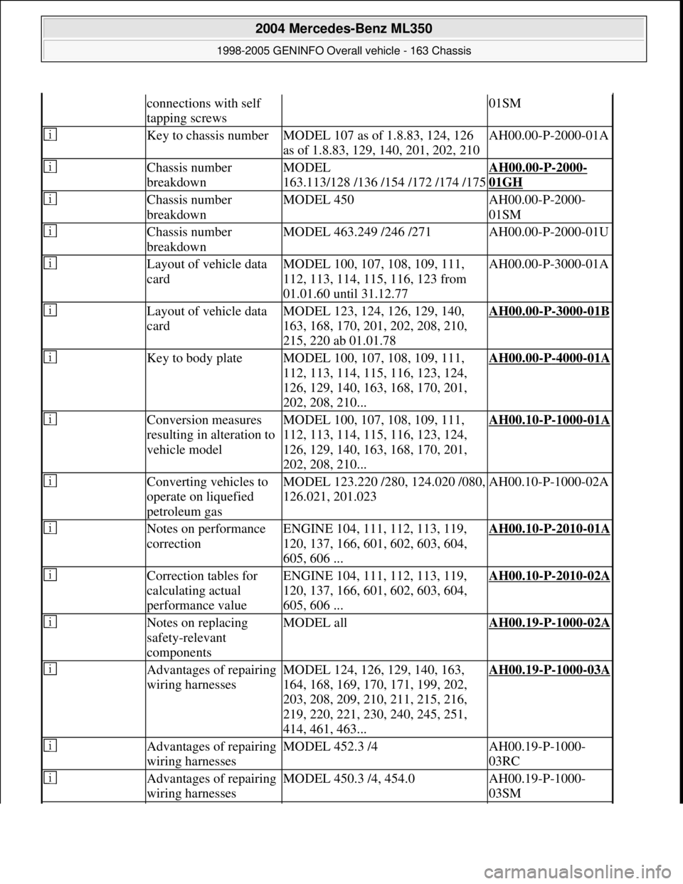
connections with self
tapping screws01SM
Key to chassis numberMODEL 107 as of 1.8.83, 124, 126
as of 1.8.83, 129, 140, 201, 202, 210AH00.00-P-2000-01A
Chassis number
breakdownMODEL
163.113/128 /136 /154 /172 /174 /175AH00.00-P-2000-
01GH
Chassis number
breakdownMODEL 450AH00.00-P-2000-
01SM
Chassis number
breakdownMODEL 463.249 /246 /271AH00.00-P-2000-01U
Layout of vehicle data
cardMODEL 100, 107, 108, 109, 111,
112, 113, 114, 115, 116, 123 from
01.01.60 until 31.12.77AH00.00-P-3000-01A
Layout of vehicle data
cardMODEL 123, 124, 126, 129, 140,
163, 168, 170, 201, 202, 208, 210,
215, 220 ab 01.01.78AH00.00-P-3000-01B
Key to body plateMODEL 100, 107, 108, 109, 111,
112, 113, 114, 115, 116, 123, 124,
126, 129, 140, 163, 168, 170, 201,
202, 208, 210...AH00.00-P-4000-01A
Conversion measures
resulting in alteration to
vehicle modelMODEL 100, 107, 108, 109, 111,
112, 113, 114, 115, 116, 123, 124,
126, 129, 140, 163, 168, 170, 201,
202, 208, 210...AH00.10-P-1000-01A
Converting vehicles to
operate on liquefied
petroleum gasMODEL 123.220 /280, 124.020 /080,
126.021, 201.023AH00.10-P-1000-02A
Notes on performance
correctionENGINE 104, 111, 112, 113, 119,
120, 137, 166, 601, 602, 603, 604,
605, 606 ...AH00.10-P-2010-01A
Correction tables for
calculating actual
performance valueENGINE 104, 111, 112, 113, 119,
120, 137, 166, 601, 602, 603, 604,
605, 606 ...AH00.10-P-2010-02A
Notes on replacing
safety-relevant
componentsMODEL allAH00.19-P-1000-02A
Advantages of repairing
wiring harnessesMODEL 124, 126, 129, 140, 163,
164, 168, 169, 170, 171, 199, 202,
203, 208, 209, 210, 211, 215, 216,
219, 220, 221, 230, 240, 245, 251,
414, 461, 463...AH00.19-P-1000-03A
Advantages of repairing
wiring harnessesMODEL 452.3 /4AH00.19-P-1000-
03RC
Advantages of repairing
wiring harnessesMODEL 450.3 /4, 454.0AH00.19-P-1000-
03SM
2004 Mercedes-Benz ML350
1998-2005 GENINFO Overall vehicle - 163 Chassis
me
Saturday, October 02, 2010 3:47:44 PMPage 7 © 2006 Mitchell Repair Information Company, LLC.
Page 2655 of 4133
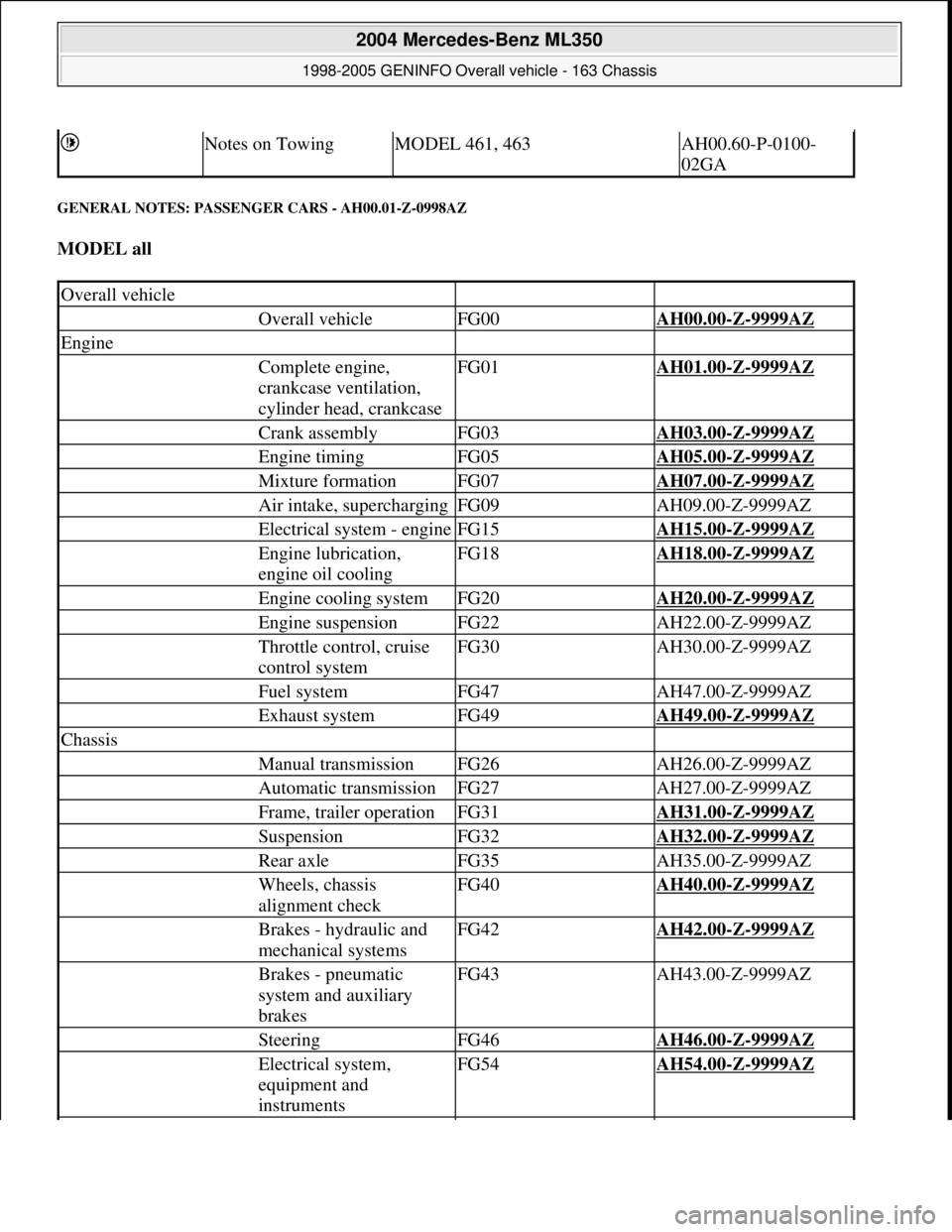
GENERAL NOTES: PASSENGER CARS - AH00.01-Z-0998AZ
MODEL all
Notes on TowingMODEL 461, 463AH00.60-P-0100-
02GA
Overall vehicle
Overall vehicleFG00AH00.00-Z-9999AZ
Engine
Complete engine,
crankcase ventilation,
cylinder head, crankcaseFG01AH01.00-Z-9999AZ
Crank assemblyFG03AH03.00-Z-9999AZ
Engine timingFG05AH05.00-Z-9999AZ
Mixture formationFG07AH07.00-Z-9999AZ
Air intake, superchargingFG09AH09.00-Z-9999AZ
Electrical system - engineFG15AH15.00-Z-9999AZ
Engine lubrication,
engine oil coolingFG18AH18.00-Z-9999AZ
Engine cooling systemFG20AH20.00-Z-9999AZ
Engine suspensionFG22AH22.00-Z-9999AZ
Throttle control, cruise
control systemFG30AH30.00-Z-9999AZ
Fuel systemFG47AH47.00-Z-9999AZ
Exhaust systemFG49AH49.00-Z-9999AZ
Chassis
Manual transmissionFG26AH26.00-Z-9999AZ
Automatic transmissionFG27AH27.00-Z-9999AZ
Frame, trailer operationFG31AH31.00-Z-9999AZ
SuspensionFG32AH32.00-Z-9999AZ
Rear axleFG35AH35.00-Z-9999AZ
Wheels, chassis
alignment checkFG40AH40.00-Z-9999AZ
Brakes - hydraulic and
mechanical systemsFG42AH42.00-Z-9999AZ
Brakes - pneumatic
system and auxiliary
brakesFG43AH43.00-Z-9999AZ
SteeringFG46AH46.00-Z-9999AZ
Electrical system,
equipment and
instrumentsFG54AH54.00-Z-9999AZ
2004 Mercedes-Benz ML350
1998-2005 GENINFO Overall vehicle - 163 Chassis
me
Saturday, October 02, 2010 3:47:44 PMPage 10 © 2006 Mitchell Repair Information Company, LLC.
Page 2656 of 4133
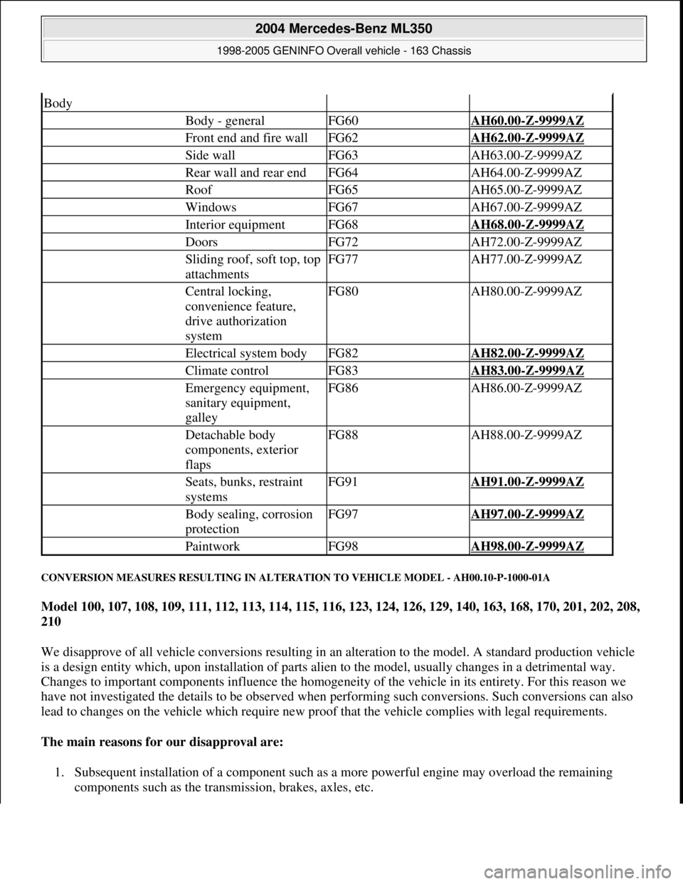
CONVERSION MEASURES RESULTING IN ALTERATION TO VEHICLE MODEL - AH00.10-P-1000-01A
Model 100, 107, 108, 109, 111, 112, 113, 114, 115, 116, 123, 124, 126, 129, 140, 163, 168, 170, 201, 202, 208,
210
We disapprove of all vehicle conversions resulting in an alteration to the model. A standard production vehicle
is a design entity which, upon installation of parts alien to the model, usually changes in a detrimental way.
Changes to important components influence the homogeneity of the vehicle in its entirety. For this reason we
have not investigated the details to be observed when performing such conversions. Such conversions can also
lead to changes on the vehicle which require new proof that the vehicle complies with legal requirements.
The main reasons for our disapproval are:
1. Subsequent installation of a component such as a more powerful engine may overload the remaining
components such as the transmission, brakes, axles, etc.
Body
Body - generalFG60AH60.00-Z-9999AZ
Front end and fire wallFG62AH62.00-Z-9999AZ
Side wallFG63AH63.00-Z-9999AZ
Rear wall and rear endFG64AH64.00-Z-9999AZ
RoofFG65AH65.00-Z-9999AZ
WindowsFG67AH67.00-Z-9999AZ
Interior equipmentFG68AH68.00-Z-9999AZ
DoorsFG72AH72.00-Z-9999AZ
Sliding roof, soft top, top
attachmentsFG77AH77.00-Z-9999AZ
Central locking,
convenience feature,
drive authorization
systemFG80AH80.00-Z-9999AZ
Electrical system bodyFG82AH82.00-Z-9999AZ
Climate controlFG83AH83.00-Z-9999AZ
Emergency equipment,
sanitary equipment,
galleyFG86AH86.00-Z-9999AZ
Detachable body
components, exterior
flapsFG88AH88.00-Z-9999AZ
Seats, bunks, restraint
systemsFG91AH91.00-Z-9999AZ
Body sealing, corrosion
protectionFG97AH97.00-Z-9999AZ
PaintworkFG98AH98.00-Z-9999AZ
2004 Mercedes-Benz ML350
1998-2005 GENINFO Overall vehicle - 163 Chassis
me
Saturday, October 02, 2010 3:47:44 PMPage 11 © 2006 Mitchell Repair Information Company, LLC.