1997 MAZDA MX-5 lock
[x] Cancel search: lockPage 50 of 514

OPERATION
TCM
TCM receives information from various input devices and uses this information to control solenoids on
transmission valve body for transmission shifting and torque converter clutch engagement.
TCM automatically switches from NORMAL mode to POWER mode corresponding to driving condition in
"D" range. Upshifts and downshifts are performed at a higher speed in POWER mode than in NORMAL mode.
TCM contains a self-diagnostic system, which will store Diagnostic Trouble Codes (DTC) if a failure or
problem exists in electronic control system. DTC can be retrieved to determine problem area. See SELF-
DIAGNOSTIC SYSTEM . TCM is located under left side of instrument panel, above fuse block.
TCM INPUT DEVICES & SIGNALS
4th Gear Inhibit Signal
Signal is input to TCM when cruise control is on. Signal detects when difference between target speed and
actual speed exceeds specification.
HOLD Switch
HOLD switch delivers input to TCM to indicate gears preferred by operator. Switch is located on shift lever
handle. HOLD switch is canceled when ignition switch is turned off.
Input/Turbine Speed Sensor
Sensor is a magnetic pick-up type pulse generator that monitors input shaft speed. AC waveform is input to
TCM by output speed sensor. Sensor is located on front of transmission, back of converter housing.
Throttle Position (TP) Sensor
TP sensor delivers an input signal to TCM indicating throttle valve position (opening). TP sensor is located on
side of throttle body.
Transmission Range Switch
Transmission range switch delivers an input signal to TCM indicating shift lever position. Switch is located on
side of transmission.
Transmission Fluid Temperature (TFT) Sensor
TFT sensor is threaded into cooler line banjo mounting on side of transmission case. Sensor sends signal to
TCM indicating fluid temperature.
Vehicle Speed Sensor
1997 Mazda MX-5 Miata
1997 AUTOMATIC TRANSMISSIONS NC4A-EL Electronic Controls
Microsoft
Sunday, July 05, 2009 1:35:03 PMPage 2 © 2005 Mitchell Repair Information Company, LLC.
Page 51 of 514

Sensor is a cable driven pulse generator that is part of speedometer. Pulse signals are sent to TCM.
TCM OUTPUT DEVICES
HOLD Indicator Light
Receives signal from TCM to indicate switch position.
Inhibitor Signal
When shift selector lever is moved from Park or Neutral to another gear, signal is sent from TCM to ECM to
regulate fuel injection volume for shift shock prevention.
Shift Solenoids & 3-2 Control Solenoid
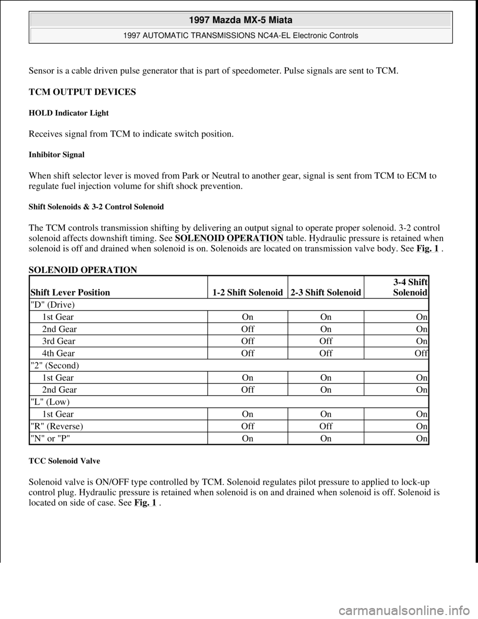
The TCM controls transmission shifting by delivering an output signal to operate proper solenoid. 3-2 control
solenoid affects downshift timing. See SOLENOID OPERATION
table. Hydraulic pressure is retained when
solenoid is off and drained when solenoid is on. Solenoids are located on transmission valve body. See Fig. 1
.
SOLENOID OPERATION
TCC Solenoid Valve
Solenoid valve is ON/OFF type controlled by TCM. Solenoid regulates pilot pressure to applied to lock-up
control plug. Hydraulic pressure is retained when solenoid is on and drained when solenoid is off. Solenoid is
located on side of case. See Fig. 1
.
Shift Lever Position1-2 Shift Solenoid2-3 Shift Solenoid
3-4 Shift
Solenoid
"D" (Drive)
1st GearOnOnOn
2nd GearOffOnOn
3rd GearOffOffOn
4th GearOffOffOff
"2" (Second)
1st GearOnOnOn
2nd GearOffOnOn
"L" (Low)
1st GearOnOnOn
"R" (Reverse)OffOffOn
"N" or "P"OnOnOn
1997 Mazda MX-5 Miata
1997 AUTOMATIC TRANSMISSIONS NC4A-EL Electronic Controls
Microsoft
Sunday, July 05, 2009 1:35:03 PMPage 3 © 2005 Mitchell Repair Information Company, LLC.
Page 55 of 514

CLEARING CODES
To clear DTC stored in TCM, use scan tool. See scan tool instruction manual. Road test vehicle.
COMPONENT LOCATION
COMPONENT LOCATION
COMPONENT CONNECTOR IDENTIFICATION
P0706 Transmission Range Sensor Range/Performance
P0710 (2) TFT Sensor Malfunction
P0711 (2) TFT Sensor Range/Performance
P0715 Input/Turbine Speed Sensor
P0725 Engine Speed Input Circuit Malfunction
P0731 Incorrect 1st Gear Ratio
P0732 Incorrect 2nd Gear Ratio
P0733 Incorrect 3rd Gear Ratio
P0734 Incorrect 4th Gear Ratio
P0740 TCC System Malfunction
P0750 1-2 Shift Solenoid
P0755 2-3 Shift Solenoid
P0760 3-4 Shift Solenoid
P1720 Vehicle Speed Sensor
P1743 Lock-Up Solenoid Valve
P1765 3-2 Timing Control Solenoid Valve
P1790 Throttle Position Sensor
P1795 Idle Switch
(1)Check listed component for probable cause. Check wiring and connection of specified component.
(2)Transmission Fluid Temperature.
DescriptionLocation
Engine Control ModuleBehind Passenger Seat
Input/Turbine Speed SensorMounted To 4th Gear Case
Shift SolenoidsSee Fig. 1
TCC Lock-Up SolenoidSee Fig. 1
Transmission Control UnitAbove Fuse Box
3-2 Control ValveSee Fig. 1
TFT SensorMounted In-Line To Cooler Line
Vehicle Speed SensorMounted In Speedometer
1997 Mazda MX-5 Miata
1997 AUTOMATIC TRANSMISSIONS NC4A-EL Electronic Controls
Microsoft
Sunday, July 05, 2009 1:35:03 PMPage 7 © 2005 Mitchell Repair Information Company, LLC.
Page 63 of 514

Condition
TCM outputs solenoid pattern of 3rd gear when gear ratio is other than 3rd gear. Possible causes are:
Low ATF level.
Band servo slippage.
Front clutch slippage.
Low line pressure.
Control valve stuck.
Solenoid valve malfunction.
TCM malfunction.
Diagnosis & Repair Procedure
1. Ensure ATF level and condition is okay. Check line pressure and stall speed. See LINE PRESSURE
TEST and STALL SPEED under TESTING in MAZDA NC4A-EL OVERHAUL article. Repair any
components as necessary. If malfunction is not present, go to next step.
2. Inspect 1-2, 2-3 and 3-4 shift solenoid valves. See SOLENOID VALVES
under COMPONENT
TESTING. Repair as needed. If solenoid valves are okay, go to next step.
3. Inspect valve body. Ensure all valves operate smoothly. Repair as needed. If valve body is okay, go to
next step.
4. Clear DTC and retest. See CLEARING CODES
. If DTC P0734 is still present, replace PCM. If code is
no longer present and symptom still exists, problem may be caused by intermittent clutch slippage.
Further investigation may be required. See MAZDA NC4A-EL OVERHAUL article.
DTC P0740: TORQUE CONVERTER CLUTCH MALFUNCTION
Condition
TCM outputs TCC signal, but TCC does not operate. Possible causes are:
Low ATF level.
Low line pressure.
Torque converter slippage.
Control valve stuck.
Lock-up solenoid valve malfunction.
TCM malfunction.
Diagnosis & Repair Procedure
NOTE: If any following DTC is also present, repair it first and then proceed with this
test: DTC P0750
, P0755 , P0760 .
1997 Mazda MX-5 Miata
1997 AUTOMATIC TRANSMISSIONS NC4A-EL Electronic Controls
Microsoft
Sunday, July 05, 2009 1:35:04 PMPage 15 © 2005 Mitchell Repair Information Company, LLC.
Page 64 of 514

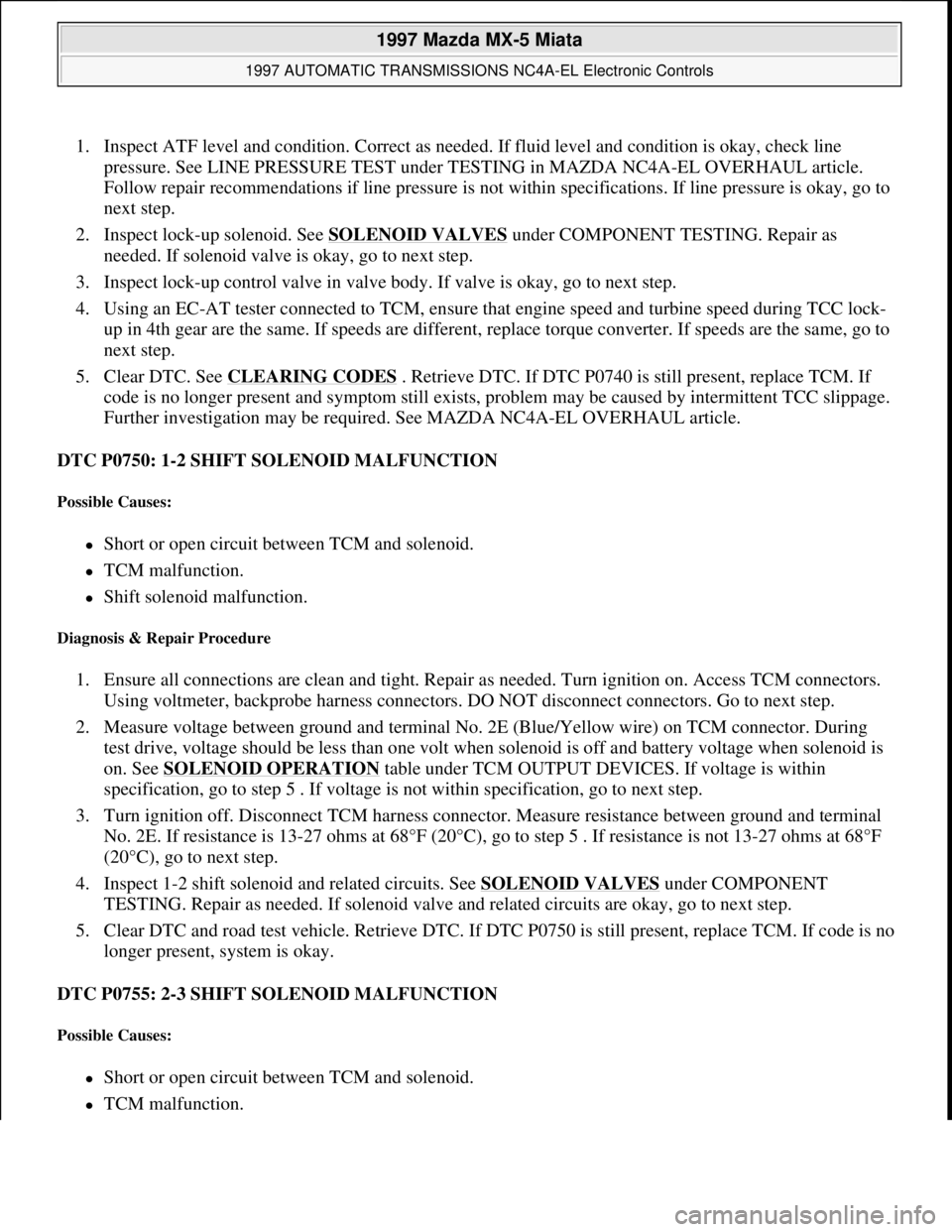
1. Inspect ATF level and condition. Correct as needed. If fluid level and condition is okay, check line
pressure. See LINE PRESSURE TEST under TESTING in MAZDA NC4A-EL OVERHAUL article.
Follow repair recommendations if line pressure is not within specifications. If line pressure is okay, go to
next step.
2. Inspect lock-up solenoid. See SOLENOID VALVES
under COMPONENT TESTING. Repair as
needed. If solenoid valve is okay, go to next step.
3. Inspect lock-up control valve in valve body. If valve is okay, go to next step.
4. Using an EC-AT tester connected to TCM, ensure that engine speed and turbine speed during TCC lock-
up in 4th gear are the same. If speeds are different, replace torque converter. If speeds are the same, go to
next step.
5. Clear DTC. See CLEARING CODES
. Retrieve DTC. If DTC P0740 is still present, replace TCM. If
code is no longer present and symptom still exists, problem may be caused by intermittent TCC slippage.
Further investigation may be required. See MAZDA NC4A-EL OVERHAUL article.
DTC P0750: 1-2 SHIFT SOLENOID MALFUNCTION
Possible Causes:
Short or open circuit between TCM and solenoid.
TCM malfunction.
Shift solenoid malfunction.
Diagnosis & Repair Procedure
1. Ensure all connections are clean and tight. Repair as needed. Turn ignition on. Access TCM connectors.
Using voltmeter, backprobe harness connectors. DO NOT disconnect connectors. Go to next step.
2. Measure voltage between ground and terminal No. 2E (Blue/Yellow wire) on TCM connector. During
test drive, voltage should be less than one volt when solenoid is off and battery voltage when solenoid is
on. See SOLENOID OPERATION
table under TCM OUTPUT DEVICES. If voltage is within
specification, go to step 5 . If voltage is not within specification, go to next step.
3. Turn ignition off. Disconnect TCM harness connector. Measure resistance between ground and terminal
No. 2E. If resistance is 13-27 ohms at 68°F (20°C), go to step 5 . If resistance is not 13-27 ohms at 68°F
(20°C), go to next step.
4. Inspect 1-2 shift solenoid and related circuits. See SOLENOID VALVES
under COMPONENT
TESTING. Repair as needed. If solenoid valve and related circuits are okay, go to next step.
5. Clear DTC and road test vehicle. Retrieve DTC. If DTC P0750 is still present, replace TCM. If code is no
longer present, system is okay.
DTC P0755: 2-3 SHIFT SOLENOID MALFUNCTION
Possible Causes:
Short or open circuit between TCM and solenoid.
TCM malfunction.
1997 Mazda MX-5 Miata
1997 AUTOMATIC TRANSMISSIONS NC4A-EL Electronic Controls
Microsoft
Sunday, July 05, 2009 1:35:04 PMPage 16 © 2005 Mitchell Repair Information Company, LLC.
Page 66 of 514

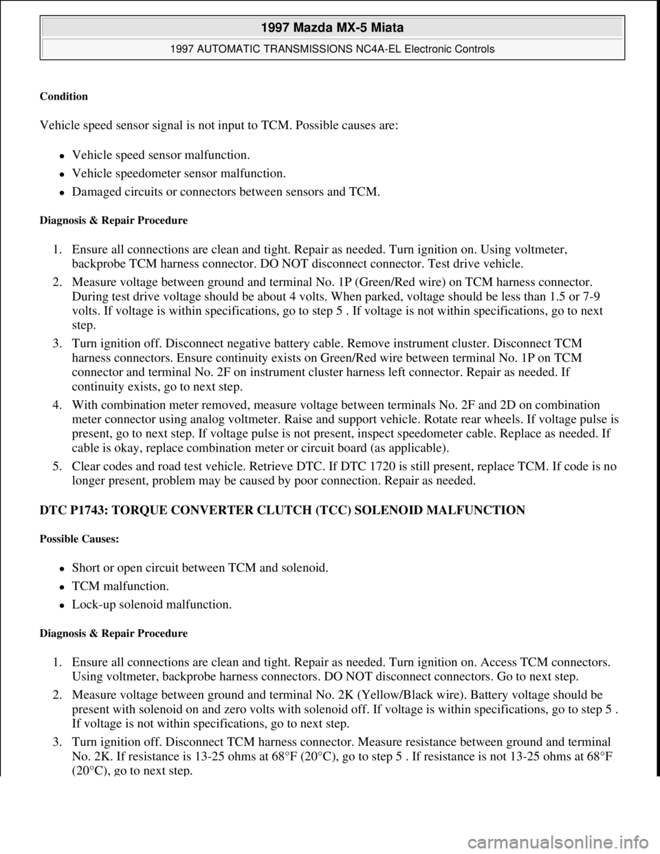
Condition
Vehicle speed sensor signal is not input to TCM. Possible causes are:
Vehicle speed sensor malfunction.
Vehicle speedometer sensor malfunction.
Damaged circuits or connectors between sensors and TCM.
Diagnosis & Repair Procedure
1. Ensure all connections are clean and tight. Repair as needed. Turn ignition on. Using voltmeter,
backprobe TCM harness connector. DO NOT disconnect connector. Test drive vehicle.
2. Measure voltage between ground and terminal No. 1P (Green/Red wire) on TCM harness connector.
During test drive voltage should be about 4 volts. When parked, voltage should be less than 1.5 or 7-9
volts. If voltage is within specifications, go to step 5 . If voltage is not within specifications, go to next
step.
3. Turn ignition off. Disconnect negative battery cable. Remove instrument cluster. Disconnect TCM
harness connectors. Ensure continuity exists on Green/Red wire between terminal No. 1P on TCM
connector and terminal No. 2F on instrument cluster harness left connector. Repair as needed. If
continuity exists, go to next step.
4. With combination meter removed, measure voltage between terminals No. 2F and 2D on combination
meter connector using analog voltmeter. Raise and support vehicle. Rotate rear wheels. If voltage pulse is
present, go to next step. If voltage pulse is not present, inspect speedometer cable. Replace as needed. If
cable is okay, replace combination meter or circuit board (as applicable).
5. Clear codes and road test vehicle. Retrieve DTC. If DTC 1720 is still present, replace TCM. If code is no
longer present, problem may be caused by poor connection. Repair as needed.
DTC P1743: TORQUE CONVERTER CLUTCH (TCC) SOLENOID MALFUNCTION
Possible Causes:
Short or open circuit between TCM and solenoid.
TCM malfunction.
Lock-up solenoid malfunction.
Diagnosis & Repair Procedure
1. Ensure all connections are clean and tight. Repair as needed. Turn ignition on. Access TCM connectors.
Using voltmeter, backprobe harness connectors. DO NOT disconnect connectors. Go to next step.
2. Measure voltage between ground and terminal No. 2K (Yellow/Black wire). Battery voltage should be
present with solenoid on and zero volts with solenoid off. If voltage is within specifications, go to step 5 .
If voltage is not within specifications, go to next step.
3. Turn ignition off. Disconnect TCM harness connector. Measure resistance between ground and terminal
No. 2K. If resistance is 13-25 ohms at 68°F (20°C), go to step 5 . If resistance is not 13-25 ohms at 68°F
(20°C),
go to next step.
1997 Mazda MX-5 Miata
1997 AUTOMATIC TRANSMISSIONS NC4A-EL Electronic Controls
Microsoft
Sunday, July 05, 2009 1:35:04 PMPage 18 © 2005 Mitchell Repair Information Company, LLC.
Page 67 of 514

4. Inspect lock-up solenoid and related circuits. See SOLENOID VALVES under COMPONENT
TESTING. Repair as needed. If solenoid valve and related circuits are okay, go to next step.
5. Clear codes and road test vehicle. Retrieve DTC. If DTC P1743 is still present, replace TCM. If code is
no longer present, problem may be caused by poor connection. Repair as needed.
DTC P1765: 3-2 CONTROL SOLENOID VALVE MALFUNCTION
Possible Causes:
Short or open circuit between TCM and solenoid.
TCM malfunction.
3-2 control solenoid malfunction.
Diagnosis & Repair Procedure
1. Ensure all connections are clean and tight. Repair as needed. Turn ignition on. Access TCM connectors.
Using voltmeter, backprobe harness connectors. DO NOT disconnect connectors. Go to next step.
2. Drive vehicle and measure voltage between ground and terminal No. 2M (Blue/Orange wire). Battery
voltage should be present with solenoid on during 3-2 or 4-3 downshift, and zero volts with solenoid off.
If voltage is within specifications, go to step 5 . If voltage is not within specifications, go to next step.
3. Turn ignition off. Disconnect TCM harness connector. Measure resistance between ground and terminal
No. 2M. If resistance is 13-27 ohms at 68°F (20°C), go to step 5 . If resistance is not 13-27 ohms at 68°F
(20°C), go to next step.
4. Inspect 3-2 control clutch solenoid and related circuits. See SOLENOID VALVES
under
COMPONENT TESTING. Repair as needed. If solenoid valve and related circuits are okay, go to next
step.
5. Clear codes and road test vehicle. Retrieve DTC. If DTC P1765 is still present, replace TCM. If code is
no longer present, problem may be caused by poor connection. Repair as needed.
DTC P1790: THROTTLE POSITION (TP) SENSOR MALFUNCTION
Condition
TP sensor voltage is less than one volt or more than 4.9 volts. Possible causes are:
Poor harness connection at TP sensor.
Circuit fault between TP sensor and ECM or TCM.
TP sensor malfunction.
ECM or TCM malfunction.
Diagnosis & Repair Procedure
NOTE: If DTC P0725 is also present, repair it first and then proceed with this test.
1997 Mazda MX-5 Miata
1997 AUTOMATIC TRANSMISSIONS NC4A-EL Electronic Controls
Microsoft
Sunday, July 05, 2009 1:35:04 PMPage 19 © 2005 Mitchell Repair Information Company, LLC.
Page 79 of 514

1997-2001 DRIVE AXLES
Axle Shafts - MX-5 Miata
TROUBLE SHOOTING
Inspect CV joint boot on axle shaft for cracks, damage, leaking, grease, and looseness in boot band. Inspect axle
shaft for bending, cracks, and wear of joint splines. Repair or replace as necessary.
REMOVAL & INSTALLATION
AXLE SHAFTS
Removal
1. Raise vehicle and support with safety stands. Remove wheel and tire assembly. Remove axle shaft lock
nut. See Fig. 1
.
2. Remove brake caliper assembly. Remove lower control arm bolt at knuckle, and pull knuckle/hub
assembly outward. Using pry bar between differential housing and inner CV joint, remove inner CV joint
from differential. See Fig. 2
. Remove axle shaft from knuckle/hub assembly. NOTE: See DRIVE AXLE NOISE DIAGNOSIS article in GENERAL INFORMATION.
CAUTION: If vehicle is equipped with ABS, before performing following procedure,
remove ABS wheel speed sensor (axle side) and fix it to an appropriate
place where sensor will not be pulled by mistake while servicing vehicle.
NOTE: If axle shaft will not come out of rear hub support easily, install a discarded nut
onto axle shaft so that nut is flush with end of axle shaft. Tap nut with a copper
hammer to loosen axle shaft from wheel hub.
1997 Mazda MX-5 Miata
1997-2001 DRIVE AXLES Axle Shafts - MX-5 Miata
1997 Mazda MX-5 Miata
1997-2001 DRIVE AXLES Axle Shafts - MX-5 Miata
Microsoft
Sunday, July 05, 2009 1:51:37 PMPage 1 © 2005 Mitchell Repair Information Company, LLC.
Microsoft
Sunday, July 05, 2009 1:51:53 PMPage 1 © 2005 Mitchell Repair Information Company, LLC.