1997 MAZDA MIATA engine oil
[x] Cancel search: engine oilPage 245 of 514
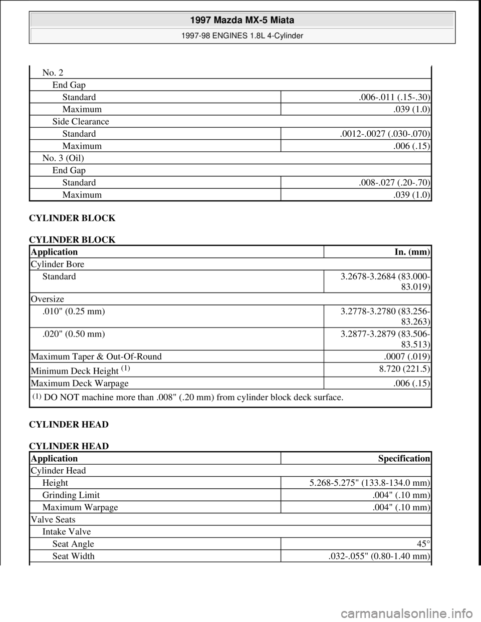
CYLINDER BLOCK
CYLINDER BLOCK
CYLINDER HEAD
CYLINDER HEAD
No. 2
End Gap
Standard.006-.011 (.15-.30)
Maximum.039 (1.0)
Side Clearance
Standard.0012-.0027 (.030-.070)
Maximum.006 (.15)
No. 3 (Oil)
End Gap
Standard.008-.027 (.20-.70)
Maximum.039 (1.0)
ApplicationIn. (mm)
Cylinder Bore
Standard3.2678-3.2684 (83.000-
83.019)
Oversize
.010" (0.25 mm)3.2778-3.2780 (83.256-
83.263)
.020" (0.50 mm)3.2877-3.2879 (83.506-
83.513)
Maximum Taper & Out-Of-Round.0007 (.019)
Minimum Deck Height (1) 8.720 (221.5)
Maximum Deck Warpage.006 (.15)
(1)DO NOT machine more than .008" (.20 mm) from cylinder block deck surface.
ApplicationSpecification
Cylinder Head
Height5.268-5.275" (133.8-134.0 mm)
Grinding Limit.004" (.10 mm)
Maximum Warpage.004" (.10 mm)
Valve Seats
Intake Valve
Seat Angle45°
Seat Width.032-.055" (0.80-1.40 mm)
1997 Mazda MX-5 Miata
1997-98 ENGINES 1.8L 4-Cylinder
Microsoft
Sunday, July 05, 2009 1:55:15 PMPage 39 © 2005 Mitchell Repair Information Company, LLC.
Page 246 of 514
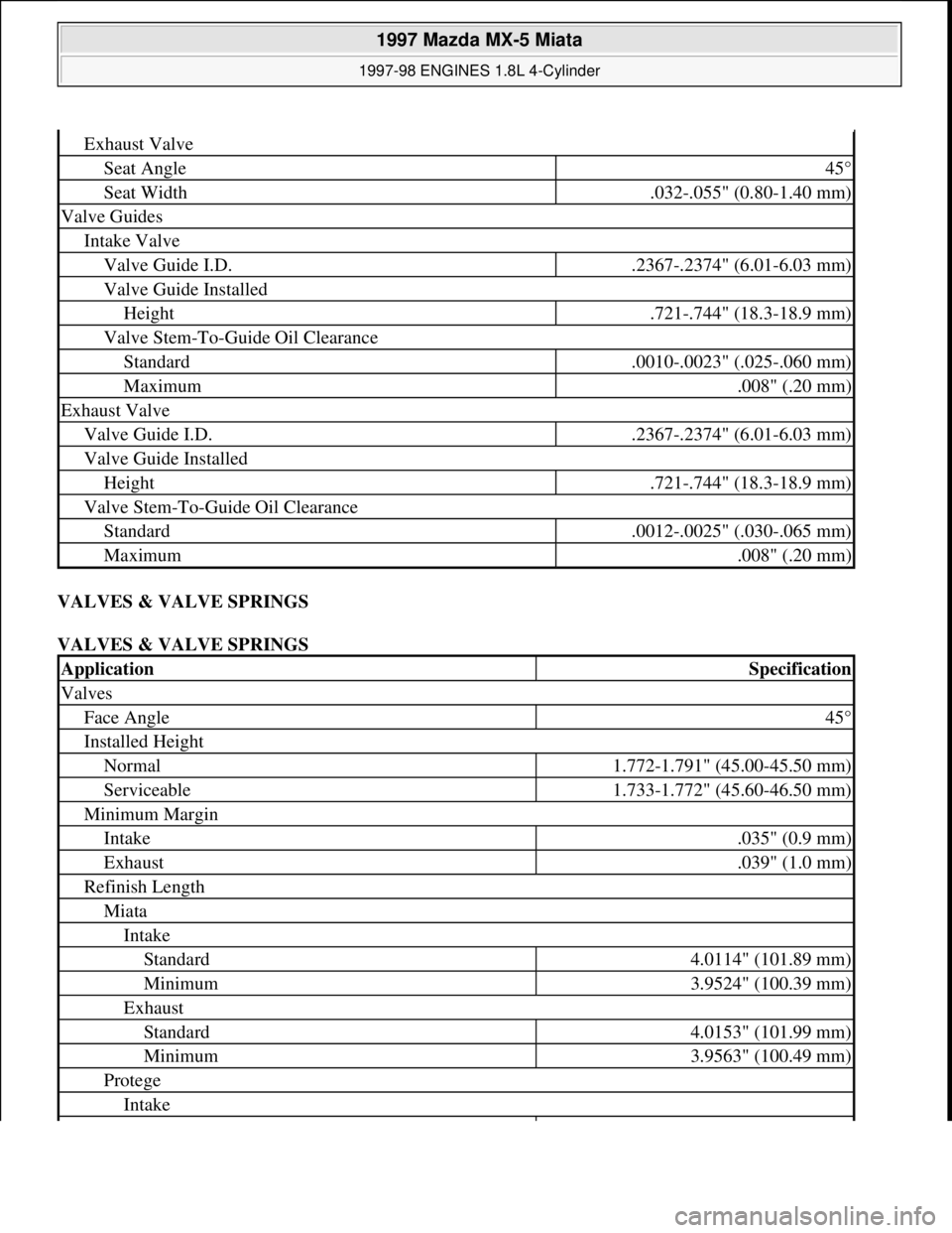
VALVES & VALVE SPRINGS
VALVES & VALVE SPRINGS
Exhaust Valve
Seat Angle45°
Seat Width.032-.055" (0.80-1.40 mm)
Valve Guides
Intake Valve
Valve Guide I.D..2367-.2374" (6.01-6.03 mm)
Valve Guide Installed
Height.721-.744" (18.3-18.9 mm)
Valve Stem-To-Guide Oil Clearance
Standard.0010-.0023" (.025-.060 mm)
Maximum.008" (.20 mm)
Exhaust Valve
Valve Guide I.D..2367-.2374" (6.01-6.03 mm)
Valve Guide Installed
Height.721-.744" (18.3-18.9 mm)
Valve Stem-To-Guide Oil Clearance
Standard.0012-.0025" (.030-.065 mm)
Maximum.008" (.20 mm)
ApplicationSpecification
Valves
Face Angle45°
Installed Height
Normal1.772-1.791" (45.00-45.50 mm)
Serviceable1.733-1.772" (45.60-46.50 mm)
Minimum Margin
Intake.035" (0.9 mm)
Exhaust.039" (1.0 mm)
Refinish Length
Miata
Intake
Standard4.0114" (101.89 mm)
Minimum3.9524" (100.39 mm)
Exhaust
Standard4.0153" (101.99 mm)
Minimum3.9563" (100.49 mm)
Protege
Intake
1997 Mazda MX-5 Miata
1997-98 ENGINES 1.8L 4-Cylinder
Microsoft
Sunday, July 05, 2009 1:55:15 PMPage 40 © 2005 Mitchell Repair Information Company, LLC.
Page 247 of 514
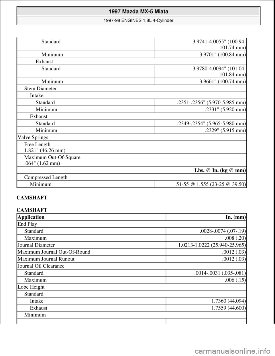
CAMSHAFT
CAMSHAFT
Standard3.9741-4.0055" (100.94-
101.74 mm)
Minimum3.9701" (100.84 mm)
Exhaust
Standard3.9780-4.0094" (101.04-
101.84 mm)
Minimum3.9661" (100.74 mm)
Stem Diameter
Intake
Standard.2351-.2356" (5.970-5.985 mm)
Minimum.2331" (5.920 mm)
Exhaust
Standard.2349-.2354" (5.965-5.980 mm)
Minimum.2329" (5.915 mm)
Valve Springs
Free Length
1.821" (46.26 mm)
Maximum Out-Of-Square
.064" (1.62 mm)
Lbs. @ In. (kg @ mm)
Compressed Length
Minimum51-55 @ 1.555 (23-25 @ 39.50)
ApplicationIn. (mm)
End Play
Standard.0028-.0074 (.07-.19)
Maximum.008 (.20)
Journal Diameter1.0213-1.0222 (25.940-25.965)
Maximum Journal Out-Of-Round.0012 (.03)
Maximum Journal Runout.0012 (.03)
Journal Oil Clearance
Standard.0014-.0031 (.035-.081)
Maximum.006 (.15)
Lobe Height
Standard
Intake1.7360 (44.094)
Exhaust1.7559 (44.600)
Minimum
1997 Mazda MX-5 Miata
1997-98 ENGINES 1.8L 4-Cylinder
Microsoft
Sunday, July 05, 2009 1:55:15 PMPage 41 © 2005 Mitchell Repair Information Company, LLC.
Page 248 of 514
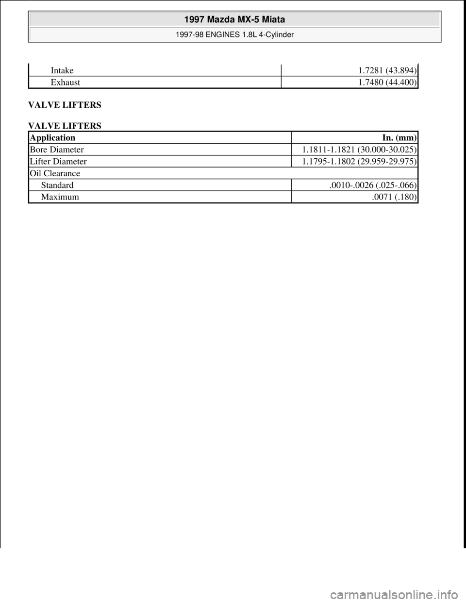
VALVE LIFTERS
VALVE LIFTERS
Intake1.7281 (43.894)
Exhaust1.7480 (44.400)
ApplicationIn. (mm)
Bore Diameter1.1811-1.1821 (30.000-30.025)
Lifter Diameter1.1795-1.1802 (29.959-29.975)
Oil Clearance
Standard.0010-.0026 (.025-.066)
Maximum.0071 (.180)
1997 Mazda MX-5 Miata
1997-98 ENGINES 1.8L 4-Cylinder
Microsoft
Sunday, July 05, 2009 1:55:15 PMPage 42 © 2005 Mitchell Repair Information Company, LLC.
Page 290 of 514

Check for damage, excessive wear and signs of bearing seizure. Inspect steering knuckle and hub for cracks,
scoring and rust. Check for damaged dust cover and poor fit with steering knuckle. Replace components as
necessary.
Installation
To install, reverse removal procedure. Adjust wheel bearing preload. See WHEEL BEARING
ADJUSTMENT under ADJUSTMENTS. Stake axle nut.
LOWER CONTROL ARM & BALL JOINT
Removal
1. Raise and support vehicle. Remove wheel assembly. Remove engine splash shield (if equipped). Separate
tie rod end from steering knuckle (as necessary). Remove stabilizer bar from lower control arm.
2. Remove shock lower mounting bolt and separate lower shock from lower control arm. Remove lower
control arm ball joint cotter pin and nut. Separate lower control arm ball joint stud from knuckle using
Puller (49 T028 3A0). Remove lower control arm pivot bolts and remove lower control arm.
Inspection
Check lower control arm for damage or cracks. Check bushings for deterioration and excessive wear. Check
ball joint for excessive wear. Examine dust boot for damage. Replace components as necessary.
Bushing Replacement
Cut or press old bushing from control arm. Coat NEW bushing with paraffin-based oil. Press new bushing into
control arm.
Installation (All Models)
To install, reverse removal procedure. Tighten lower control arm-to-frame bolts to specification with vehicle
resting on ground and suspension unloaded. See TORQUE SPECIFICATIONS
.
UPPER CONTROL ARM & BALL JOINT
Removal
Raise and support vehicle. Remove wheel assembly. Remove engine splash shield. Remove wheel speed sensor
harness band. Remove shock lower mounting bolt, and separate lower shock from lower control arm. Remove
upper control arm ball joint cotter pin and nut. Separate upper control arm ball joint stud from knuckle using
Puller (49-0118-850C). Remove upper control arm pivot bolts and remove upper control arm.
Inspection
Check upper control arm for damage or cracks. Check bushings for deterioration and excessive wear. Check
ball joint for excessive wear. Examine dust boot for damage. Replace components as necessary.
1997 Mazda MX-5 Miata
1997-2000 SUSPENSION Front - Miata
Microsoft
Sunday, July 05, 2009 1:38:08 PMPage 3 © 2005 Mitchell Repair Information Company, LLC.
Page 291 of 514

Bushing Replacement
Cut or press old bushing from control arm. Coat new bushing with paraffin-based oil. Press new bushing into
control arm.
Installation (All Models)
To install, reverse removal procedure. Tighten upper control arm pivot bolts to specification with vehicle
resting on ground and suspension unloaded. See TORQUE SPECIFICATIONS
.
SHOCK ASSEMBLY
Removal (1997)
Raise and support vehicle. Remove wheel assembly. Remove engine splash shield. Remove wheel speed sensor
harness band. Remove stabilizer link bolt. Remove upper control arm ball joint cotter pin and nut. Separate
upper control arm ball joint stud from knuckle using Puller (49-0118-850C). Loosen lower control arm pivot
bolts. Remove shock upper mount nuts and lower bolt. Move lower control arm just enough to remove shock
assembly. DO NOT damage brake line.
Removal (1999 & 2000)
Raise and support vehicle. Remove wheel assembly. Remove engine splash shield. Remove wheel speed sensor.
Remove stabilizer link bolt. Separate lower control arm ball joint stud from knuckle using Puller (49-T028-
3A0). Loosen lower control arm pivot bolts. Inside engine compartment, on 1999 models, remove strut bar. See
FRONT STRUT BAR (1999)
. On 2000 models, remove shock upper mount nuts. On all models, under car,
remove lower bolt. Move lower control arm just enough to remove shock assembly. DO NOT damage brake
line.
Disassembly
Clamp upper shock mount in vise. Loosen piston lock nut 2 turns only. Compress coil spring using coil spring
compressor. Remove piston lock nut. Slowly release compressor tension. Remove components. Remove coil
spring. Remove shock from vise.
Inspection
Check shock tube for damage, oil leakage and abnormal noise. Check rubber components for deterioration or
damage. Inspect coil spring for signs of fatigue or damage. Replace components as necessary.
Reassembly (1997)
Clamp shock in vise. Install coil spring and components in reverse order of disassembly. Ensure coil spring is
well seated in upper and lower spring seats. See Fig. 2
. Tighten piston rod nut. See TORQUE
SPECIFICATIONS .
1997 Mazda MX-5 Miata
1997-2000 SUSPENSION Front - Miata
Microsoft
Sunday, July 05, 2009 1:38:08 PMPage 4 © 2005 Mitchell Repair Information Company, LLC.
Page 316 of 514
COMPRESSOR
Removal & Installation
1. Before disconnecting negative battery cable, obtain radio anti-theft code from vehicle owner. Disconnect
negative battery cable.
2. Raise and support front of vehicle with safety stands. Discharge A/C system using approved refrigerant
recovery/recycling equipment. Remove splash shield and air guide.
3. Disconnect compressor clutch connector. Disconnect refrigerant lines from compressor, and plug open
fittings. Remove compressor drive belt. Remove compressor bolts and compressor. To install, reverse
removal procedure. Adjust drive belt deflection. Apply clean compressor oil to "O" ring before
connecting fittings. DO NOT apply compressor oil to fitting nuts. Evacuate and charge A/C system.
Check for leaks.
CONDENSER & RECEIVER-DRIER
Removal
Raise and support front of vehicle with safety stands. Discharge A/C system using approved refrigerant
recovery/recycling equipment. Remove splash shield and air guide. Remove condenser. Remove receiver-drier.
Plug open fittings.
Installation
To install, reverse removal procedure. Apply clean compressor oil to "O" rings before connecting fittings. DO
NOT apply compressor oil to fitting nuts. If installing new condenser, add 1.0 ounce of compressor oil to A/C
compressor. If installing new receiver-drier, add .3 ounce of compressor oil to A/C compressor. Evacuate and
charge A/C system. Check for leaks.
EVAPORATOR UNIT
Removal
1. Discharge A/C system using approved refrigerant recovery/recycling equipment. Disconnect refrigerant
pipes from evaporator tubes at engine compartment firewall and plug open fittings. Remove passenger-
side instrument panel undercover. Remove glove box.
2. Disconnect electrical connectors. Loosen seal plates between evaporator unit, heater unit and blower unit.
Remove evaporator unit. Disassemble evaporator unit to remove evaporator core and thermo-switch. See WARNING:To avoid injury from accidental air bag deployment, read and follow all
SERVICE PRECAUTIONS and DISABLING & ACTIVATING AIR BAG
SYSTEM procedures in AIR BAG RESTRAINT SYSTEM article in the
ACCESSORIES/SAFETY EQUIPMENT section.
NOTE: For removal and installation procedures not covered in this article, see HEATER
SYSTEM article.
1997 Mazda MX-5 Miata
A/C-HEATER SYSTEM - MANUAL 1997 Manual A/C-Heater System
Microsoft
Sunday, July 05, 2009 1:41:48 PMPage 7 © 2005 Mitchell Repair Information Company, LLC.
Page 323 of 514
Cracks Or Tears In Belt Surface
Missing, Damaged, Cracked Or Rounded Teeth
Oil Contamination
Damaged Or Faulty Tensioners
Incorrect Tension Adjustment
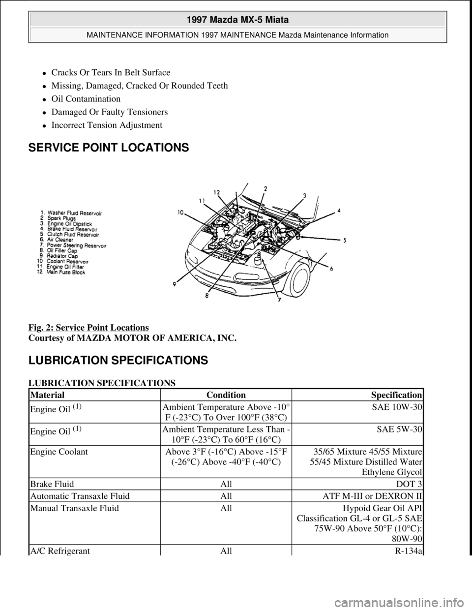
SERVICE POINT LOCATIONS
Fig. 2: Service Point Locations
Courtesy of MAZDA MOTOR OF AMERICA, INC.
LUBRICATION SPECIFICATIONS
LUBRICATION SPECIFICATIONS
MaterialConditionSpecification
Engine Oil (1) Ambient Temperature Above -10°
F (-23°C) To Over 100°F (38°C)SAE 10W-30
Engine Oil (1) Ambient Temperature Less Than -
10°F (-23°C) To 60°F (16°C)SAE 5W-30
Engine CoolantAbove 3°F (-16°C) Above -15°F
(-26°C) Above -40°F (-40°C)35/65 Mixture 45/55 Mixture
55/45 Mixture Distilled Water
Ethylene Glycol
Brake FluidAllDOT 3
Automatic Transaxle FluidAllATF M-III or DEXRON II
Manual Transaxle FluidAllHypoid Gear Oil API
Classification GL-4 or GL-5 SAE
75W-90 Above 50°F (10°C):
80W-90
A/C RefrigerantAllR-134a
1997 Mazda MX-5 Miata
MAINTENANCE INFORMATION 1997 MAINTENANCE Mazda Maintenance Information
Microsoft
Sunday, July 05, 2009 1:41:19 PMPage 3 © 2005 Mitchell Repair Information Company, LLC.