1997 MAZDA MIATA engine oil
[x] Cancel search: engine oilPage 218 of 514
wheel puller. Pry out seal.
Installation
1. Apply light oil coat to seal lip. Using a hammer and seal installer, tap seal into oil pump body until it is
flush with edge of pump body. DO NOT bottom seal in pump body. Align keyway slots, and install
crankshaft sprocket and Woodruff key with tapered side toward oil pump body. Install crankshaft
sprocket bolt.
2. Using Crankshaft Lock Tool (49-D011-102), lock crankshaft sprocket into position. Tighten lock bolt to
specification. See TORQUE SPECIFICATIONS
.
3. Install timing belt. See TIMING BELT
under REMOVAL & INSTALLATION. Install timing belt
covers, pulleys and drive belts. Reconnect negative battery cable and ensure timing is correct.
TIMING BELT
Removal (Miata)
1. Disconnect negative battery cable. Drain cooling system. Remove radiator hose and by-pass hoses from
thermostat housing. Remove air cleaner intake duct assembly from between throttle body and air cleaner
filter housing.
2. Remove drive belts and water pump pulley. Align crankshaft pulley timing mark with cylinder No. 1 at
TDC of compression stroke. Hold crankshaft pulley stationary. Remove crankshaft pulley bolts and
pulley. Remove crankshaft pulley hub bolt and hub.
3. Remove cylinder head cover. Remove upper, center and lower timing belt cover. If timing belt is to be
reused, mark timing belt rotation direction. Ensure timing marks on camshaft sprockets are aligned. See
Fig. 8
. Loosen timing belt tensioner lock bolt, and move tensioner away from belt with spring fully
expanded. Remove timing belt.
Removal (Protege)
1. Disconnect negative battery cable. Raise and support vehicle. Remove right front wheel. Remove right
side cover and undercover.
2. Remove drive belts and water pump pulley. Align crankshaft pulley timing mark with cylinder No. 1 at
TDC of compression stroke. Hold crankshaft stationary. Remove crankshaft pulley bolts and pulley.
Remove crankshaft pulley hub bolt and hub.
3. Remove cylinder head cover. Remove upper, center and lower timing belt cover. If timing belt is to be
reused, mark timing belt rotation direction. Ensure timing marks on camshaft sprockets are aligned. See
Fig. 8
. Loosen timing belt tensioner lock bolt, and move tensioner away from belt with spring fully
expanded. Remove timin
g belt. NOTE: For 1997-98 vehicles, the manufacturer recommends the belt be replaced at
60,000 mile intervals for vehicles sold outside of California and Massachusetts.
For vehicles sold in California and Massachusetts, inspect timing belt at 60,000
and 90,000 miles, and replace timing belt at 105,000 miles.
1997 Mazda MX-5 Miata
1997-98 ENGINES 1.8L 4-Cylinder
Microsoft
Sunday, July 05, 2009 1:55:15 PMPage 12 © 2005 Mitchell Repair Information Company, LLC.
Page 219 of 514
Inspection (All Models)
Check timing belt for cracks, peeling, abrasion or other damage. Check tensioner bearing for looseness or
roughness of rotation. Inspect tensioner spring for stretching. Replace parts as necessary.
Installation (All Models)
1. Position notch on crankshaft sprocket to 12 o'clock position (aligned with mark on oil pump). Align
timing marks on camshaft sprockets. See Fig. 8
. Ensure crankshaft timing mark is at TDC. Install belt
around crankshaft sprocket, then working in a counterclockwise direction, route belt around camshaft
sprockets.
2. Loosen timing belt tensioner lock bolt and allow spring to apply tension on belt. Snug tensioner lock bolt.
Rotate crankshaft 2 complete turns in direction of normal engine rotation. Ensure timing marks align. If
timing marks are not aligned, remove belt, realign all timing marks, and repeat installation procedure.
3. Check timing belt deflection with 22 lbs. (10 kg) of pressure applied to belt. See Fig. 9
. Ensure timing
belt deflection is within specification. See TIMING BELT DEFLECTION
.
TIMING BELT DEFLECTION
Application(1) Deflection In. (mm)
Miata & Protege.35-.45 (9.0-11.5)
(1)Deflection measurement is with 22 lbs. (10 kg) of pressure applied to timing belt. See Fig. 9 .
1997 Mazda MX-5 Miata
1997-98 ENGINES 1.8L 4-Cylinder
Microsoft
Sunday, July 05, 2009 1:55:15 PMPage 13 © 2005 Mitchell Repair Information Company, LLC.
Page 226 of 514
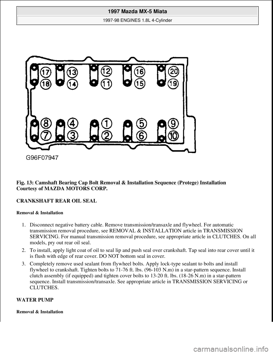
Fig. 13: Camshaft Bearing Cap Bolt Removal & Installation Sequence (Protege) Installation
Courtesy of MAZDA MOTORS CORP.
CRANKSHAFT REAR OIL SEAL
Removal & Installation
1. Disconnect negative battery cable. Remove transmission/transaxle and flywheel. For automatic
transmission removal procedure, see REMOVAL & INSTALLATION article in TRANSMISSION
SERVICING. For manual transmission removal procedure, see appropriate article in CLUTCHES. On all
models, pry out rear oil seal.
2. To install, apply light coat of oil to seal lip and push seal over crankshaft. Tap seal into rear cover until it
is flush with edge of rear cover. DO NOT bottom seal in cover.
3. Completely remove used sealant from flywheel bolts. Apply lock-type sealant to bolts and install
flywheel to crankshaft. Tighten bolts to 71-76 ft. lbs. (96-103 N.m) in a star-pattern sequence. Install
clutch assembly (if equipped) and tighten cover bolts to 13-20 ft. lbs. (18-26 N.m) in a star-pattern
sequence. Install transmission/transaxle. See appropriate article in TRANSMISSION SERVICING or
CLUTCHES.
WATER PUMP
Removal & Installation
1997 Mazda MX-5 Miata
1997-98 ENGINES 1.8L 4-Cylinder
Microsoft
Sunday, July 05, 2009 1:55:15 PMPage 20 © 2005 Mitchell Repair Information Company, LLC.
Page 227 of 514
1. Drain engine coolant. Disconnect battery cable. Position No. 1 cylinder at TDC of compression stroke.
On Protege, remove right side cover and undercover.
2. On Miata, remove air cleaner intake duct from between throttle body and air cleaner/filter assembly. On
all models, remove upper radiator hose and by-pass hoses from thermostat housing.
3. Remove drive belts and water pump pulley. Remove power steering pump with hoses attached and secure
pump away from engine (if necessary). Remove timing belt, tensioner and idler. See TIMING BELT.
4. Unbolt water inlet pipe from water pump. Water pump inlet pipe has lower radiator hose and by-pass pipe
attached to it. Remove bolts from water pump. To install, reverse removal procedure. Tighten bolt to
specification. See TORQUE SPECIFICATIONS
.
OIL PAN
Removal & Installation (Miata)
1. Disconnect negative battery cable. Drain engine oil. Remove dipstick, tube and "O" ring. Raise vehicle on
hoist. Remove engine undercover. Disconnect steering column shaft at steering rack coupling. See Fig.
14 . Remove engine mount nuts. Lift and support engine using jack.
2. Support crossmember using transmission jack and remove crossmember bolts. Slowly and carefully lower
crossmember until clearance between oil pan and steering rack is about 4 inches. Remove oil pan bolts
from engine block and transmission.
3. DO NOT damage sealant contact surfaces. Remove oil pan by prying between oil pan and transmission
support. Remove oil pan baffle by prying it from engine. See Fig. 14
. DO NOT deform oil pan baffle.
Replace oil pan baffle if deformed. Clean sealant from oil pan, bolts, engine block and both sides of oil
pan baffle.
4. To install, apply oil resistant sealant to engine block and oil pan. Install oil pan baffle and oil pan within 5
minutes of applying sealant. To complete installation, reverse removal procedure. Tighten bolts to
specification. See TORQUE SPECIFICATIONS
. Fill engine with oil to specification. See ENGINE
LUBRICATION SYSTEM under ENGINE OILING. NOTE: For further information on cooling systems, see SPECIFICATIONS & ELECTRIC
COOLING FANS article in ENGINE COOLING.
NOTE: On Miata, engine must be supported in order to remove oil pan.
1997 Mazda MX-5 Miata
1997-98 ENGINES 1.8L 4-Cylinder
Microsoft
Sunday, July 05, 2009 1:55:15 PMPage 21 © 2005 Mitchell Repair Information Company, LLC.
Page 228 of 514
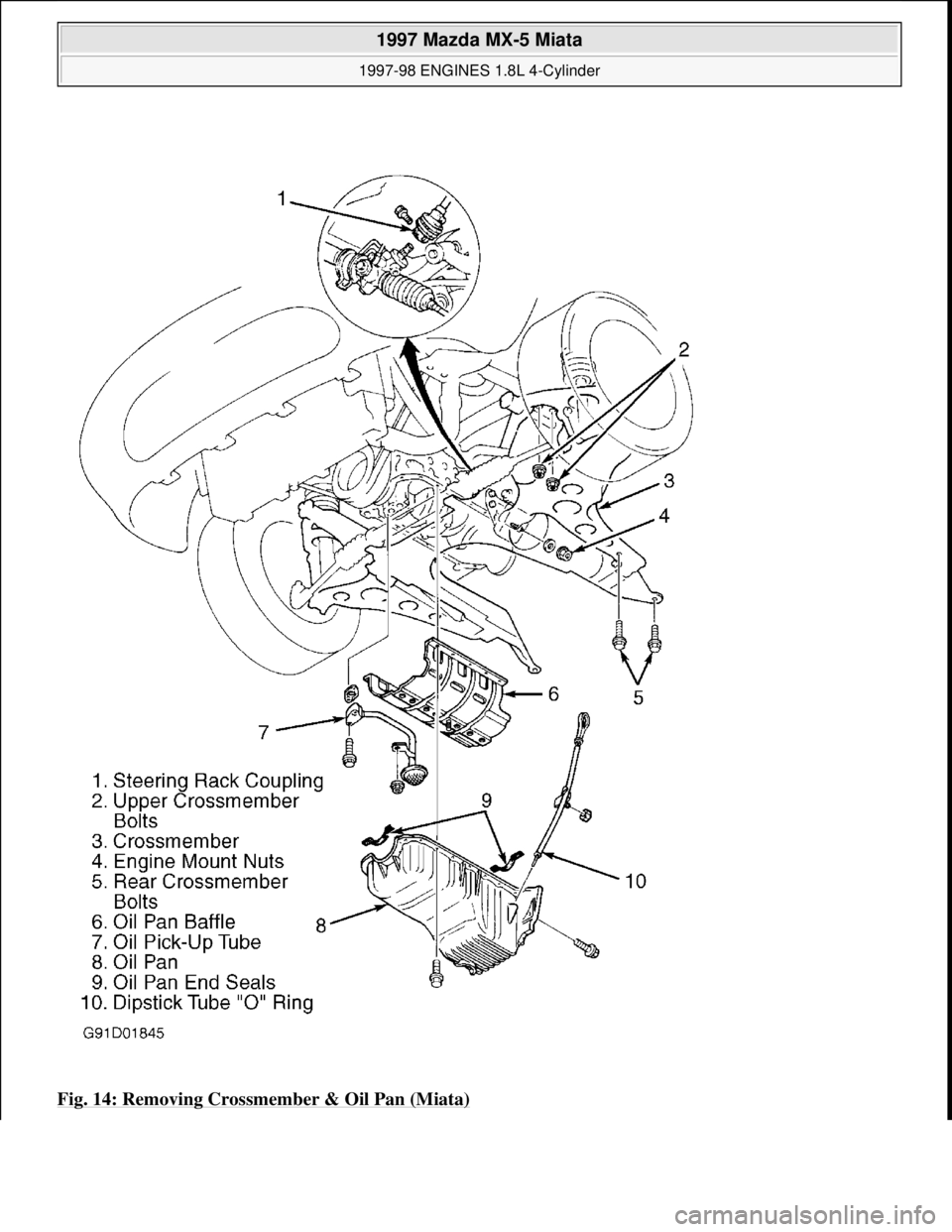
Fig. 14: Removing Crossmember & Oil Pan (Miata)
1997 Mazda MX-5 Miata
1997-98 ENGINES 1.8L 4-Cylinder
Microsoft
Sunday, July 05, 2009 1:55:15 PMPage 22 © 2005 Mitchell Repair Information Company, LLC.
Page 229 of 514

Courtesy of MAZDA MOTORS CORP.
Removal & Installation (Protege)
1. Disconnect negative battery cable. Remove engine undercovers. Drain engine oil. Remove exhaust header
downpipe and brackets from front exhaust system. Remove oil pan retaining bolts.
2. DO NOT damage sealant contact surfaces. Remove oil pan by prying between oil pan and mounting
surface. On Protege, remove stiffener by prying between stiffener and cylinder block. On all models,
clean all sealant from oil pan, bolts, engine block and both sides of stiffener (Protege).
3. On Protege, apply oil resistant sealant to engine block and stiffener. Install stiffener. On all models, apply
sealant and install oil pan within 5 minutes of applying sealant. To complete installation, reverse removal
procedure. Tighten all bolts to specification. See TORQUE SPECIFICATIONS
. Fill engine with oil to
specification. See ENGINE LUBRICATION SYSTEM
under ENGINE OILING.
OVERHAUL
CYLINDER HEAD
Cylinder Head
Clean carbon and gasket material from all mating surfaces. Using a tap, clean cylinder head threads. Check
cylinder head warpage. If warpage exceeds specification, resurface head, but DO NOT exceed grinding limit.
See CYLINDER HEAD
under ENGINE SPECIFICATIONS. After resurfacing cylinder head, check cylinder
head height. Replace cylinder head if height is less than minimum specification.
Valve Springs
Ensure valve spring free length, out-of-square and compressed length are within specification. See VALVES &
VALVE SPRINGS under ENGINE SPECIFICATIONS. Replace valve spring if necessary.
Valve Stem Oil Seals
1. On Miata, use Installer Set (49-L012-0A0) to install valve seals. See Fig. 15 . Adjust installer dimension
"L" to seal depth of .720-.744" (18.3-18.9 mm). Using hand pressure ONLY, install seal until it contacts
cylinder head. Lightly oil valve seal lip.
2. On Protege, use Installer Set (49-L012-0A0) to install valve seals. See Fig. 15
. Adjust installer
dimension "L" to seal depth of .783" (19.9 mm). Using hand pressure, install seal until it contacts cylinder CAUTION: If reusing old oil pan bolts, remove old sealant from bolt threads.
Failure to remove old sealant may result in cracked block at bolt
holes.
NOTE: Intake and exhaust valve stem seals are different. Exhaust seals can be
identified by ridges molded into top of seal. Intake seals do not have identifying
ridges. Incorrect installation of valve stem seals will cause premature failure.
1997 Mazda MX-5 Miata
1997-98 ENGINES 1.8L 4-Cylinder
Microsoft
Sunday, July 05, 2009 1:55:15 PMPage 23 © 2005 Mitchell Repair Information Company, LLC.
Page 230 of 514

head. Lightly oil valve seal lip.
Fig. 15: Installing Valve Guide Seals
Courtesy of MAZDA MOTORS CORP.
Valve Guides
1. Check valve stem-to-valve guide oil clearance. Ensure valve guide inside diameter is within specification.
See CYLINDER HEAD
under ENGINE SPECIFICATIONS.
2. Completely disassemble cylinder head. Gradually heat cylinder head in water to 194°F (94°C). Using
Valve Guide Remover (49-B012-005), drive valve guide out, working from combustion chamber side of
cylinder head. Repeat procedure if required, keeping cylinder head hot so aluminum head will not warp.
3. If required, install new circlip on guide. Using proper components of Valve Guide Installer (49-L012-
0A0), adjust installer guide depth (dimension "L") to specification using depth micrometer or caliper. See
VALVE GUIDE INSTALLED HEIGHT
. See Fig. 16 .
4. Insert guide into pre-adjusted installer and drive guide into cylinder head from camshaft side until guide
circlip, and/or installer contact cylinder head. Measure dimension "L" (guide installed height). See Fig.
16 or Fig. 15 . If installed height is not within specification, adjust or replace valve guide or cylinder head
as necessary. See VALVE GUIDE INSTALLED HEIGHT
.
NOTE: On Miata, use only NEW exhaust valve guides to replace intake or exhaust valve
guides.
1997 Mazda MX-5 Miata
1997-98 ENGINES 1.8L 4-Cylinder
Microsoft
Sunday, July 05, 2009 1:55:15 PMPage 24 © 2005 Mitchell Repair Information Company, LLC.
Page 233 of 514

Valves
Check valve face angle, head diameter, margin thickness and stem diameter. Service or replace valves if
measurements are not within specifications. See VALVES & VALVE SPRINGS
under ENGINE
SPECIFICATIONS.
Valve Seat Correction Angles
Measure seat contact width on valve. See VALVE SEAT. If seat width is not within specification or if valve
face does not contact center of valve seat, correct seat using a 70-degree grinding stone. After correcting seat,
lightly finish seat with 45-degree grinding stone.
VALVE TRAIN
Hydraulic Lash Adjusters
1. Remove camshaft cover. Check movement of each Hydraulic Lash Adjuster (HLA) by pushing
downward using hand pressure only. If HLA compresses, replace HLA. To remove HLA, remove
camshafts. See CAMSHAFT
under REMOVAL & INSTALLATION. Mark location of HLA before
removing from bore. Lift HLA from cylinder head.
2. Inspect HLA friction surfaces for wear and damage. Replace HLA if required. Coat HLA with engine oil
and install in original location. Ensure HLA moves smoothly in bore by using small magnet attached to
HLA.
CYLINDER BLOCK ASSEMBLY
Piston & Connecting Rod Assembly
1. Before removing rod cap from crankshaft, measure and record rod side play. See CONNECTING RODS
under ENGINE SPECIFICATIONS. Before removing connecting rods, measure and record connecting
rod bearing oil clearance. See CRANKSHAFT, MAIN & CONNECTING ROD BEARINGS
under
ENGINE SPECIFICATIONS.
2. Before separating piston from connecting rod, mark piston in relation to connecting rod. Check
oscillation movement of piston and rod assembly (hold piston horizontally, lift rod and allow rod to drop
by its own weight). If pin binds in pin bore (rod does not drop), replace piston and/or pin as necessary.
3. To separate components, press piston pin out of piston and rod assembl
y, noting pressure required to
Normal1.772-1.791 (45.00-45.50)
Serviceable1.733-1.772 (45.60-46.50)
NOTE: If hydraulic lash adjusters are persistently noisy, check with manufacturer
for availability of modified adjusters.
NOTE: During disassembly, match mark components for reassembly reference.
1997 Mazda MX-5 Miata
1997-98 ENGINES 1.8L 4-Cylinder
Microsoft
Sunday, July 05, 2009 1:55:15 PMPage 27 © 2005 Mitchell Repair Information Company, LLC.