1997 MAZDA MIATA oil
[x] Cancel search: oilPage 81 of 514
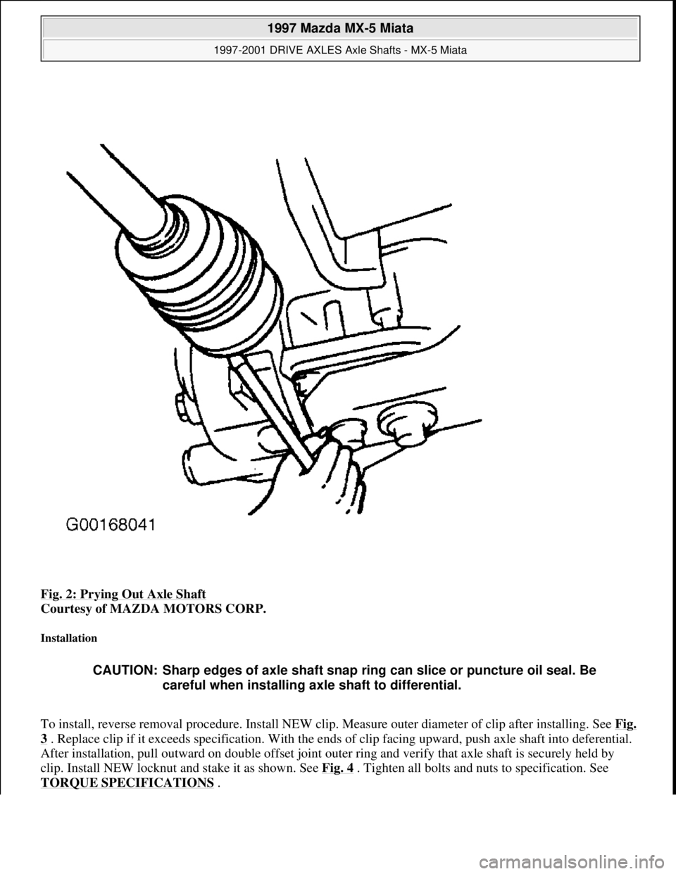
Fig. 2: Prying Out Axle Shaft
Courtesy of MAZDA MOTORS CORP.
Installation
To install, reverse removal procedure. Install NEW clip. Measure outer diameter of clip after installing. See Fig.
3 . Replace clip if it exceeds specification. With the ends of clip facing upward, push axle shaft into deferential.
After installation, pull outward on double offset joint outer ring and verify that axle shaft is securely held by
clip. Install NEW locknut and stake it as shown. See Fig. 4
. Tighten all bolts and nuts to specification. See
TORQUE SPECIFICATIONS
.
CAUTION: Sharp edges of axle shaft snap ring can slice or puncture oil seal. Be
careful when installing axle shaft to differential.
1997 Mazda MX-5 Miata
1997-2001 DRIVE AXLES Axle Shafts - MX-5 Miata
Microsoft
Sunday, July 05, 2009 1:51:37 PMPage 3 © 2005 Mitchell Repair Information Company, LLC.
Page 121 of 514
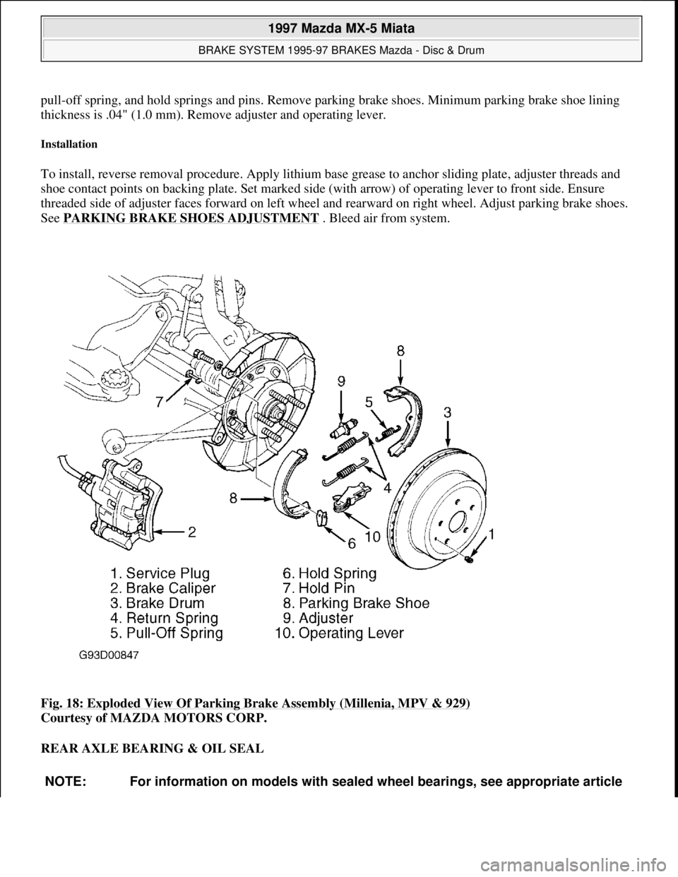
pull-off spring, and hold springs and pins. Remove parking brake shoes. Minimum parking brake shoe lining
thickness is .04" (1.0 mm). Remove adjuster and operating lever.
Installation
To install, reverse removal procedure. Apply lithium base grease to anchor sliding plate, adjuster threads and
shoe contact points on backing plate. Set marked side (with arrow) of operating lever to front side. Ensure
threaded side of adjuster faces forward on left wheel and rearward on right wheel. Adjust parking brake shoes.
See PARKING BRAKE SHOES ADJUSTMENT
. Bleed air from system.
Fig. 18: Exploded View Of Parking Brake Assembly (Millenia, MPV & 929)
Courtesy of MAZDA MOTORS CORP.
REAR AXLE BEARING & OIL SEAL
NOTE: For information on models with sealed wheel bearings, see appropriate article
1997 Mazda MX-5 Miata
BRAKE SYSTEM 1995-97 BRAKES Mazda - Disc & Drum
Microsoft
Sunday, July 05, 2009 1:51:03 PMPage 27 © 2005 Mitchell Repair Information Company, LLC.
Page 140 of 514
RECTIFIER/DIODE ASSEMBLY
1. Using an ohmmeter, check continuity of each diode in both directions (polarity). See Fig. 2
thru Fig. 4. If
diode shows high resistance in one direction and low resistance in other direction, diode is okay.
2. If diode shows low resistance in both directions, diode is shorted. If diode shows high resistance in both
directions, diode is open. If any diode is defective, replace rectifier assembly.
ROTOR & SLIP RINGS
Measure resistance between rotor slip ring contacts. See Fig. 5
thru Fig. 9 . If resistance is not within
specification, replace rotor. See ROTOR RESISTANCE SPECIFICATIONS
table. Check continuity
between individual slip rings and rotor core/shaft. If continuity exists, replace rotor.
ROTOR RESISTANCE SPECIFICATIONS
STATOR
Check continuity between stator coil leads and stator core. See Fig. 5
thru Fig. 9 . If continuity exists, replace
stator. Check continuity between leads of stator coil. If continuity does not exist, replace stator.
BRUSHES
Replace brushes if worn to limit line. See Fig. 5
thru Fig. 9 . Replace brush springs if corroded. For brush
replacement procedure, see OVERHAUL
.
Application(1) Ohms
Miata3.5-4.5
(1)If continuity does not exist, replace rotor.
1997 Mazda MX-5 Miata
GENERATOR & REGULATOR 1997 STARTING & CHARGING SYSTEMS Mazda - Generators & Regulators
Microsoft
Sunday, July 05, 2009 1:53:16 PMPage 4 © 2005 Mitchell Repair Information Company, LLC.
Page 160 of 514

Submerge other end of hose in container of brake fluid.
2. Fill reservoir with DOT 3 brake fluid. Have an assistant press and release clutch pedal several times, then
hold pedal down. With pedal pressed, loosen bleeder screw to let air and fluid escape.
3. Repeat step 2) until no more air bubbles emerge from hose. Tighten bleeder screw. Fill reservoir. Operate
clutch while inspecting for leaks. Check clutch and brake operation.
REMOVAL & INSTALLATION
CLUTCH ASSEMBLY
Removal (B2300, B2500, B3000 & B4000)
1. Disconnect negative battery cable. Shift transmission into Neutral. Remove gearshift lever. Raise and
support vehicle. Mark drive shaft flanges for installation reference. Remove drive shaft. Using Clutch
Disconnect Tool (T88T-70522-A), disconnect hydraulic line at transmission. See Fig. 2
. Plug hydraulic
line to prevent contamination. Disconnect wiring at transmission.
2. Remove starter. Remove exhaust components as necessary for clearance. On 4WD models, remove skid
plate and transfer case. On all models, secure transmission jack under transmission. Remove transmission
mount-to-crossmember nuts and bolts.
3. Remove nuts securing crossmember to frame side rails, and remove crossmember. Lower transmission
enough to gain access to transmission-to-engine block bolts. Remove transmission-to-engine block bolts.
Remove transmission.
4. If clutch parts are going to be reused, mark clutch cover and flywheel for reassembly reference. Loosen
pressure plate bolts evenly in crisscross pattern until springs are not under tension. Remove clutch cover
and clutch disc.
Inspection (B2300, B2500, B3000 & B4000)
1. Inspect disc for loose rivets, worn or defective springs, excessive wear, or oil contamination. Inspect
flywheel and clutch cover for burns, scoring, or grooves.
2. Measure flywheel and clutch cover runout. Resurface or replace flywheel and clutch cover if beyond
specification. See CLUTCH RUNOUT (MAXIMUM)
table.
3. Measure clutch disc runout. Replace disc if it is not to specification. See CLUTCH RUNOUT
(MAXIMUM) table. Inspect disc hub and input shaft splines for excessive wear. Hub must slide
smoothly on input shaft splines.
4. Inspect pilot bearing for wear. Apply inward pressure while rotating pilot bearing. If bearing sticks or has
excessive resistance, replace bearing. Check for tight fit in crankshaft. Replace as necessary. Inspect
release bearing for smooth operation, wear, damage, or looseness. Replace bearing as necessary.
CLUTCH RUNOUT (MAXIMUM)
ApplicationIn. (mm)
Disc0.028 (0.7)
Flywheel0.008 (0.20)
1997 Mazda MX-5 Miata
CLUTCH 1997-98 CLUTCHES Mazda - RWD
Microsoft
Sunday, July 05, 2009 1:36:47 PMPage 4 © 2005 Mitchell Repair Information Company, LLC.
Page 165 of 514
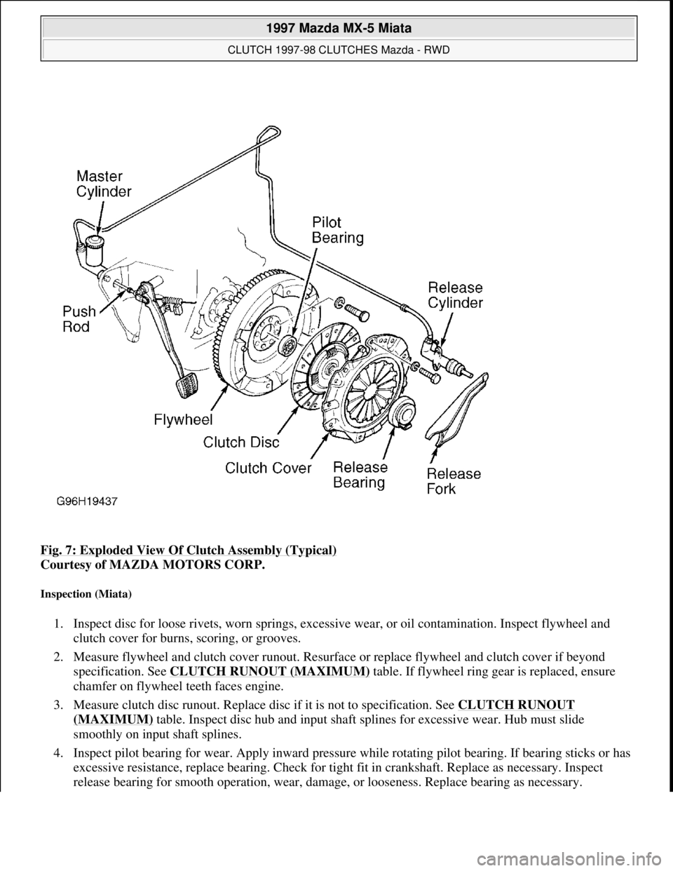
Fig. 7: Exploded View Of Clutch Assembly (Typical)
Courtesy of MAZDA MOTORS CORP.
Inspection (Miata)
1. Inspect disc for loose rivets, worn springs, excessive wear, or oil contamination. Inspect flywheel and
clutch cover for burns, scoring, or grooves.
2. Measure flywheel and clutch cover runout. Resurface or replace flywheel and clutch cover if beyond
specification. See CLUTCH RUNOUT (MAXIMUM)
table. If flywheel ring gear is replaced, ensure
chamfer on flywheel teeth faces engine.
3. Measure clutch disc runout. Replace disc if it is not to specification. See CLUTCH RUNOUT
(MAXIMUM) table. Inspect disc hub and input shaft splines for excessive wear. Hub must slide
smoothly on input shaft splines.
4. Inspect pilot bearing for wear. Apply inward pressure while rotating pilot bearing. If bearing sticks or has
excessive resistance, replace bearing. Check for tight fit in crankshaft. Replace as necessary. Inspect
release bearing for smooth operation, wear, damage, or looseness. Replace bearing as necessary.
1997 Mazda MX-5 Miata
CLUTCH 1997-98 CLUTCHES Mazda - RWD
Microsoft
Sunday, July 05, 2009 1:36:47 PMPage 9 © 2005 Mitchell Repair Information Company, LLC.
Page 166 of 514
Installation (Miata)
1. Lightly coat input shaft splines, release bearing, and fork contact areas with molybdenum disulfide
grease. Align clutch cover dowel holes with flywheel dowels. Tighten clutch cover bolts evenly in a
crisscross pattern to specification. See TORQUE SPECIFICATIONS
.
2. Place a wooden block on jack, and position jack under front of oil pan. Raise front of engine to ease
transmission installation. Install transmission. Tighten transmission-to-engine block bolts to specification.
See TORQUE SPECIFICATIONS
. Place jack (from front of engine) under transmission.
3. Raise transmission until level with engine. Position Power Plant Frame (PPF) in place. Install
PPF/differential mounting spacer, and tighten bolts to 27-38 ft. lbs. (37-51 N.m). Install and tighten PPF
side mounting bolts.
4. Install sleeve into PPF housing block. Install spacer and bolts. Install reamer bolt into front hole, and
tighten bolt. See Fig. 5
.
5. Install transmission-to-PPF bracket. Install remaining PPF bolts, and tighten to specification. See
TORQUE SPECIFICATIONS
. To complete installation, reverse removal procedure.
RELEASE BEARING & FORK
Removal (B2300, B2500, B3000 & B4000)
With transmission removed, twist release bearing and carrier assembly until preload spring pushes bearing
assembly from slave cylinder. See Fig. 8
.
Installation
Lubricate bearing bore and bearing carrier with NIGI No. 2 (lithium base) grease. Push release bearing
assembl
y onto clutch slave cylinder. NOTE: Front PPF-to-differential side mounting bolt is the reamer bolt, used to
align frame.
NOTE: Use only lithium base grease on release bearing. DO NOT use petroleum base
lubricants.
1997 Mazda MX-5 Miata
CLUTCH 1997-98 CLUTCHES Mazda - RWD
Microsoft
Sunday, July 05, 2009 1:36:47 PMPage 10 © 2005 Mitchell Repair Information Company, LLC.
Page 176 of 514
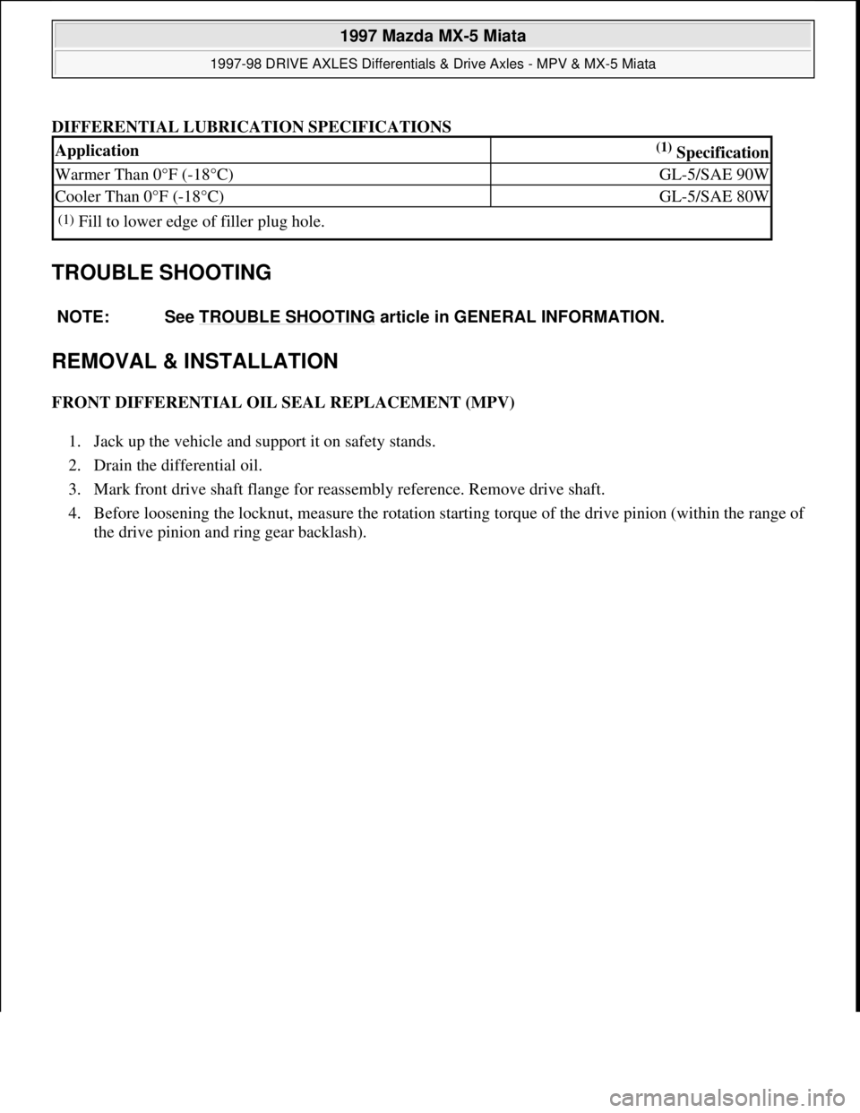
DIFFERENTIAL LUBRICATION SPECIFICATIONS
TROUBLE SHOOTING
REMOVAL & INSTALLATION
FRONT DIFFERENTIAL OIL SEAL REPLACEMENT (MPV)
1. Jack up the vehicle and support it on safety stands.
2. Drain the differential oil.
3. Mark front drive shaft flange for reassembly reference. Remove drive shaft.
4. Before loosening the locknut, measure the rotation starting torque of the drive pinion (within the range of
the drive pinion and rin
g gear backlash).
Application(1) Specification
Warmer Than 0°F (-18°C)GL-5/SAE 90W
Cooler Than 0°F (-18°C)GL-5/SAE 80W
(1)Fill to lower edge of filler plug hole.
NOTE: See TROUBLE SHOOTING
article in GENERAL INFORMATION.
1997 Mazda MX-5 Miata
1997-98 DRIVE AXLES Differentials & Drive Axles - MPV & MX-5 Miata
Microsoft
Sunday, July 05, 2009 1:52:42 PMPage 2 © 2005 Mitchell Repair Information Company, LLC.
Page 179 of 514
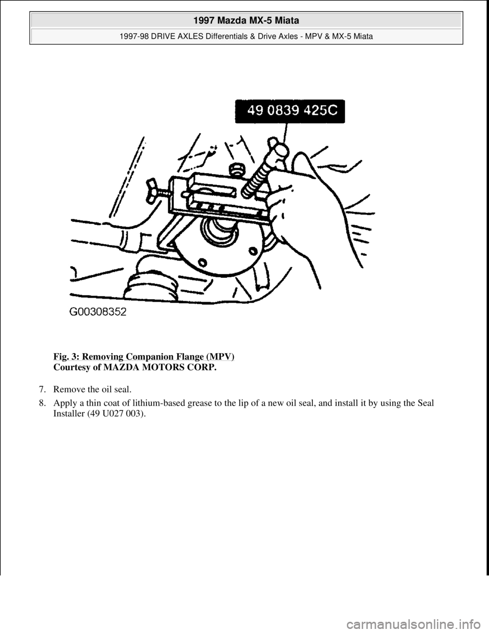
Fig. 3: Removing Companion Flange (MPV)
Courtesy of MAZDA MOTORS CORP.
7. Remove the oil seal.
8. Apply a thin coat of lithium-based grease to the lip of a new oil seal, and install it by using the Seal
Installer (49 U027 003).
1997 Mazda MX-5 Miata
1997-98 DRIVE AXLES Differentials & Drive Axles - MPV & MX-5 Miata
Microsoft
Sunday, July 05, 2009 1:52:42 PMPage 5 © 2005 Mitchell Repair Information Company, LLC.