Page 48 of 1600
4B-52 REAR AXLE
TROUBLESHOOTING
Refer to this Section to quickly diagnose and repair rear axle problems.
Each troubleshooting chart has three headings arranged from left to right.
(1) Checkpoint (2) Trouble Cause (3) Countermeasure
This Section is divided into five sub-sections:
1. Abnormal Rear Axle Noise
1) Noise when the engine is driving the vehicle
2) Noise when the vehicle is coasting
3) Intermittent noise
4) Noise when the vehicle is turning
5) Constant noise
2. Vibration
3. Oil Leakage
1) Differential carrier leakage
2) Axle case leakage
3) Axle case to inside hub leakage
4) Axle case to inside brake drum leakage
4. Power Not Being Transmitted to the Wheels (Propeller Shaft Operation is Normal)
Page 49 of 1600
REAR AXLE 4B-53
1. ABNORMAL REAR AXLE NOISE
1) Noise when the Engine is Driving the Vehicle
Checkpoint Trouble Cause Countermeasure
Replenish the gear oilInsufficient gear oil NG
Differential side bearingAdjust the differential side
bearing preload
Replace the drive pinion
bearings
Adjust the drive pinion bearing
preload
Replace the gear oil
Loose differential side
bearings
W orn drive pinion bearings
Loose drive pinion bearings
W rong or poor grade gear oil
Drive pinion to ring gear
backlash
Drive pinion end play
Adjust the backlashToo much or too little backlash
Continued on the next pageOK OK
NG NG NG NG NG
OK
OK
Rear axle gear oil
Replace the differential side
bearingsW orn differential side bearings NG
Page 66 of 1600
FRONT WHEEL DRIVE 4C1-3
MAIN DATA AND SPECIFICATIONS
FRONT AXLE AND DIFFERENTIAL
Ring gear size mm(in) 167 (6.6) 194 (7.6)
Axle tube
Type It consists of the duce, a cast iron housing and the Axle tube.
Gear type Hypoid
Gear ratio (to 1)
HEC.2.0L engine - -
HEC.2.2L engine 4.555 4.777
Differential type Two pinion
Oil capacity liter 1.0 1.4
(US/UK gal.) (0.26/0.22) (0.4/0.33)
Axle shaft type Constant velocity joint (Birfield joint type and double offset joint).
Hub locking type Automatic locking and Manual locking free wheel hubs.
FRONT PROPELLER SHAFT
Transmission type MSG MUA
Outside diameter mm(in) 40 (1.57) 40 (1.57)
Inside diameter mm(in) 33 (1.30) 32 (1.26)
Length mm(in) 505 (19.88) 471 (18.54)
(between two spiders center)
Page 565 of 1600

CLUTCH 7C-25
3. Check that the driven plate moves smoothly on the
transmission top gear shaft spline.
Minor ridges on the top gear shaft spline may be removed
with an oil stone.
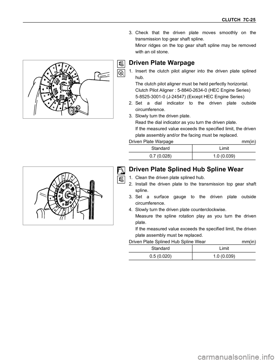
Driven Plate Warpage
1. Insert the clutch pilot aligner into the driven plate splined
hub.
The clutch pilot aligner must be held perfectly horizontal.
Clutch Pilot Aligner : 5-8840-2634-0 (HEC Engine Series)
5-8525-3001-0 (J-24547) (Except HEC Engine Series)
2. Set a dial indicator to the driven plate outside
circumference.
3. Slowly turn the driven plate.
Read the dial indicator as you turn the driven plate.
If the measured value exceeds the specified limit, the driven
plate assembly and/or the facing must be replaced.
Driven Plate Warpage mm(in)
Standard Limit
0.7 (0.028) 1.0 (0.039)
Driven Plate Splined Hub Spline Wear
1. Clean the driven plate splined hub.
2. Install the driven plate to the transmission top gear shaft
spline.
3. Set a surface gauge to the driven plate outside
circumference.
4. Slowly turn the driven plate counterclockwise.
Measure the spline rotation play as you turn the driven
plate.
If the measured value exceeds the specified limit, the driven
plate assembly must be replaced.
Driven Plate Splined Hub Spline Wear mm(in)
Standard Limit
0.5 (0.020) 1.0 (0.039)
Page 567 of 1600
CLUTCH 7C-27
CLUTCH CONTROL
REMOVAL AND INSTALLATION
Except 6VD1 Engine
Removal Steps
1. Pin
2. Jaw joint pin
3. Pedal assembly
4. Oil line
5. Master cylinder assembly
6. Oil line
7. Slave cylinder assembly
8. Damper cylinder assembly
Installation Steps
To install, follow the removal steps in the
reverse order.
Page 570 of 1600
7C-30 CLUTCH
MASTER CYLINDER (Except 6VD1 Engine)
DISASSEMBLY
Repair Kit
Disassembly Steps
1. Oil tank band
2. Oil tank assembly
3. Joint
4. Lock nut
5. Dust cover6. Stopper ring
7. Stopper
8. Push rod
9. Piston assembly
10. Cylinder body
Important : Take care not to disassemble the push rod stopper for master cylinder which calk to the master cylinder
body due to the component parts do not disassemble.
Page 580 of 1600
7C-40 CLUTCH
HYDRAULEC DAMPER CYLINDER (Except 6VD1 Engine)
INSPECTION AND REPAIR
Make the necessary adjustments, repairs, and part replacements if excessive wear or damage is discovered during
inspection.
Visually check for oil leakage and other damage.
If oil leakage or other damage is discovered during the
inspection; the damper cylinder assembly must be replaced as
a unit.