1997 ISUZU TFR SERIES check engine
[x] Cancel search: check enginePage 1033 of 1800

1
CONTENTS
Page
Isuzu TFR/S Immobilizer System lntroduction........................................................................ 3
What your organization should provide for your customer .............................................. 3
System outline ........................................................................................................................... 4
While the system is On.........................................................................................................4
What happens without proper transponder operation? .................................................... 4
No proper transponder is available, what should be done for the system? ................... 4
Caution to the operation......................................................................................................4
Summary of operation ..........................................................................................................4
Illustration of lnstrument panel ........................................................................................... 5
Immobilizer system Gas Engine (6VD1 3.2L/C22NE 2.2L/22LE 2.2L/2.0LE 2.0L) ................. 6
Immobilizer system Diesel Engine (4JG2 3.1L/4JB1 2.8L/4JA1 2.5L) ................................... 7
Electrical Equipment Instruments ........................................................................................... 8
Location of Components...................................................................................................... 8
Electrical Equipment – Instruments ........................................................................................ 9
Terminal Assignment of wiring Harness Connector, Immobilizer Controller ................. 9
Electrical Equipment – Instruments ...................................................................................... 10
Function (Continued)..........................................................................................................10
Car Pass Card..................................................<0011001100110011001100110011001100110011001100110011001100110011001100110011001100110011001100110011001100110011001100110011001100110011001100110011001100110011001100110011001100110011001100110011001100
11001100110011001100110011001100110011001100110011>10
Checking Component Required ........................................................................................ 11
Tech 2 illustration ............................................
................................................................... 11
Important information on Programming................................................................................ 12
Security code ...................................................................................................................... 12
1. Entering a code .............................................................................................................. 12
2. Getting started ............................................................................................................... 13
3. Transponder ................................................................................................................... 14
Transponder program .................................................................................................... 14
Erase transponder key................................................................................................... 15
4. Reset Immobilizer ICU (Immobilizer Control Unit) (Gas Engine Model).................... 16
5. Programming ICU, ECM ................................................................................................ 17
Important ............................................................................................................................. 23
Page 1034 of 1800

2
Page
Loss of car pass ...............................................<0011001100110011001100110011001100110011001100110011001100110011001100110011001100110011001100110011001100110011001100110011001100110011001100110011001100110011001100110011001100110011001100110011001100
11001100110011001100110011001100110011001100110011>... 24
Diagnostic procedure.............................................................................................................. 26
Diagnostic procedure.............................................................................................................. 27
1. 12V power is not supplied to lCU. ................................................................................ 27
2. Engine does not start after steering assembly is repaired. ....................................... 27
3. If engine does not start after ICU replacement, check part number (01MY)............. 27
4. Electrical wiring ............................................................................................................. 32
Page 1036 of 1800

4
System outline
The immobilizer system consists of the four major components, which are DDS-1, Engine Control Module (ECM),
Immobilizer Control Unit (lCU), and transponder.
See page 6 for Gas engine, page 7 for Diesel Engine.
This system can be activated by a correctly programmed transponder and starter switch is set to OFF. This system
can be deactivated by a correctly programmed Transponder Key connected with a correctly programmed ECM and
a correctly programmed immobilizer lCU.
While the system is On
ln case of Gas engine;
The starter cut off relay deactivates function of starter, and the fuel injector power source is deactivated also.
ln case of Diesel engine;
The starter cut off relay deactivates function of starter, and the pump is deactivated also.
What happens without proper transponder operation?
One of the function of transponder is to deactivate or activate starter function. lf the proper transponder is not used,
starter cannot be operated. Because starter cut off relay stays On, cranking engine is not possible.
After the starter cut off relay is deactivated, transponder signal triggers to let immobilizer lCU calculate by
transponder address signal and immobilizer algorithm.
When the result matches with necessary condition, it makes injector power source be activated.
If transponder does not send correct signal, immobilizer lCU and ECM do not activate injector system On. Therefore
the vehicle cannot be operated.
No proper transponder is available, what should be done for the system?
When any proper transponder is not available, a new transponder should be programmed. Up to 5 transponders
can be provided with Tech 2 and by proper procedure. See pages 14-15.
In addition to the absence of proper transponder, it may happen particular secret code to the particular vehicle is
missing. ln this case, the secret code must be provided by your organization (refer to “loss of car pass” on pages
24, 25). Otherwise transponder cannot be programmed in any way.
lf the essential tool Tech 2 for programming and proper software for Tech 2 are not available, there is no permanent
way to fix system. Temporary replace with new ECM, new ECU and new transponder without any secret code can
make the system be deactivated, but it does not last long. Such a replacement does not solve any condition. Even
after replacement, the system is activated automatically in short time and then no operation of the vehicle can be
made in any way.
Tech 2 should be provided in your organization. See page 12.
Caution to the operation
lf an attempt is made to start the engine while the immobilizer system is activated, the CHECK ENGINE indicator
flashes and the engine will not start. See the illustration at the bottom of this page.
Summary of operation
Switch On: Set the ignition and starter switch to OFF.
(Activate)
Switch Off: Set the ignition and starter switch to ON by using the transponder key.
(Deactivate)
Page 1041 of 1800
9
Electrical Equipment – Instruments
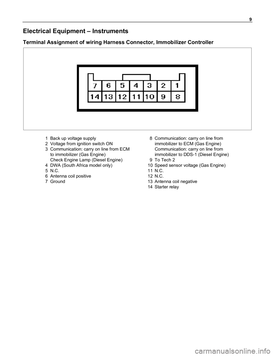
Terminal Assignment of wiring Harness Connector, Immobilizer Controller
1 Back up voltage supply
2 Voltage from ignition switch ON
3 Communication: carry on line from ECM
to immobilizer (Gas Engine)
Check Engine Lamp (Diesel Engine)
4 DWA (South Africa model only)
5N.C.
6 Antenna coil positive
7 Ground8 Communication: carry on line from
immobilizer to ECM (Gas Engine)
Communication: carry on line from
immobilizer to DDS-1 (Diesel Engine)
9To Tech 2
10 Speed sensor voltage (Gas Engine)
11 N.C.
12 N.C.
13 Antenna coil negative
14 Starter relay
Page 1053 of 1800
21
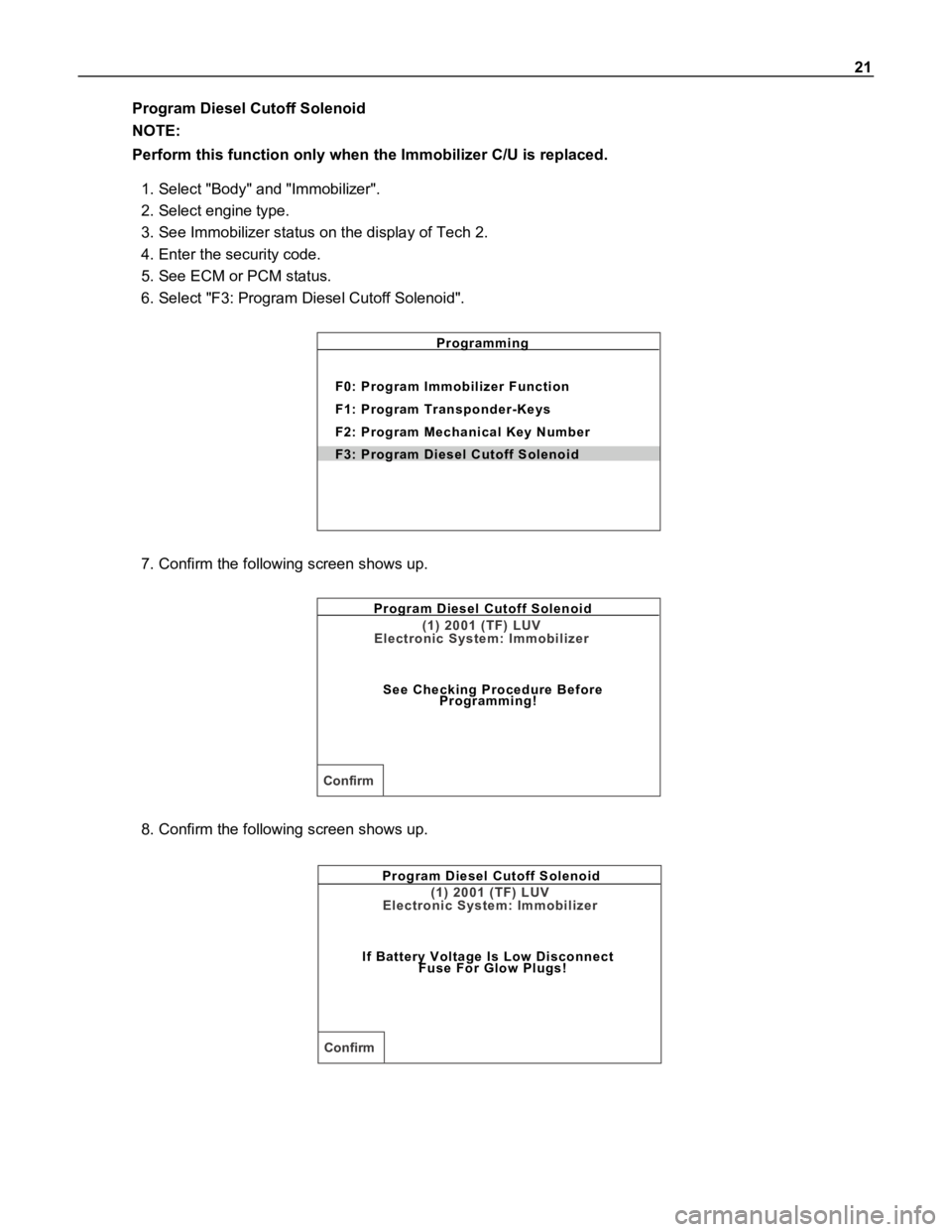
Program Diesel Cutoff Solenoid
NOTE:
Perform this function only when the Immobilizer C/U is replaced.
1. Select "Body" and "Immobilizer".
2. Select engine type.
3. See Immobilizer status on the display of Tech 2.
4. Enter the security code.
5. See ECM or PCM status.
6. Select "F3: Program Diesel Cutoff Solenoid".
Programming
F0: Program Immobilizer Function
F1: Program Transponder-Keys
F2: Program Mechanical Key Number
F3: Program Diesel Cutoff Solenoid
7. Confirm the following screen shows up.
Program Diesel Cutoff Solenoid
See Checking Procedure Before
Programming!
(1) 2001 (TF) LUV
Electronic System: Immobilizer
Confirm
8. Confirm the following screen shows up.
Program Diesel Cutoff Solenoid
If Battery Voltage Is Low Disconnect
Fuse For Glow Plugs!
(1) 2001 (TF) LUV
Electronic System: Immobilizer
Confirm
Page 1055 of 1800
23
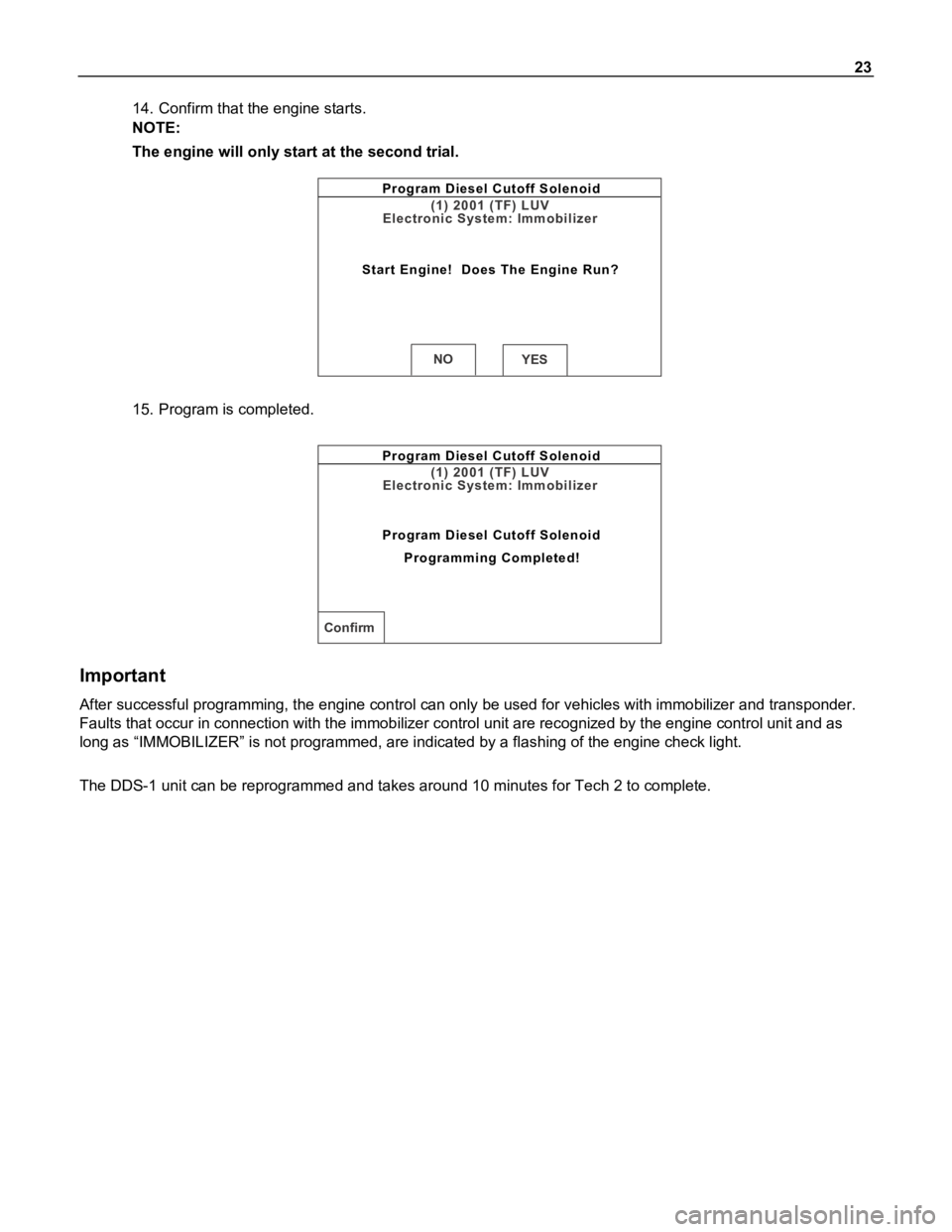
14. Confirm that the engine starts.
NOTE:
The engine will only start at the second trial.
Program Diesel Cutoff Solenoid
Start Engine! Does The Engine Run?
(1) 2001 (TF) LUV
Electronic System: Immobilizer
NOYES
15. Program is completed.
Program Diesel Cutoff Solenoid
Program Diesel Cutoff Solenoid
Programming Completed!
(1) 2001 (TF) LUV
Electronic System: Immobilizer
Confirm
Important
After successful programming, the engine control can only be used for vehicles with immobilizer and transponder.
Faults that occur in connection with the immobilizer control unit are recognized by the engine control unit and as
long as “IMMOBILIZER” is not programmed, are indicated by a flashing of the engine check light.
The DDS-1 unit can be reprogrammed and takes around 10 minutes for Tech 2 to complete.
Page 1059 of 1800
27
Diagnostic procedure
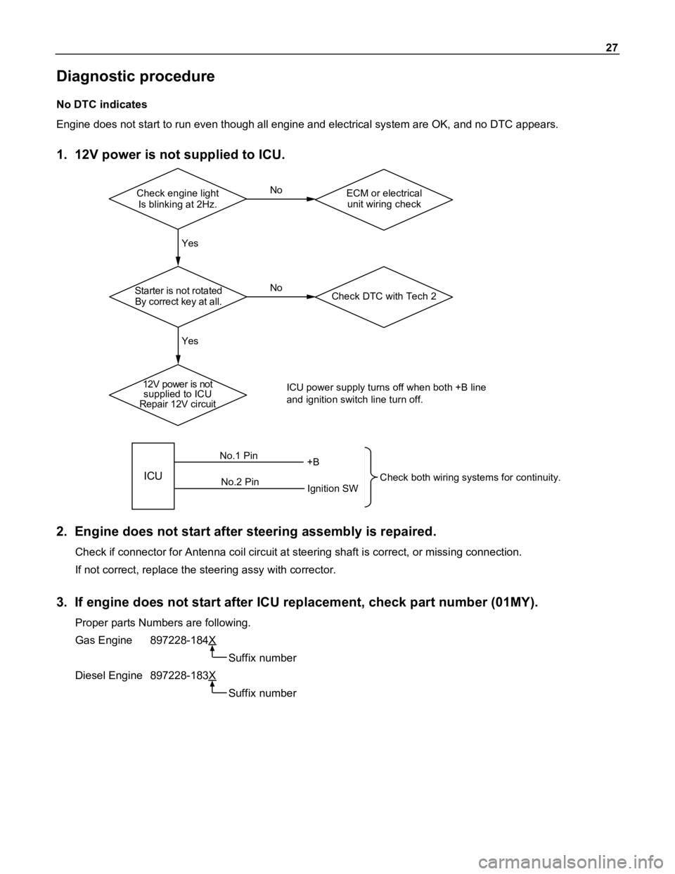
No DTC indicates
Engine does not start to run even though all engine and electrical system are OK, and no DTC appears.
1. 12V power is not supplied to ICU.
Check engine light
Is blinking at 2Hz.ECM or electrical
unit wiring check No
Yes Yes
Starter is not rotated
By correct key at all.Check DTC with Tech 2
12V power is not
supplied to ICU
Repair 12V circuitICU power supply turns off when both +B line
and ignition switch line turn off.
ICU
No.1 Pin
No.2 Pin+B
Ignition SWCheck both wiring systems for continuity.
No
2. Engine does not start after steering assembly is repaired.
Check if connector for Antenna coil circuit at steering shaft is correct, or missing connection.
If not correct, replace the steering assy with corrector.
3. If engine does not start after ICU replacement, check part number (01MY).
Proper parts Numbers are following.
Gas Engine 897228-184X
Suffix number
Diesel Engine 897228-183X
Suffix number
Page 1061 of 1800
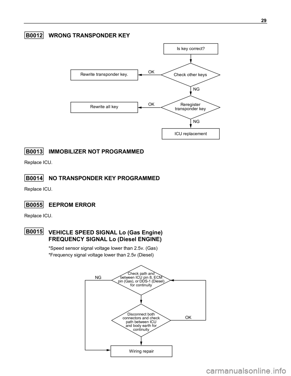
29
B0012WRONG TRANSPONDER KEY
Is key correct?
ICU replacement
Rewrite transponder key.
Rewrite all keyOK
OKCheck other keys
Reregister
transponder keyNG
NG
B0013IMMOBILIZER NOT PROGRAMMED
Replace ICU.
B0014NO TRANSPONDER KEY PROGRAMMED
Replace ICU.
B0055EEPROM ERROR
Replace ICU.
B0015VEHICLE SPEED SIGNAL Lo (Gas Engine)
FREQUENCY SIGNAL Lo (Diesel ENGINE)
*Speed sensor signal voltage lower than 2.5v. (Gas)
*Frequency signal voltage lower than 2.5v (Diesel)
Check path and
between ICU pin 8, ECM
pin (Gas), or DDS-1 (Diesel)
for continuity
Disconnect both
connectors and check
path between ICU
and body earth for
continuity
W iring repair
NG
OK