1997 HONDA CR-V front center cover
[x] Cancel search: front center coverPage 118 of 1395
Valve Seals
Replacement (cylinder head removal not required)
The procedure shown below applies when using the in-
car valve spring compressor (Snap-on YA8845 with
YA8845-2A 7/8" auachment). Use approved eye protec-
tion.
1. Turn the crankshaft so that the No. 1 and the No. 4
pistons are at top dead center (TDC).
2. Remove the cylinder head cover.
3. Remove the distributor.
4. Loosen and disconnect the timing belt from the
camshaft pulleys.
5. Remove the camshaft holder bolts. then remove the
camshaft holders, the camshafts and rocker arms.
lntake Valve Seals
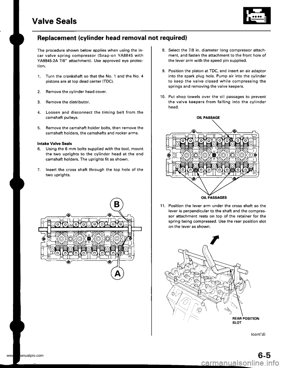
6. Using the 6 mm bolts supplied with the tool, mount
the two uprights to the cylinder head at the end
camshaft holders. The uprights fit as shown.
7. Insert the cross shaft through the top hole of the
two uprights,
at.
9.
Select the 7/8 in. diameter long compressor attach-
ment, and fasten the attachment to the front hole of
the lever arm with the speed pin supplied.
Position the piston at TDC, and insen an air adaptor
into the spark plug hole. Pump air into the cylinder
to keep the valve closed while compressing the
springs and removing the valve keepers.
10. Put shop towels over the oil passages to prevent
the valve keepers from falling into the cylinder
head.
Position the lever arm under the cross shaft so the
lever is perpendicular to the shaft and the compres-
sor attachment rests on top of the retainer for the
spring being compressed. Use the rear position slot
on the lever as shown,
't1.
OIL PASSAGE
OIL PASSAGES
(cont'd)
6-5
www.emanualpro.com
Page 982 of 1395
Body
Bumpers
Front Bumper Removal and
fnstaflation .........20-72
Rear Bumper Removal and
fnstaflation .........20-74
'Dashboard
lnstrument Panel Removal and
lnstallation .........20-47
Driver's Dashboard Lower Cover and
Knee Bolster Removal and
Installation .........20-48
Glove Box Removal and
lnstallation .........20-49
Center Pocket Removal and
lnstallation .........20-49
Center Dashboard Lower Cover
Removal and lnstallation ............ 20-50
Center Panel Removal and
lnstallation .........20-50
Power Window Switch Removal and
lnstallation .........20-51
Center Air Vent Removal and
lnstallation .........20-51
Side Air Vent Removal and
fnstallation .........20-52
Side Defogger Trim Removal and
fnstallation .........20-52
Dashboard Removal and
lnstallation .........20-53
Dashboard Frame Replacement ..... 20-55
Doors
Component Location Index
Front Door ,,...,,,,20-2
Rear Door ...........20-4
Tailgate Door ................................ 20-6
Fenderwell
Front Wheelwell Protector
Replacement .....20-89
Inner Fender Replacement .,.....,.,.... 20-89
Rear Wheelwell Protectol
Replacement .....20-90
Fuel Pipe Protector Replacement ... 20-90
Rear Air Outlet Replacement .......... 20-91
*Frame Repair Chart .............................. 20-106
Front Grille
Repf acement .........20-77
Glass
Component Location Index ............ 20-29
Hood
Replacement ......,,,20-75
Adjustment ............20-76
*lnterior Trim
Component Location Index ............ 20-40
Mirrors
Component Location Index .........,,, 20-26
Moldings
Roof Molding Replacement ............ 20-84
Door Moldings Replacement .......... 20-85
Openers
Component Location Index ............ 20-92
Rear Hatch Glass
Replacement .........20-74
Disassembly and Reassembly ........ 20-79
Adiustment ............20-81
Rear Weatherstrip Replacement .... 20-83
Seats
Component Location Index ............ 20-56
Side Sill Panel
Repfacement .........20-87
Spare Tire Cover
Emblem Installation ........................ 20-88
Sub-frame ..................20-104
Wiper/Washer
Component Location lndex ,,,,,....... 20-97
www.emanualpro.com
Page 1021 of 1395
lnterior Trim
20-40
CARGO FRONTSPACER(see page 20 43)
FRONT PILLARTRIM(see page 20-41)
TRUNK FLOOREXTENSION(see page 20 43)
HEADLINERRemoval and lnstallation,page 20-44
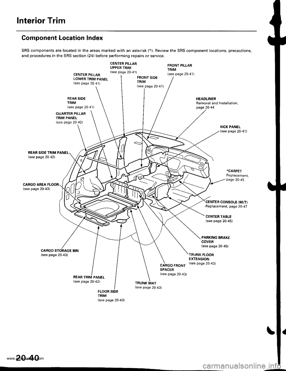
Component Location Index
SRS components are located in the areas marked with an asterisk (*). Review the SRS component locations, precautions,
and procedures in the SRS section (24) before performing repairs or service.
CENTER PILLARUPPER TRIM(see page 20 41)CENTER PILLARLOWER TRIM PANEL(see page 20 41)
FRONT SIDETRIM(see page 20-41)
BEAR SIDETEIM(see page 20'41)
OUARTER PILLARTRIM PANEL(see page 20 42)
*CARPET
Replacement,page 20 45
CENTER CONSOLE IM/T}Replacement, page 20-47
CENTEN TABLE(see page 20-45)
PARKING BRAKECOVER(see page 20-45)
TRIM
www.emanualpro.com
Page 1022 of 1395
Removal and Installation
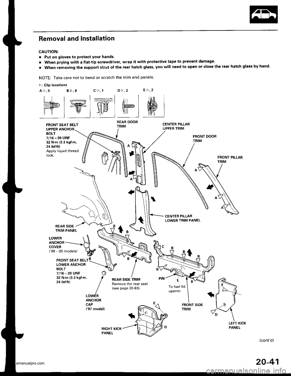
CAUTION:
. Put on gloves to protect your hands,
. When prying with a tlat-tip screwdrivel, wrap it with protective tape to prevent damage.
. When removing the support strut of the rear hatch glass, you will need to open or close the rear hatch glass by hand.
NOTE: Take care not to bend or scratch the trim and panels.
>: Clio locations
a>,5c>, 1o>.2e>,2B >,8
UPPERBOLT7/16 - 20 UNF32 N.m {3.3 kgf.m,24 rbt.ft)Apply liquid thread
CENTER PILLARLOWER TRIM PANEL
LOWERANCHOBCOVER('98 00 models)
{cont'd)
I l_lss-l , | 'rrl
elElw"lel sl
FRONT SEAT BELT
FRONT SEAT BELLOWER ANCHORBOLT7/15 - 20 UNF32Nm(3.3kgf.m,24 tbt.ftl
ANCHORCAP('97 model)
REAR DOORTRIM
REAR SIDE TRIMtlemove the rear seat(see page 20 63).
REAR SIDE
20-41
www.emanualpro.com
Page 1025 of 1395
lnterior Trim
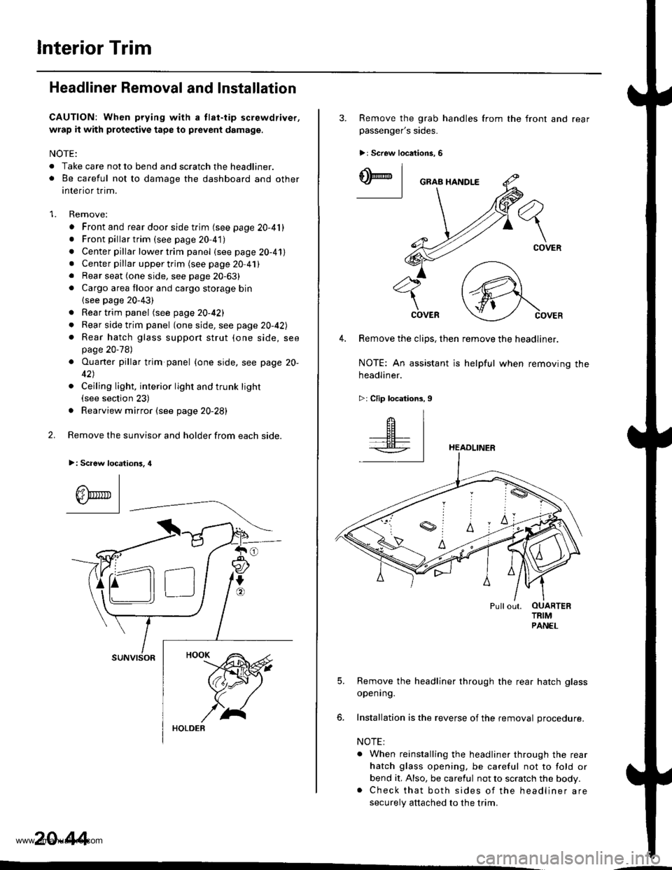
Headliner Removal and Installation
CAUTION: When prying with a tlat-tip screwdriver,
wrap it with protective tape to prevent damage.
NOTE:
. Take care not to bend and scratch the headliner.o Be careful not to damage the dashboard and other
interior trim.
1. Remove:
. Front and rear door side trim (see page 20-41). Front pillartrim (see page 20-41)
. Center pillar lower trim panel (see page 20-41). Center pillar upper trim (see page 20 41). Rear seat (one side, see page 20-63). Cargo area floor and cargo storage bin
{see page 20-43)
. Rear trim panel (see page 20-421
. Rear side trim panel (oneside, see page 20-42l,
. Rear hatch glass support strut (one side, seepage 20-78)
. Ouaner pillar trim panel {one side, see page 20-
42)
. Ceiling light, interior light and trunk light(see section 23)
. Rearview mirror (see page 20-28)
2. Remove the sunvisor and holder from each side.
>: Scaew location3, 4
I
A\"r- |Yr* || -
suNvtsoR
20-44
3. Remove the grab handles from
passenger's sides.
>r Screw locations, 6
the front and rear
ry_l
COVER
4. Remove the clips, then remove the headliner.
NOTE: An assistant is helpful when removing the
headliner.
>: Clip locations,9
HEADLINER
Pullout. OUARTERTRIMPANEL
5. Remove the headliner through the rear hatch glass
openrng.
6. Installation is the reverse of the removal procedure.
NOTE:
. When reinstalling the headliner through the rear
hatch glass opening, be careful not to fold or
bend it, Also, be careful not to scratch the body.. Check that both sides of the headliner are
securely attached to the trim.
www.emanualpro.com
Page 1026 of 1395
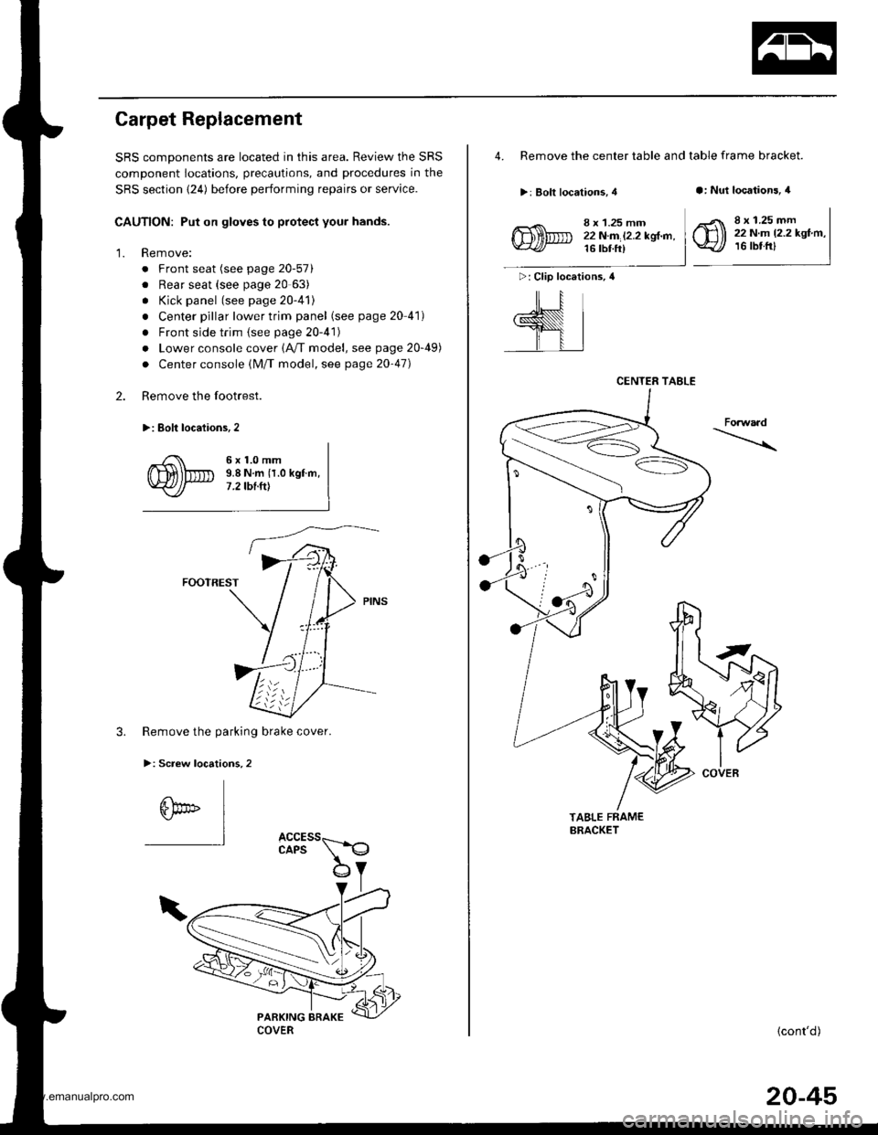
Carpet Replacement
SRS comDonents are located in this area. Review the SRS
component locations, precautions, and procedures in the
SRS section {24) before performing repairs or service.
CAUTION: Put on gloves to protect your hands.
Remove:
. Front seat (see page 20-571
. Rear seat (see page 20 63)
. Kick panel (see page 20-41)
. Center pillar lower trim panel (see page 20 41)
. Front side trim {see page 20-41)
. Lower console cover 1A,/T model, see page 20-49)
. Center console (lM/T model, see page 2o-47)
Remove the footrest.
>: Eolt locaiions,2
2.
'1.
6x1.0mm9.8 N.m {1.0 kgf.m,7 .2 tbt.ttt
FOOTREST
3. Remove the parking brake cover.
>: Screw locations,2
6bo" I"l
4. Remove the center table and table frame bracket.
>: Bolt locations, 4a: Nut locations, 4
>: Clip locations, 4
ill
,l
8 x 1.25 mm22N.m l2.2kgl.n,16 tbt ft)
8 x 1.25 mm22 N.m 12.2 kgf.m,16 tbtfrl
Forwaad
TABLE FRAMEBRACKET
{cont'd)
CENTER TABLE
COVER
20-45
www.emanualpro.com
Page 1146 of 1395
A/G System Service
Performance Test
The performance test will helD determine if the air con-
ditioner system is operating within specifications.
Use only service equipment that is U.L.-listed and is cer-
tified to meet the requirements of SAE J2210 to remove
HFC-134a (R-134a) from the air conditioner svstem.
CAUTION: Exposure to air condiiioner r€trigerant and
lubricant vapor or mist can irritate €yes, nose and
throat. Avoid bre8thing the air conditioner retrige.ant
and lubricant vapor or mist,
lf accidental system discharge occurs. ventilate work
area before resuming service.
R-134a service equipment o. vehicle air conditioner sys-
tems should not be pressure tested or leak tested with
comDressed air.
@ some mixtur€s ol air and R-134a have becn
shown to be combuslible at olsvated pressures and can
result in lire or explosion causing iniury or property
damage. Never use compressed air to prgssure test R-
13i[a service equipment or vehicle air conditioner sys.
tems.
Additional health and safety information may be obtained
from the refrigerant and lubricant manufacturers.
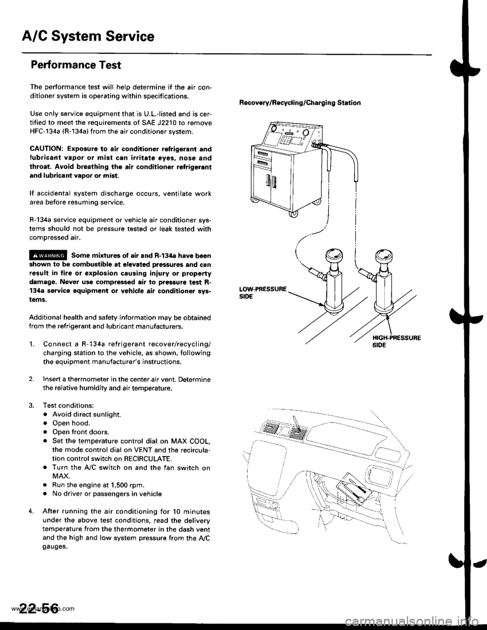
Recovory/Recycling/charging station
LOW.PRESSURESIDE
1.Connect a R-134a refrigerant recover/recycling/
charging station to the vehicle, as shown. following
the equipment manufacturer's instructions,
Insen a thermometer in the center air vent. Determine
the relative humidity and air temperature.
Test conditions:
. Avoid direct sunlight.
o Open hood.
. open front doors.
. Set the temperature control dial on MAX COOL,
the mode control dial on VENT and the reci.cula-
tion control switch on RECIRCULATE.
. Turn the A,/C switch on and the fan switch on
MAX.
. Run the engine at 1,500 rpm.
. No driver or passengers in vehicle
After running the air conditioning for 10 minutes
under the above test conditions, read the deliverv
temperature from the thermometer in the dash vent
and the high and low system pressure from the Ay'Cgauges.
2.
22-56
www.emanualpro.com
Page 1241 of 1395
Adjustment
Bstore adiusting the headlights:
. Park the vehicle on level ground
. Make sure the fuel tank is tull
. The driver or someone who weighs the same should
sit in the driver's seat.
. Load the trunk with the items you usually carry'
. Push down on the front and rear bumpers several
times to make sure the vehicle is sitting normally'
CAUTION: Halogen headlights become very hot in use;
do not touch them or the atiaching hardware immedi-
ately after they have been turned off.
1. ODen the hood.
2. Remove the left inner fender {see section 20).
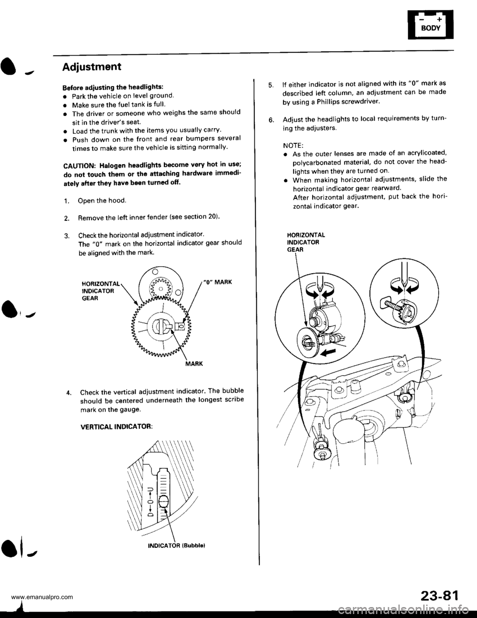
3. Checkthe horizontal adjustment indicator.
The "0" mark on the horizontal indicator gear should
be aligned with the mark.
"0" MARK
Check the vertical adjustment indicator. The bubble
should be centered underneath the longest scribe
mark on the gauge.
VERTICAL INDICATOR:
ol-
)
5.lf either indicator is not aligned with its "0" mark as
described left column, an adjustment can be made
by using a Phillips screwdriver.
Adjust the headlights to local requirements by turn-
ing the adjusters.
NOTE:
. As the outer lenses are made of an acrylicoated,
polycarbonated material, do not cover the head-
lights when they are turned on
. When making horizontal adiustments, slide the
horizontal indicator gear rearward.
After horizontal adjustment, put back the hori-
zontal indicator gear.
HORIZONTALINDICATORGEAR
23-A1
www.emanualpro.com