Page 1256 of 1395
Accessory Socket
Accessory Socket Test/Replacement
Front Accessory Socket:
1. Remove the center dashboard lower cover (see sec-
tion 20).
Disconnect the 2P connector from the front accessory
socket.
Inspect the connector terminals to be sure they are
all making good contact.
2.
lf the terminals are bent, loose or corroded, repair
them as necessary, and recheck the system.
lf the terminals look OK, go to step 4.
ACCESSORYSOCKET
Turn the ignition switch to ACC (l), and check for
voltage between the No. 1 and No. 2 terminals.
. There should be battery voltage.
. lf there is no battery voltage, check for:- blown No.27 (10 A) fuse in the under-dash
fuse/relay box.- poor ground (G401, G402).- an open in the wire.
23-96
5. If all the tests prove OK, replace the front accessory
socket.
PBOTECTOB
FACE PANEL
www.emanualpro.com
Page 1300 of 1395
Seat Belts
Component Location Index
SRS components are located in the parts areas marked with an asterisk {*). Review the SRS component locauons, precau-tions, and procedures in this section (24) before performing repairs or service (,98 _ 00 models).
CHILD SEAT TETHEN ANCHORlnstallation -'97 99 models, page 24-10Removal/lnstallation - '00 model, page 24-11
CHILD SEAT TETHERANCHOR COVER ('00 mod€tl
REAR SEAT BELT BUCKLE/CENTER BELT TONGUE(see page 24-7).FRONT SEAT BELTReplacement, page 24 3Inspection, page 24-9
BELT EUCKLES(see page 24 5)
24-2
,--.4
www.emanualpro.com
Page 1301 of 1395

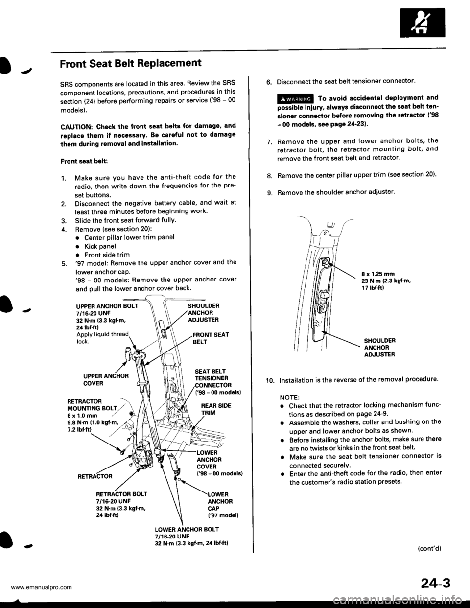
JFront Seat Belt RePlacement
SRS components are located in this area. Review the SRS
component locations, precautions, and procedures in this
section (24) before performing repairs or service ('98 - 00
models).
CAUTION: Check the front seat bslts for damago. and
replaco thom if necessary. Be careful not to damage
them during removal and in3tallation'
Front scat bolt:
1. Make sure you have the anti-theft code for the
radio, then write down the frequencies for the pre-
set buttons.
2. Disconnect the negative battery cable, and wait at
least three minutes before beginning work.
3. Slide the front seat forward fully.
4. Bemove (see section 20):
. Center pillar lower trim Pane
. Kick oanel
. Front side trim
5. '97 model: Remove the upper anchor cover and the
lower anchor caP.'98 - oO models: Remove the upper anchor cover
and pull the lower anchor cover back.
UPPEN ANCHOR BOLT
7/1&20 UNF32 N.m (3.3 kgt'm.24 tbf.ft)
SHOULDERANCHORADJUSTER
Apply liquid threadlock.
9.8 N.m (1.0 kgt.m,?.2 tbtft)
UPPERCOVER
RETRACTORMOUNTING BOLTZ,,Gx1.0mm ./
SEAT BELTTENSIONER
{'98 - 0o modols)
REAR SIDE
ANCHORCOVERl'98 - 00 models)
ANCHORCAP('97 modell
RETRACTOR BOLT7/1&20 UNF32 N.m 13.3 kgt m,24 tbt.ft)
LOWER ANCHOR BOLT?,/1&20 UNF32 N.m {3.3 kgf.m, 2,1 lbf.ftl
o.Disconnect the seat belt tensiongr connector.
@ To avoid accidontal deployment and
possibte inlury, always disconnect the soat bsh ton-
sion€r connoctor bofore rsmoving th6 retractor l'98
- 00 modsls, se€ pa ge 21-231 .
Remove the uDDer and lower anchor boits, the
retractor bolt, the retractor mounting bolt, and
remove the front seat belt and retractor.
Remove the center pillar upper trim (see section 20).
Remove the shoulder anchor adjuster.
7.
9.
8.
I x 1.25 mm23 N.m 12.3 kgt.m,1? tbf.ft)
SHOULDERANCHORADJUSTER
10. lnstallation isthe reverse of the removal procedure.
NOTE:
Check that the retractor locking mechanism func-
tions as described on Page 24-9.
Assemble the washers, collar and bushing on the
uooer and lower anchor bolts as shown.
Eefore installing the anchor bolts, make sure there
are no twists or kinks in the front seat belt.
Make sure the seat belt tensioner connector ls
connected securelv.
Enter the anti-theft code for the radio, then enter
the customer's radio station presets
(cont'd)
24-3
www.emanualpro.com
Page 1303 of 1395
Ssat belt buckle:
1. Slide the front seat forward fully
2. Remove the center cover (see section 20).
3. Driver's: Disconnect the seat belt switch connector,
and detach the harness clips from the seat cushion
frame.
>: Clip locations
To seat beltbuckle.
SEAT BELTswlTcHCONNECTOR
4. Remove the center anchor bolt, then remove the seat
belt buckle. Pull out the seat belt switch harness
(with seat belt switchl.
SEAT BELTBUCKLE
SEAT B€LTSwlTCHHARNESS
CENTER ANCHOR BOLT
7/1&20 UNF32 N.m {3.3 kg{ m, 24 lbf ftl
24-5
Csntor anchor bolt construstion:
TOOTHEDLOCK WASHER
SPRINGWASHERWASHERCENTERANCHOR
WAVE CENTER ANCHOR
WASHER BOLT
5.lnstallation is the reverse of the removal procedure.
NOTE: Assemble the washers on the center anchor
bolt as shown.
www.emanualpro.com
Page 1390 of 1395

)o
NOTE:
. Before installing the steering wheel, the front
wheels should be aligned straight ahead.
. Be sure to install the harness wires so that they
are not pinched or interfering with other parts.
. After reassemblv, confirm that the wheels are
still turned straight ahead and that the steering
wheel spoke angle is correct (road test). lf minor
spoke angle adjustment is necessary, do so only
by adjusting the tie-rods, not by removing and
repositioning the steering wheel,
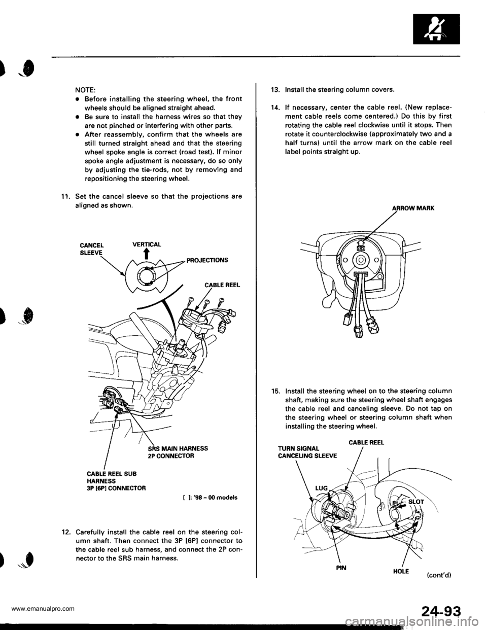
11. Set the cancel sleeve so that the projections are
aligned as shown.
PR(NECNONS
I l: 38 - 00 models
Carefully install the cable reel on the steering col-
umn shaft. Then connect the 3P t6Pl connector to
the cable reel sub harness, and connect the 2P con-
nector to the SRS main harness.
RIC
t
VEAL
)...0
't2.
24-93
13.
14.
Install the steering column covers.
lf necessary, center the cable reel. {New replace-
ment cable reels come centered,l Do this by first
rotating the csble reel clockwise until it stops, Then
rotate it counterclockwise (approximately two and a
half turns) until the arrow mark on the cable reel
label points straight up.
Install the steering wheel on to the steering column
shaft, making sure the steering wheel shaft engages
the cable reel and canceling sl€eve. Do not tap on
the steering wheel or steering column shaft when
installing the steering wheel.
(cont'd)
t5.
CABLE REEL
www.emanualpro.com
Page 1392 of 1395

SRS Unit
).0Replacement
CAUTION:
. Before disconnecting any part of the SRS wire har-
nesg, disconnect the airbag connoctors (and soat beh
tensioner connectorsl.
. During installation or replacament, do not bump(impact wrench, hammer etc.) the area near the SRS
unit.
Do not damage the SFS unit terminalg or connsc-
lors.
Do not disassemble the SRS unit it has no saryice-
able parts,
Store the SRS unit in a clean, dry area.
Do not use any SRS unit which has been subiected
to water damage or shows signs ot being dropped orimproperly handlgd, such as dents, cracks or defor-
mation.
Disconnect the battery negative cable, then discon-
nect the positive cable from the battery, andwaitat
least three minutes.
Disconnect the airbag connectors (and seat belt ten-
sioner connectors). (When disconnected, the airbag
and seat belt tensioner connectors are automatical-
ly shorted.)
Driver's Side:
. Remove the access panel from the steering
wheel, then disconnect the 2P connector
between the driver's airbag and cable reel (see
page 24-231.
Front Passenger's Side:. Disconnect the 2P connector between the frontpassenger's airbag and SRS main harness (see
page 24-231.
Soat Beh Tensionor ('98 - 00 modelsr:. Remove the left and right center pillar lower trimpanels (see section 20).
. Disconnect the seat belt tensioner 2P connectors
from the left side wire harness (driver's side) and
the right wire harness (front passenger's side)(see page 24'231.
2.
a
a
'1.
)
)o
24-95
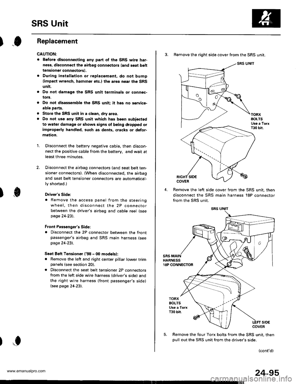
3. Remove the right side cover from the SRS unit.
SRS UNIT
TORXAOLTSUse a TorxT30 bir.
COVER
Remove the left slde cover from the SRS unit. then
disconnect the SRS main harness 18P connector
from the SRS unit.
sRsHARNESS18P CONNECTOR
TORXBOLTSUs€ a TorxT30 bir.
stoECOVER
Remove the four Torx bolts from the SRS unit. then
oull out the SRS unit from the driver's side.
(cont'd)
www.emanualpro.com
Page 1393 of 1395

SRS Unit
Replacement (cont'dl
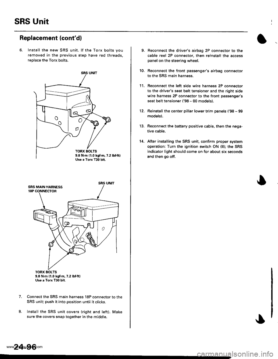
6. lnstall the new SRS unit. lf the Torx bolts you
removed in the previous step have red threads,
replace the Torx bolts.
TORX BOLTS9.8 N.m 11.0 kgf.m,7.2 lbtft)Uso a Torx T30 bit.
Connect the SRS main harness l8P connector to the
SRS uniu push it into position until it clicks.
Install the SRS unit covers (right and left). Make
sure the covers snap together in the middle.
7.
8.
TORX BOLTS9.8 N.m {1.0 kgf.m, ?.2Use . Torx T30 bh,
SRS UNIT
24-96
-
9. Reconnect the driver's aibag 2P connector to the
cable reel 2P connector, then reinstall the access
panel on the steering wheel.
Reconnect the front passenger's airbag connector
to the SRS main harness.
Reconnect the left side wire harness 2P connector
to the driver's seat belt tensioner and the right side
wire harness 2P connector to the front passenger's
seat belt tensioner ('98 - 00 models).
Reinstall the center pillar lower trim panels {'98 - 99
modelsl.
Reconnect the battery positive cable, then the nega-
tive cable.
After installing the SRS unit, confirm proper system
operation: Turn the ignition switch ON (ll); the SRS
indicator light should come on for about six seconds
and then go off,
10.
1't.
12.
13.
14.
www.emanualpro.com