Page 400 of 1395
Intake Air System
Throttle Body (cont'd)
Disassembly
O-RING {A/l only)Replace.
IDLE THERMOVALVE (A/T only)
ADJUSTINGSCREW
9.8 N.m(1.0 kgl.m,7.2 lbf.ftl
The illustration shows'97 - 98models,'99 00 models are similar.
1 1-198
www.emanualpro.com
Page 401 of 1395

Emission Control System
System Description
The emission control system includes, a Three Way
Catalytic Converter {TWC), Positive Crankcase Ventilation
(PCV) svstem and Evaporative Emission (€VAP) Control
system. The emission control system is designed to meet
federal and state emission standards.
Tailpipe Emission
Inspsction
!@ Do not smoke during this procsdura. Keep
any open tlame away from your work area.
1. Start the engine. Hold the engine at 3,000 rpm with
no load (in Park or neutral) until the radiator fan
comes on, then let it idle,
Connect a tachometer.
Check and, if necessary, adjust the idle speed, (see
page 11-169, 170).
Warm up and calibrate the CO meter according to the
meter manufacturer's instructions.
Check idle CO with the headlights, heater blower, rear
window defogger, cooling fan, and air conditioner off.
(Canada) Pull the parking brake lever up. Start the
engine, then check that the headlights are off.
CO meter should indicate 0.1% maximum.
4.
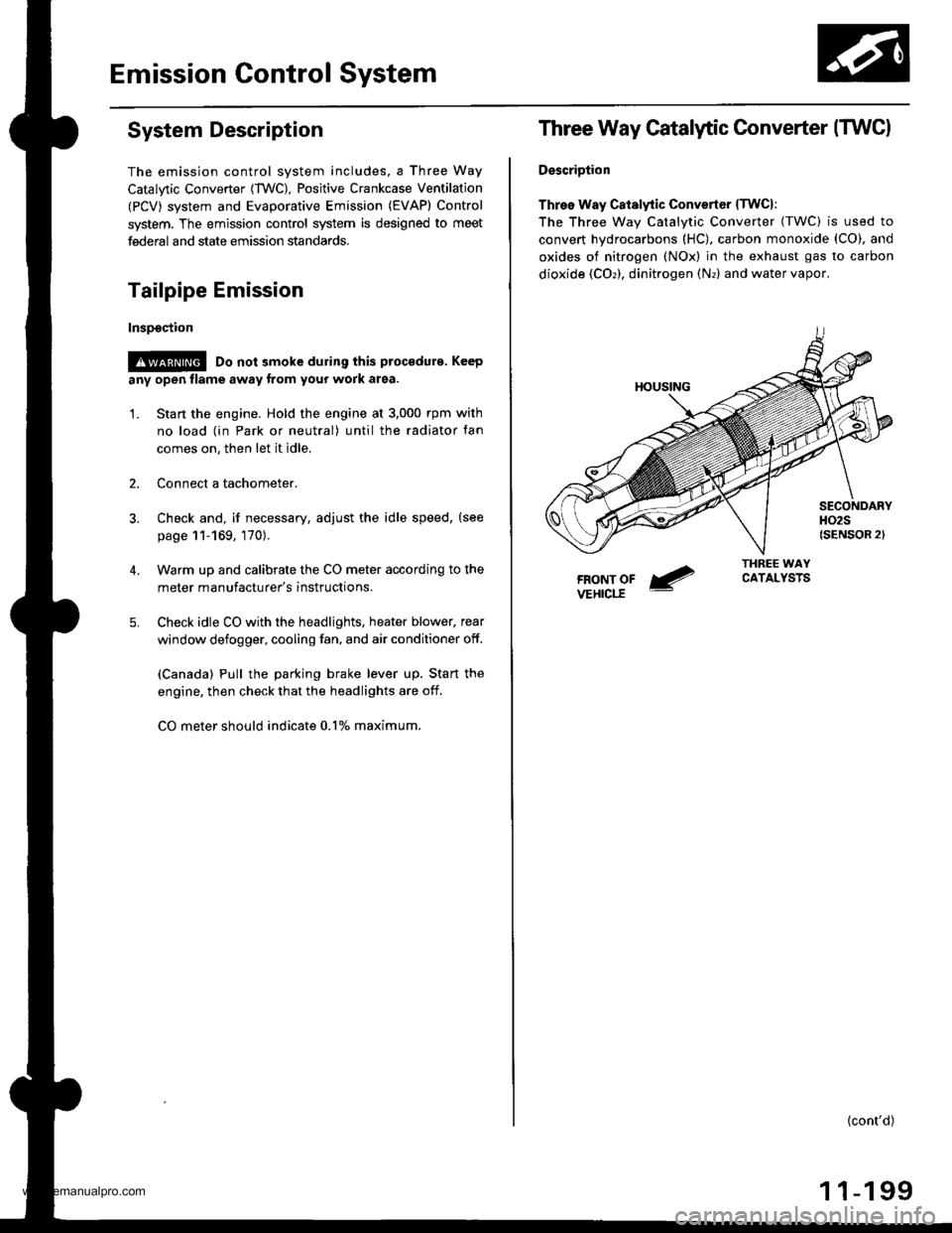
Three Way Catalytic Converter (TWCI
DsscriDtion
Three Way Catalytic Convertsr lTwcl:
The Three wav Catalvtic Converter (TWC) is used to
convert hydrocarbons (HC), carbon monoxide (CO), and
oxides of nitrogen (NOx) in the exhaust gas to carbon
dioxide (COr), dinitrogen (Nr) and water vapor,
{cont'd)
1 1-199
www.emanualpro.com
Page 404 of 1395
Emission Control System
Positive Crankcase Ventilation (PCV) System (cont'dl
2. At idle, make sure there is a clicking sound from the
PCV valve when the hose between the PCV valve
and intake manifold is lightly pinched with your fin-
gers or pliers.
'97 - 98 models:
'99 - 00 modelsi
lf there is no clicking sound, check the PCV valvegrocrmet for cracks or damage, lf the grommet is
OK, reDlace the PCV valve and recheck.
Gently pinch here.
Gently pinch here.
11-202
www.emanualpro.com
Page 451 of 1395

Transmission Assembly
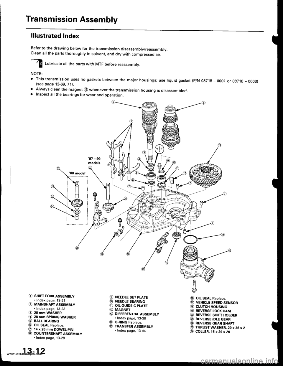
lllustrated Index
Refer to the drawing below for the transmission disassembly/reassembly.Clean all the pans thoroughly in solvent, and drv with comoressed air.
I LuUri""r" utt the parts with MTF before reassembly.
NOTE:
t This transmission uses no gaskets between the major housings; use liquid gasket (p/N 0g718 - 0001 or oE7l8 - 0003)(see page 13-69, 71).. Always clean the magnet @ whenever the transmissjon housing is disassembled.. Inspect all the bearings for wear and operation.
C) sHrFr FoRK ASSEMBLY.Index page, l3-21(a MAINSHAFT ASSEMBLY.Index page, 13-23(9 28 mm WASHER€) 28 mm SPRTNG WASHERO BALL BEARINGa6) OIL SEAL ReDlace.(D 14 x 20 mm DOWEL ptN
G) couNTERSHAFT ASSEMBLY.lndex page, 13-28
NEEDLE SET PLATENEEDLE BEARINGOIL GUIOE C PLATEMAGNETDIFFERENTIAL ASSEMBLY.lndex page, 13-38O-nlNG Beplace.TRANSFER ASSEMBLY.Index page, '13,44
OIL SEAL Replace.VEHICLE SPEED SENSORCLUTCH HOUSINGREVERSE LOCK CAMREVEESE SHIFT HOLDERREVERSE IDLE GEARREVERSE GEAR SHAFTTHRUST WASHER,20 x 36 x 2COLLER, 15 x 20 x 20
aol
@o@@
(D
i9
@@@(9
@@@e3@
13-12
www.emanualpro.com
Page 456 of 1395
20.
2't.
19. Remove the reverse lock cam.
lf necessary, check the clearance of the reverse shift
holder (see page 13-20).
Remove the reverse shift holder.
HOLOER
22. '97 - 99 models: Remove the reverse gear shaft and
the reverse idler gear.'00 model: Remove the reverse gear shaft, reverse
idler gear, thrust washer and the coller.
13-17
23. Remove the mainshaft and countershaft assemblies
with the shift forks from the clutch housing.
NOTE; Before removing the mainshaft and counter-
shaft assemblies, tape the mainshaft spline to pro-
tect it.
ASSEMBLY
Tape the main'
shaft splines.
WASHER
SPRING WASHER
24. Remove the differential asssmbly.
COUNTEBSHAFT
HOUSING
www.emanualpro.com
Page 459 of 1395

Reverse Shift Holder
Clearance Inspection
1.Measure the clearances between the reverse shift
holder and sth/reverse shift Diece Din.
Standard:A: 0.05 - 0.35 mm (0.002 - 0.014 in)
8: 0.4 - 0.8 mm 10.02 - 0.03 inl
Service Limit: A: 0.5 mm (0.02 in)
B: 1.0 mm 10.0,[ in]
2.lf the clearances are more than the service limit.
measure the widths of the groove in the reverse
shift holder.
Standard: A: 7.05 - 7.25 mm {0.278 - 0.285 inl
B: 7.4 - 7.7 mm (0.29 - 0.30 inl
lf the widths of the grooves are not within thestandard, replace the reverse shift holder with a
new one.
lf the widths of the grooves are within the stan-
dard, replace the sth/reverse shift piece with anew one.
PIECE PIN
REVERSE SHIFT HOLDER
13-20
3. Measure the clearance between the reverse idler
gear and reverse shift holder.
Standard: 0.5 - 1.1 mm {0.02 - 0.0i1 in}
Service Limit: 1.8 mm (0.07 in)
REVERSEIDLERGEAR
lf the clearance is more than the service limit. mea-
sure the width ot the reverse shift holder.
Standard: 13.0 - 13.3 mm (0.512-0521inl
It the width is not within the standard, replace
the reverse shift holder with a new one.
lf the width is within the standard, reolace the
reverse idler gear with a new one.
www.emanualpro.com
Page 506 of 1395
Transmission Assembly
Reassembly
1. Install the differential assembly in the clutch hous-
Ing.
Install the spring washer and washer with the angle
against the clutch housing as shown.
Tape the mainshaft splines. insert the mainshaft
and countershaft into the shift forks, and install
them as an assemblv.
Tape the mainshattsplines.
DIFFERENTIAL ASSEMBLY
4. '97 - 99 models: Install the reverse idle gaar and
reverse gear shaft in the clutch
housing.'00 model: Install the coller, thrust washer, reverse
idler gear and the reverse gear shaft in
the clutch housing.
THRUST WASHER
COLLER
NOTE: Install the reverse gear shaft ('00 model) in
the direction shown.
5. Install the reverse shift holder in the clutch housing
with the sth/reverse shift piece pin positioned in the
slot of the reverse shift fork.
5x1.0mm15 N'm 11.5 kgt.m, 11 lbf.ftl
model
REVERSE SHIFT HOLDER
(cont'd)
13-67
www.emanualpro.com
Page 530 of 1395

Description
Power Flow (cont'dl
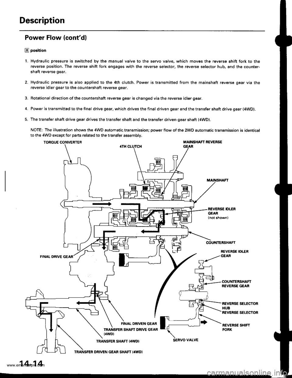
E position
1. Hydraulic pressure is switched by the manual valve to the servo valve, which movss the reverse shift fork to the
reverse position, The reverse shift fork engages with the reverse selector, the reverse selector hub, and the counter-
shaft reverse gear.
2. Hydraulic pressure is also applied to the 4th clutch. Power is transmitted from the mainshaft reverse gear via the
reverse idler gear to the countershaft reverse gear.
3. Rotational direction ofthe countershaft reverse gear ischanged viathe reverse idlergear.
4. Power is transmitted to the final drivegear,which drivesthefinal d riven gear a nd the transfer shaft drive gesr (4WD).
5. The transfer shaft drive gear drives the transfer shaft and the transfer driven gear shaft (4WD).
NOTE: The illustration shows the 4WD automatic.transmission; power flow of the 2wD automatic transmission is identical
to the 4WD except for parts related to the transfer assembly.
TOROUE CONVERTERMAINSHAFT REVERSE
COUNTERSHAFT
FINAL ORIVE
REVERSE IDLERGEAR
COUNTERSHAFTREVERSE GEAR
REVERSE SEITCTORHUBREVERSE SELECTOR
REVEBSC SHIFTFORK
FINAL OBIVEN GEAR
TRANSFER SHAFT DRIVE GEAR{4WD)
TRANSFER SHAFT {4WD)SERVO VAI-VE
14-14
TRANSFER DRIVEN GEAR SHAFT I4WD}
www.emanualpro.com