1997 HONDA CR-V Motor assembly
[x] Cancel search: Motor assemblyPage 41 of 1395

Lubrication Points
For the details of lubrication points and type of lubricants to be applied. refer to the illustrated index and various work pro-
cedures (such as Assembly/Reassembly, Replacement, Overhaul, Installation, etc.) contained in each section.
Recomm6nded Engine OilEngine oil viscosity for ambient temperature ranges
100'F
-30 -20 .10 0 10 20 30 40'c
r1: Always use Genuine Honda Manual Transmission Fluid {MTF). Using motor oil can cause stiffer shifting because it
does not contain the orooer additives.*2: Always use Genuine Honda Premium Formula Automatic Transmission Fluid (ATF). Using a non-Honda ATF can affect
shift qualitv.+3r Always use Genuine Honda DOT 3 Brake Fluid. Using a non-Honda brake fluid can cause corrosion and decrease the
life of the system.*4: Always use Genuine Honda Power Steering Fluid. Using any other type of power steering fluid or automatic transmis-
sion fluid can caused increased wear and poor steering in cold weather.
API SERVICE LABEL
/,.*-G\
/.'z-\e\t/6AE\ll-;-1 5w-30 /---l
w
API CERTIFICATION SEAL
ffi-20 0 20
NO.LUBRICATION POINTSLUBRICANT
EngineAPI Service Grade: Use SJ "Energy Conserving" grade oil. The oilcontainer may also display the API Certitication seal shownbelow. Make sure it says "For Gasoline Engines." SAE vjscosity:See chart below.
2
TransmissionManualGenuine Honda MTF*1
AutomaticGenuine Honda Premium Formula Automatic Transmission Fluid(ATF)*'
3Rear differentialGenuine Honda CVT Fluid
4Brake line (includes ABS line)Genuine Honda DOT 3 Brake Fluid*3
5Clutch LineBrake fluid DOT 3 or DOT 4*3
6Shift lever pivots (Manual transmission)Grease with molybdenum disultide
1Release fork (Manual transmission)LJrea Grease UM264 P/N 4'1211 - PYs - 305
IPower steering gearboxSteering grease P/N 08733 - B070E
Throttle cable end {Dashboard lower panel holelSilicone grease
10l112
14
Throttle cable end (Throttle link)Brake master cylinder pushrodPedal linkageBattery terminalsFuelfill lidClutch master cylinder pushrod
Multi purpose grease
1617181920
Hood hinges and hood lockTailgate hingesHatch glass hingesDoor hinges, upper and lowerDoor opening detent
Honda White Lithium Grease
21
22
Caliper Piston seal, Dust seal,Caliper pin, PistonShilt cable and select cable {Manual transmission)Silicone grease
23Brake line ioints (Front and rear wheelhouse)Rust preventives
24Power steering systemGenuine Honda Power Steering Fluid-.
25Air conditioning compressorCompressor oil: SP 10 lP/N 38897 - P13 - A0lAH or38899-P13-A01)For Refrigerant: HFC 134a (R,134a)
3-2
www.emanualpro.com
Page 192 of 1395

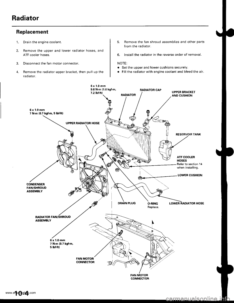
Radiator
1.
2.
3.
4.
Replacement
CONDENSERFAN,/SHROUDASSEMBLY
Drain the engine coolant.
Remove the upper and lower radiator hoses, and
ATF cooler hoses.
Disconnect the fan motor connector.
Remove the radiator upper bracket, then pull up the
raotalor,
5. Remove the fan shroud assemblies and other parts
from the radiator.
6. lnstall the radiator in the reverse order of removal.
NOTE:
. Set the upper and lower cushions securely.
. Fill the radiator with engine cooiant and bleed the air.
RADIATOR CAP
RADIATOR
6x1.0mm9.8 N.m 11.0 kgf.m,7.2 tbl.trl
6x1.0mm7 N.m (0.? kgd.m, 5 lbl.ftl
UPPER MDIATOR HOSE
Reler to section 14when installing.
DRAIN PLUG
LOWER CUSHION
LOWERTOR HOSE
RADIATORASSEMBLY
6x1.0mm7 N.|n 10.7 kgt.m,5 tbt.ftl
rriItriiii
10-4
www.emanualpro.com
Page 511 of 1395

Transmission Assembly
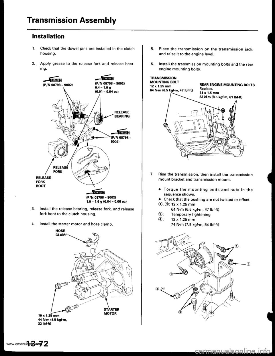
1.
Installation
Check that the dowel pins are installed in the clutch
housing.
Apply grease to the release fork and release bear-
ing.
{P/N 08798 - 90021{P/N 08798 - 9002)0.{ - 1.0 g
{0.0'l - 0.04 ozl
RELEASEBEARING
(P/N 08798 -
9002)
RELEASEFORKBOOT
?
(P/N 08798 - 9002)'1.0 - 1.6 g {0.0,1- 0.06 o2l
Install the release bearing, release fork, and release
fork boot to the clutch housing.
Install the starter motor and hose clamp.
10 x 1.25 mm4{ N'm (4.5 kgf.m,32 tbf.ftl
13-72
HOSE
5. Place the transmission on the transmission jack,
and raise it to the engine level.
6. Install the transmission mounting bolts and the rear
engine mounting bolts.
TRANSMISSIONMOUNTING EOLT12 x 1.25 mn
7.
64 N.m {6.547 tbt.ft)
REAR ENGINE MOUNNNG BOLTSReplace.Itl x 1.5 mm8:l N.m 18.5 kgt m, 61 lbf.ft)
Rise the transmission, then install the transmission
mount bracket and transmission mount.
. Torque the mounting bolts and nuts in thesequence shown.
. Check that the bushing are not twisted or offset.
O. @: 12 x 1.25 mm
64 N.m (6.5 kgf.m, 47 lbf'ft)
O: Temporary tightening
@: 12 x 1.25 mm
74 N.m (7.5 kgf'm,54 lbf.ft)
www.emanualpro.com
Page 672 of 1395

Symptom-to-Com ponent Chart
Hydraulic System (cont'd)
NOTES
See flushing procedure, page l4-264 and 265,
BSet idle rpm in gear to specified idle speed. lf still no good, adjust motor mounts as outlined in enginesection of this manual.
clf the large clutch piston O-ring is broken, inspect the piston groove for rough machining.
Dlf the clutch pack is seized or is excessively worn. inspect the other clutches fot wear, and check the orificecontrol valves, CPC valve, and linear solenoid for free movement.
lf the linear solenoid is stuck, inspect the clutches for wear.
lf the 1-2 shift valve is stuck closed. the transmission will not upshift. lf stuck open, the transmission hasno lst gear.
Hlf the 2nd orifice control valve is stuck, inspect the 2nd and 3rd clutch Dacks for wear.
lf the 3-4 orifice control valve is stuck, inspect the 3rd and 4th clutch packs for wear.
Jlf the clutch pressure control valve is stuck closed. the transmission will not shift out of lst gear.
Klmproper alignment of main valve body and torque converter housing may cause ATF pump seizure. Thesymptoms are mostly an rpm-related ticking noise or a high-pitched squeak.
Llf the ATF strainer is clogged with particles of steel or aluminum, inspect the ATF pump and differentialpinion shaft. lf both are OK and no cause for the contamination is found, replace the torque converter.
Mlf the lst clutch feed pipe guide in the end cover is scored by the mainshaft. inspect the ball bearing forexcessive movement in the transmission housing. lf oK, replace the end cover as it is dented. The o-rinounder the guide is probably worn.
N' Replace the mainshaft if the bushing for the 4th feed pipe is loose or damaged, lf the 4th feed pipe is darrFaged or out of round. replace the end cover.' Replace the mainshaft if the bushing for the l st feed pipe is loose or damaged. lf the 1st feed pipe is dam-aged or out of round, replace it.
oA worn or damaged sprag clutch is mostly a result of shifting the transmission in E!. E, or E positionwhile the wheels rotate in reverse. such as rocking the vehicle in snow.
PInspect the frame for collision damage.
lnspect for damage and wear:
l. Reverse selector gear teeth chamfers.
2. Engagement teeth chamfers of countershaft 4th and reverse gear.
3. Shift fork for scuff marks in center.
4. Differential pinion shaft for wear under pinion gears.
5. Bottom of 3rd clutch for swirl marks.
Replace items 1, 2, 3. and 4 if worn or damaged. lf transmission makes a clicking, grinding, or whirring noise,also replace mainshaft 4th gear, reverse idler gear, and countershaft 4th gear in addition to 1,2, 3, or 4.lf differential pinion shaft is worn, overhaul differential assembly, replace ATF strainer, and thoroughly cjeantransmission, flush torque converter. cooler, and lines,lf bottom of 3rd clutch is swirled and transmission makes gear noise. replace the countershaft and final drivenoear,
Be very careful not to damage the torque converter housing when replacing the main ball bearing. you
may also damage the ATF pump when you torque down the main valve body. This will result in ATF pumpseizure if not detected. Use the Drooer tools.
SInstall the main seal flush with the torque converter housing. lf you push it into the torque converterhousing until it bottoms out, it will block the fluid return passage and result in damage.
www.emanualpro.com
Page 950 of 1395

Component Locations
NOTE: The illustrations show the '97 - 98 models. The '99 - 00 models are similar.
ABS CONTROL UNITRIGHT-REAR WHEEL SENSOR
UNDER.HOOD ABSFUSE/RELAY BOX
RIGHT.FRONT WHEELSENSOR CONNECTOR
RIGHT-FRONTWHEEL SENSORRIGHT-REAB WHEELSENSOR CONNECTOR
MODULATOR UNIT
LEFT.FRONT WHEEL SENSOB
UNDER.DASH FUSE,/RELAY 8OX
UNDER.HOOO FUSE/RELAY AOX
IGl I(, AI FUSE
ABS +B 120 Al FUSEPUMP MOTOR ('II AI FUSE
HOBN/STOP I15 AI FUSE
UNDER.HOOD ABS FUSE/RELAY BOX
LEFT.FRONT WHEELSENSOE CONNECTOR
GAUGE ASSEMBLY
ABS INDICATOR
UNDER-DASH FUSE/NELAY BOX
METER {7.5 AI FUSE
MOTOR RELAY
19-27
SERVICE CHECK CONNECTOR {2PI
D!
trtrtr
[r D!
ABS {7.5 AI FUSEMTR CHECK 17.5 AI FUSE
www.emanualpro.com
Page 955 of 1395
![HONDA CR-V 1997 RD1-RD3 / 1.G Workshop Manual
Circuit Diagram
UNDFS I]OOD FISAFELAY 8OXCbsod: &rrc ped. deprelled
wHT/GrN -tjF GFrlrrvril
GNITION
*oJG\*"\€F*,-
UNDER-HOOD A8S FUSE/FELAY BOX3P CONNECTOR (O number)
t_--t l-|ll"1
UNDER.HOOO A8 HONDA CR-V 1997 RD1-RD3 / 1.G Workshop Manual
Circuit Diagram
UNDFS I]OOD FISAFELAY 8OXCbsod: &rrc ped. deprelled
wHT/GrN -tjF GFrlrrvril
GNITION
*oJG\*"\€F*,-
UNDER-HOOD A8S FUSE/FELAY BOX3P CONNECTOR (O number)
t_--t l-|ll"1
UNDER.HOOO A8](/manual-img/13/5778/w960_5778-954.png)
Circuit Diagram
UNDFS I]OOD FISAFELAY 8OXCbsod: &rrc ped. deprelled
wHT/GrN -tjF GFrlrr'vril
GNITION
*oJG\'*"\€F*,-
UNDER-HOOD A8S FUSE/FELAY BOX3P CONNECTOR (O number)
t_--t l-|ll'"1
UNDER.HOOO A8S FUSE/RELAY BOX2P CONNECTOF (! numbor)
EFIAKE SWITCH CONNECTOR
l€-4| 1 txl2 |
f s a'lLr--'--.----1
UNDER,DASH FUSFJRELAY BOX20P CONNECTOR (O number)M-OD U LATOR UN IT CON N ECTOR
ll3 2ir I
{tT6TsF}
!]q:]j_1,
MP MOTOR CONNECTORnumber)
ATi)
PU
UNDER-DASH FUSE/RELAY BOX18P CONNECTOR (E number)
(tr
ASSEMBLY 5P CONNECTOR
----.4-l1)/l3l/l5l
356J89
10111213,/ 115 ,/19
123456
910'1213|i4 /718
19-32
Wire side ol female lerminals
Terminal side oJ lemale terminals
www.emanualpro.com
Page 1060 of 1395

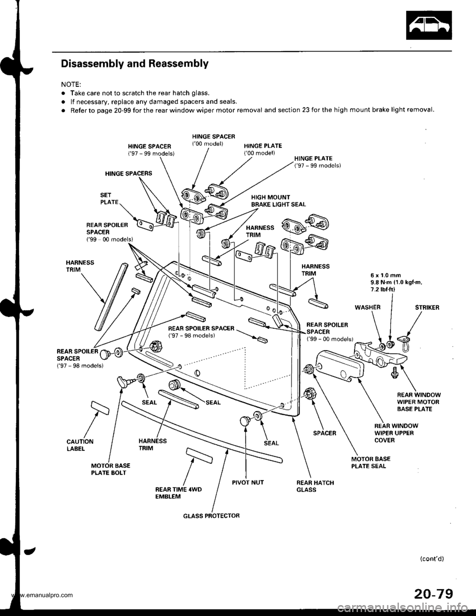
Disassembly and Reassembly
NOTE:
. Take care not to scratch the rear hatch glass.
. lf necessary, replace any damaged spacers and seals.
. Refer to page 20-99forthe rearwindowwiper motor removal and section 23 for the high mount brake light removal.
HINGE SPACERS
HINGE SPACEN('97 - 99 models)HINGE PLATE('00 model)
HARNESSTRIM
REAR SPOILEBSPACER{'99 00 models)
HARNESSTRIM6x1.0mm9.8 N.m {1.0 kgl.m,7.2 tbt.ft)
WASHERSTBIKER
s
R€AF WINDOWWIPER MOTORBASE PLATE
('97 - 98 models)
REAR SPOILERSPACER
CAUTIONLABEL
SEAL
REAR WINDOWWIPER UPPERCOVER
MOTOR BASEPLATE SEAL
PIVOT NUTFEAR TIME 4WDEMBLEM
{cont'd)
20-79
/=
GLASS PROTECTOR
www.emanualpro.com
Page 1079 of 1395

Wiper/Washer
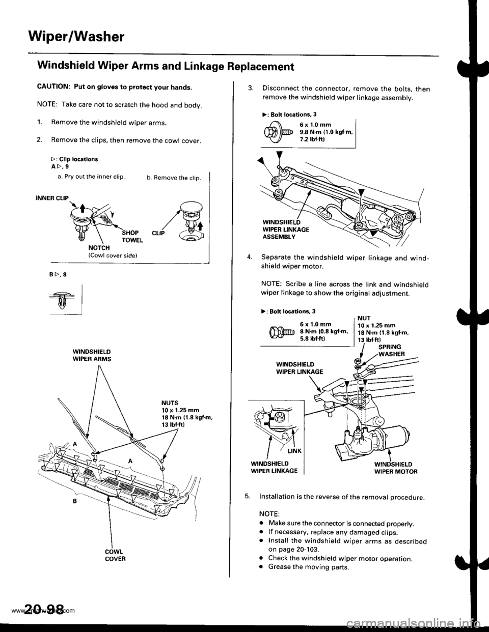
Windshield Wiper Arms and Linkage Replacement
CAUTION: Put on gloves to protoct your hands.
NOTE: Take care not to scratch the hood and body.
1. Remove the windshield wiper arms.
2. Remove the clips, then remove the cowl cover.
>: Clip locationsA>.9
b. Remove the clip.
SHOPTOWEL
(Cowl cover side)
/G
"rr/ &
a. Pry out the anner clip.
INNER CLIP
B>.8
ql
WINDSHIELDWIPER ARMS
NUTS'10 x 1.25 mm18 N.m 11.8 kgf.m.13 tbf.ftl
COVER
20-98
3. Disconnect the connector, remove the bolts, then
remove the windshield wiper linkage assembly.
>: Boh locations,3
4. Separate the windshield wiper linkage and wind-shield wiper motor.
NOTE: Scribe a line across the link and windshieldwiper linkage to show the original adjustment.
>: Boh locations, 3
s}@
1ffi,
/Y{
/
' L|NK
WINDSHIELDWIPER LIN(AGEWIPER MOTOR
5. Installation is the reverse of the removal procedure.
NOTE:
. Make sure the connector is connected properly.. lf necessary. replace any damaged clips.. Install the windshield wiper arms as describedon page 20-103.
. Check the windshield wiper motor operation.. Grease the moving parts.
6x1.0mm9.8 N.m (1.0 kglm,7.2 tbt.fr)
6x1.0mm8 N.m 10.8 kgf.m,5.8 lbf.ftl
NUT10 x 1.25 mm18 N.m 11.8 kgf.m,13 tbf.ftlSPRINGWASHER
www.emanualpro.com