1997 HONDA CR-V Con rod
[x] Cancel search: Con rodPage 194 of 1395
Radiator
Engine Coolant Refilling and Bleeding (cont'dl
Mix the recommended antifreeze with an equal
amount of water in a clean container.
NOTE:
. Always use Genuine Honda Antifreeze/Coolant.
Using a non-Honda coolant can result in corro-s\on, ca
sng t\e coo\
g sys\em \o ma\lunct\on
o. fail.
For best corrosion protection, the coolant con-
centration must be maintained year-round at50% minimum. Coolant concentrations less than
50% may not provide sufficient protection against
corrosion or freezing. Coolant concentrationsgreater than 60% will impair cooling efficiency
and are not recommended.
Do not use additional rust inhibitors or anti-rustproducts; they may not be compatible with the
coolant.
Engine Coolant Refill Capacity Iincluding 0.6 / 10.63US $, 0.53 lmp qtl for hoater and ressrvoirl:
A/T: 3.9 f {4.1 US $, 3.4 lmp qtl
M/T: 1.O t 14.2 US $, 3.5 lmp qrl
10-6
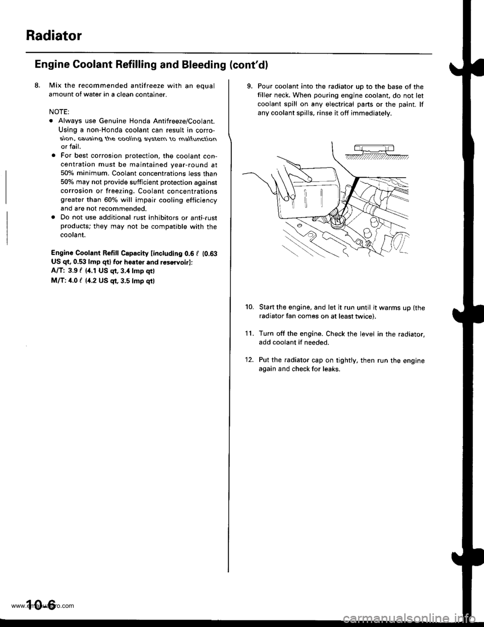
9. Pour coolant into the radiator uD to the base of the
filler neck. When pouring engine coolant. do not let
coolant spill on any electrical pans or the paint. lf
any coolant spills, rinse it oft immediately.
Start the engine, and let it run until it warms up (the
radiator fan comes on at least twice).
Turn off the engine. Check the level in the radiator,
add coolant if needed.
Put the radiator cap on tightly. then run the engine
again and check for leaks.
11.
10.
12.
www.emanualpro.com
Page 307 of 1395

'98 - 00 model3:
The MIL has boon reDortod on.DTC m122 b rtorod.
P.oblom veiification:1. Start the engine. Hold theengine at 3,000 rpm with noload (in Park or neutral) untilthe radiator tan comes on,then turn the ignition switchOFF.2. Turn the ignition switch ON lll).3. Check the throttle position
with the scan tool.
ls there approx. 10% when thethrottle is fully closed andapprox. 90% when the throttleis fully opened?
Intarmittent failure. system is OKat thia time. Check for poor con-n€ctions or loolo wires rt C130ITP s.nsorl and.t the ECM/FCM.
Check for an opon or short in thowire {VCC2 linel:1. Turn the ignition switch OFF.2. Disconnect the TP sensor 3Pconnedor,3. Turn the ignition switch ON (ll).
4. Meas! re voltage betweenthe TP s€nsor 3P connector ter-minals No. 1 and No.3.
ls there approx. 5 V?
Check lor an opon in wiro IVCC2linel:Measure voltage between ECM/rcM connector terminals C'18 andc2a.Chock for en op€n or Bhort in TP3an30r:1. Turn the ignition switch OFF.2. At the sensor side, measureresistance between the TPsensor 3P conneclor terminalsNo. 1 and No. 2 with the throt-tle fully closed.
B.psir opon in the wire b€{woontho ECM/PCM {C281 and th6 TP3en!xtt.ls lher€ approx. 5 V?
Subslitute e known-good ECM/PCM .nd r.chock. lf pro3cribedvoltrge iB now rYrilablo, replacath. originll ECM/PCM.
TP SENSOR 3P CONNECTOR {C130}
sG2IGRN/BLKI
vcc2IYEUBLUI
Wire side oI Iemale lerminals
Wire sid6 of temale terminals
Terminal side of male torminals
(cont'd)
1 1-105
ECM/PCM CONNECTOR C (31P}
sG2IGRN/BLKIa-,l 18 sl./|135
/1617lrs]zolzr zzl
232527)gJ lzgi3o sr I
T^vccz {YEL/8LUl
(To page 11-106)
www.emanualpro.com
Page 314 of 1395
PGM-FI System
'99 - 00 models:
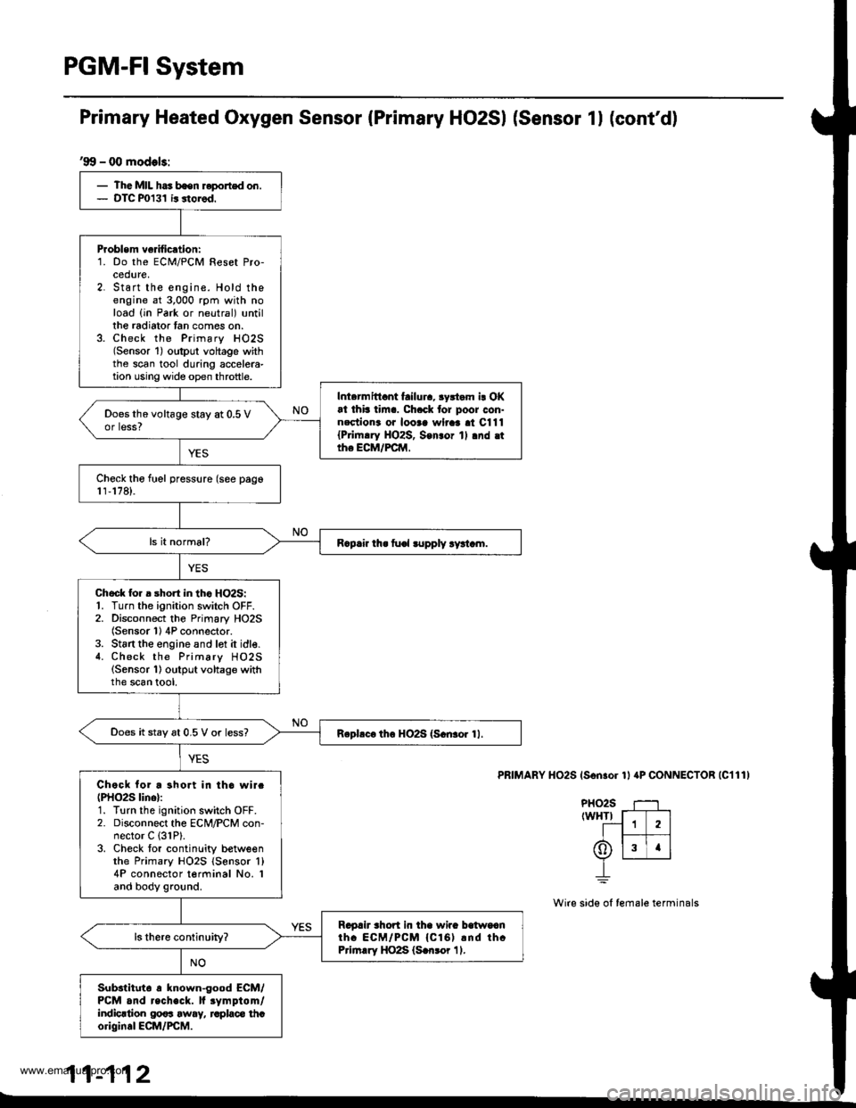
- The MIL has bsen reported on.- DTC P0131 ir storod.
Problem ve fication:1. Do the ECM/PCM Reset Pro-cedure,2. Start the engine. Hold theengine at 3,000 rpm with noload {in Park or neutral) untillhe radiator tan comes on.3. Check the Primary HO2S(Sensor 1) oltput voltage withthe scan tool during accelera-tion using wide op€n throttle.
Inl.rmittant failura, 3yrtam i! OKat thb tim.. Ch.ck tor poor con-nectiona oa looaa wlraa al C111{Pri|n.ry HO2S, Son3or 1l .nd .ttho ECM/FCM,
Does the voltage stay at 0.5 Vor less?
Check tho fuel pressure (see pago1r,178).
R.p.ir th. fu€l lupply ry!t.m.
Chock lor a short in tho HO2S:1. Turn the ignition switch OFF.2. Disconnect the Primary HO2S(Sensor 1) 4P connector.3. St6rt the engine and lot it idle.4. Check the Primary HO2S(Sensor 1) output voltage withthe scan tool,
Does it stay 6t 0.5 V or less?Rephc. th6 HO2S (S.n3or 11.
Chock for a short in tho wirc(PHO2S lino):1. Turn the ignition switch OFF.2. Disconnect the ECM/PCM con-nector C (31P).
3. Check tor continlity betweenthe Primary HO2S {Sensor 'l}
4P connector terminal No. Iand body ground.
Ragah rhort in tha wira balwoanth. ECM/PCM {Cl61 rnd thcPrirn.ry HO2S (S.n3or 11.
Substltut6 a known-good ECM/PCM and recheck. lf rymptom/indicrtion 00os away, raplaco thcoriginal ECM/PCM.
Primary Heated Oxygen Sensor (Primary HO2SI (Sensor 1l (cont'd)
PRIMARY HO2S (Son.or 1l aP CONNECTOR |C111)
PHO2S T--1rwHTr f-T---]
--1 1 2lI t--- 1t6)lslrlv L__r__J
_L
Wire side ol female terminals
11-112
www.emanualpro.com
Page 317 of 1395
'99 - 00 modols:
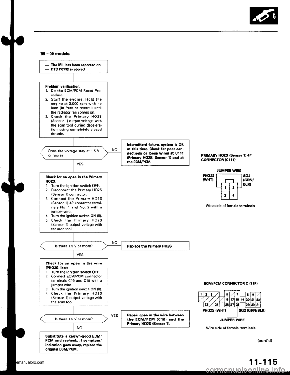
Th6 Mll has b€on reDortod on.DTC ml32 is itorod.
Problem vorification:'1. Do the ECi!4/PCM Reset Procedure,Start the ongine. Hold theengine at 3,000 rpm with noload (in Park or neutral) untilthe radiator fan comes on.Check the Primary HO2SlSensor 1) output voltage withthe scan tool during decelela-tion using completely closedthroftle.
Int.rmitt .fi tailuro, syltom b OKat thit tima. Check for poor con-nactiona oi loo3a wirar !t Cltl(Primrry HO2S, S.nror 1) .nd .tth. ECM/FCM.
Doos the voitage stay at 1.5 Vor more?
Check for an opsn in the PrlmaryHO2S:1. Turn the ignition switch OFF.2. Disconnect the Primary HO2S(Sensor 1)connector.3. Connect the Primary HO2S(Sensor 1) 4P connector t6rmi-nals No. 1 and No. 2 with a
iumperwire.4. Turn the ignition switch ON (ll).
5, Check the Primsry H02S(Sensor 1) output voltage withthe scan tool,
lsthere 1.5 V or more?
Check for an op6n in th6 wiro{PHO2S line):1. Turn tho ignition switch OFF.2. Connect ECM/PCM connectorterminals C16 and C18 with a
iumper wire.3. Turn the ignition switch ON lll).4. Check the Primary HO2S(Sensor 1) output voltage withthe scan tool.
Ropair opon in thc wire bc{w.cnthe ECM/PCM {Cl6}.nd thePrimary HO2S {S€nror 1}.ls there 1.5 V or more?
Substituto a known-good ECM/PCM snd rochock. lf 3ymptom/indicetion go€a awry, roplaca thoorigin.l ECM/PCM.
PRIMARY HOzS (S6n!or 1l aPCoNNECTOR lcltl)
Pt()2sIWHTIsG2{GRN/BTJ(I
Wire side of tem6le terminsls
ECM/PCM CONNECTOR C (31P}
IGRN/BLKI
JUMPER WIRE
Wire side ol temale t6rmin6ls
(cont'd)
-1 15
2789
/1617't819120A22
23E29g)31
PHO2S {WHTIsG2
11
www.emanualpro.com
Page 332 of 1395
PGM-FI System
Knock Sensor {KSl
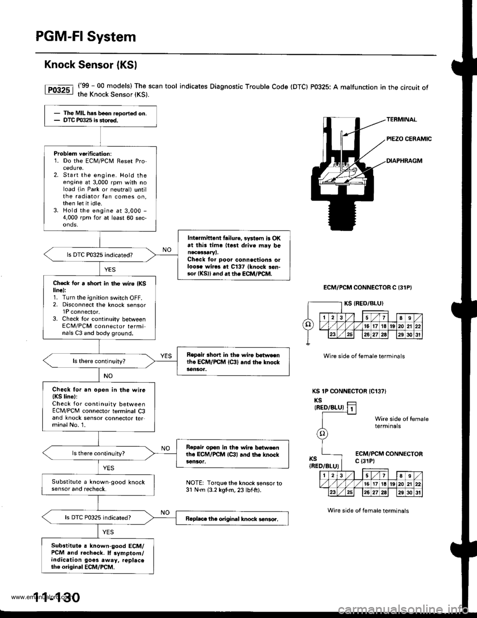
('99 - 00 models) The scan tool indicates Diagnostic Troublo Code (DTC) P0325: A malfunction in the circuit ofthe Knock Sensor (KS).
ECM/PCM CONNECTOR C 131P}
Wire side of female terminals
KS 1P CONNECTOR IC13?'
KSIRED/BLU)
KS(BED/BLU)
Wire side ol femaletermtnals
ECM/PCM CONNECTORc (31P)
- The MIL has been rooorted on.- DTC m325 is storod.
Problem verification:1. Do the ECM/PCir, Reset Procedure,2. Start the engine. Hold theengine at 3,000 rpm with noload (in Park or neutral) untilthe radiator tan comes on,then let it idle.3. Hold the engine at 3,000 -
4,000 rpm for at least 60 sec-onds,
Intermittent lailu.e, 3ystom is OKat thi3 tim. (te3t drive m.y benacalLrYr.Chock to. poor connsctions olloora wiros rt C137 lknock aon-.o. (KS)) and ar the ECM/FCM.
Ch€ck tor a short in the wir6 {KSlinel:1. Turn the ignition switch OFF.2, Disconnect the knock sensorlP connector.3. Check lor continuity betweenECM/PCM connector terminals C3 and body ground.
Replil rhort in the n irg b6{wocntho ECM/PCM lc:ll and the knocks€ngr1.
Check fo..n open in the wire{KS line):Check for continuity betweenECM/PCM connector terminal C3and knock sensor connector ter,minal No. 1.
B.pair opon in the wirc lrotweenlho ECM/PCM lctl and thc knockacnsor.
ls there cont;nuity?
Substitute a known-good knocksensor and recheck.
ls DTC P0325 indicated?Bcpl.ce the original knock 3€nsor,
Substituto a known-good ECM/PCM and .echeck. lf 3ymptom/indication goes away, replacethe original ECM/PCM.
NOTE: Torque the knock s6nsor to31 N.m (3.2 kgl.m, 23 lbf.ft).
1 1-130
Wire side ot female terminals
www.emanualpro.com
Page 338 of 1395
PGM-FI System
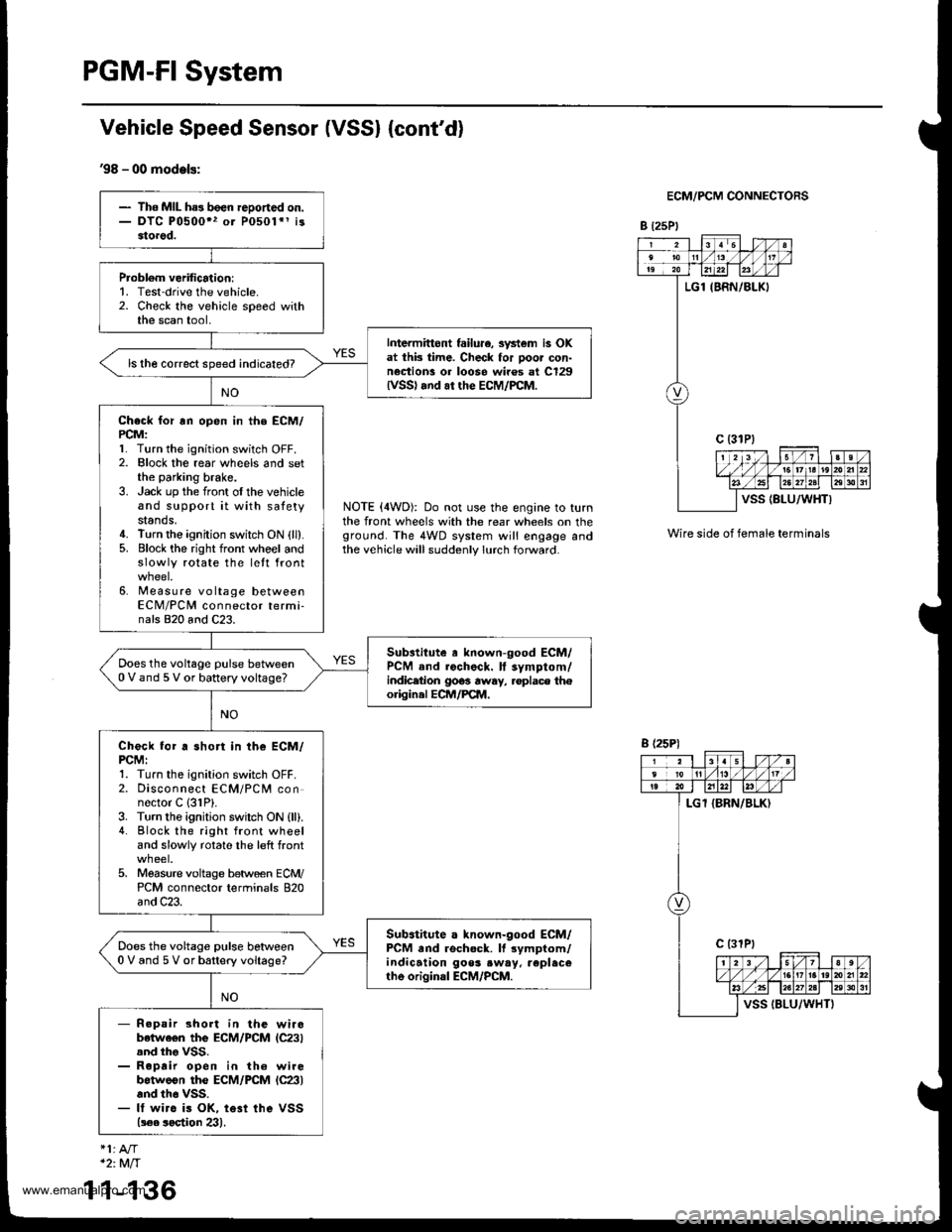
Vehicle Speed Sensor (VSSI {cont'd}
'98 - 00 models:
ECM/PCM CONNECTORS
B t25Pl
NOTE (4WD): Do not use the engine to turnthe front wheels with the rear wheels on theground. The 4WD system will engage andthe vehicle will suddenly lurch forward.
Wire side of female terminals
- The MIL ha3 been reDoned on.- DTC P0500" or P0501*1 i33torod.
Probl6m verification:1. Test-drive the vehicle.2. Check the vehicle speed withthe scan tool,
Intermittont failu.e, svstem is OKat thk time. Check for poor con-nection! or loose wiros at C129lvss) .nd ar the EcM/PcM.
ls the correct speed indicated?
Check for rn open in the ECM/PCM:l� Turn the ignition switch OFF.2. Elock the rear wheels and setthe parking brake.3. Jack up the front oI the vehicleand support it with satetystands.4. Turn the ignition switch ON {ll}.5. Block the right front whoel andslowly rotate the lett front
6. Measure voltage betweenECM/PCM connector termi-nals 820 and C23.
Substitute a known-good ECM/PCM and rochock. ll symptom/indicetion 9063 away, .oplace th€origin.l ECM/PCM.
Does the voltage pulse between0 V and 5 V or battery voltage?
Check for a short in the ECM/PCMI1. Turn the ignition switch OFF.2. Disconnect ECM/PCM connector C 131P).3. Turn the ignition swilch ON {ll).4. Block the right front wheeland slowly rotate the left front
5. Moasure voltage between ECM/PCM connector terminals 820and C23.
Sub.titute a known-good ECM/PCM and rschock. It rymptom/indication goos .w.y. replecerhe original ECM/PCM.
Does the voltage pulse betlveen0 V and 5 V or battery voltage?
- R.pair short in the wirobetwe€n the ECM/PCM lC23).nd tho VSS.- Roprir open in th6 wirebotweon the ECM/PCM lc23land th6 vss.- It wirc is OK, te3t ihe VSS(!€e soetion 23).
B (25P)
1
*2:Mft
1-136
www.emanualpro.com
Page 410 of 1395
Emission Control System
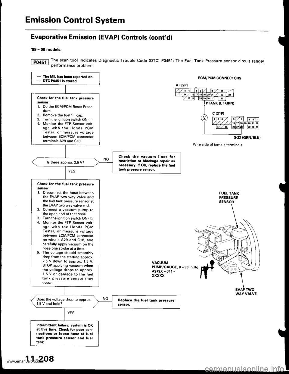
Evaporative Emission (EVAP) Controls (cont'd)
99 - 00 models:
The scan tool indicates Diagnostic Trouble Code {DTC) P0451: The Fuel Tank Pressure sensor circuit range/oerformance Droblem.
ECM/PCM CONNECTORS
SG2 {GRN/BLK)
Wire side of {emaleterminals
FUEL TANKPRESSURESENSOR
VACUUMPUMP/GAUGE.0 -30 in.H9A973X - 041 -
XXXXX
- The MIL har been rooort€d on.- DTC P0451 b storod.
Check lor th6 tu6l tank pr€ssurelen30r:1. Do the ECM/PCM Reset Proce,oure.2. Remove the fuelfill cap.3. Turn the ignition switch ON (ll).4. Monitor the FTP Sensor voltage with the Honda PGMTester, or measure voltagebetween ECM/PCM connectorterminals A29 and C18.
Chock tho vacuum lin6s torrGlriction o. blockago repair asnecessary. lf OK, roplace the fueltank Drer3ur€ sentor.
ls there approx. 2.5 V?
Check for the fuel tank piessureSensot:L Disconnect the hose betweenthe EVAP two way valve andthe fuel tank pressure sensor atthe EVAP two way valve end.2. Connect a vacuum pump tothe open end ofthat hose.3. Turn the ignition switch ON (lll.4. Monitor the FTP S€nsor volt-age with the Honda PGMTester, or measure voltagebetween ECNI/PCNI connectorterminals A29 and C18, andcarefully appiy vacuum on thehose one stroke at a time.5. The voltage should smoothlydrop from the staning approx.2.5 V down to approx. 1.5 V.STOP applying vacuum whenthe voltage drops to approx.1.5 V or damage to the tueltank pressure sensor may
Does the voltage drop to approx.1.5 V and hold?
Intermittent tailuro. sv3tem is OKat this tim€. Chack to. poor con-n€ction6 or 10036 hose at fu6ltank pres3ure ionsor and fueltrnk.
a t32Pl
PTANK ILT GRNI
WAY VALVE
11-208
www.emanualpro.com
Page 421 of 1395

'98 - 00 mod€ls:
The scan tool indicates Diagnostic Trouble code (DTc) P1457: Evaporative Emission (EVAP) Control system leak
detected (EVAP control canister system).
Troubl6shooting Flowchart('98 model only)_]
I
- The MIL has been rePorted on.- DTC P1,157 is storod.
Do the fuel tank Pressure sensor
test {see page 11-214).
ls the {ueltank pressure sensor OK?
Do the EVAP Purge contlol
solenoid valve test lsea Page 1l_
220t.
(cont'dl
11-219
www.emanualpro.com