Page 640 of 1395
Electrical Troubleshooting ('98 - 00 Modelsl
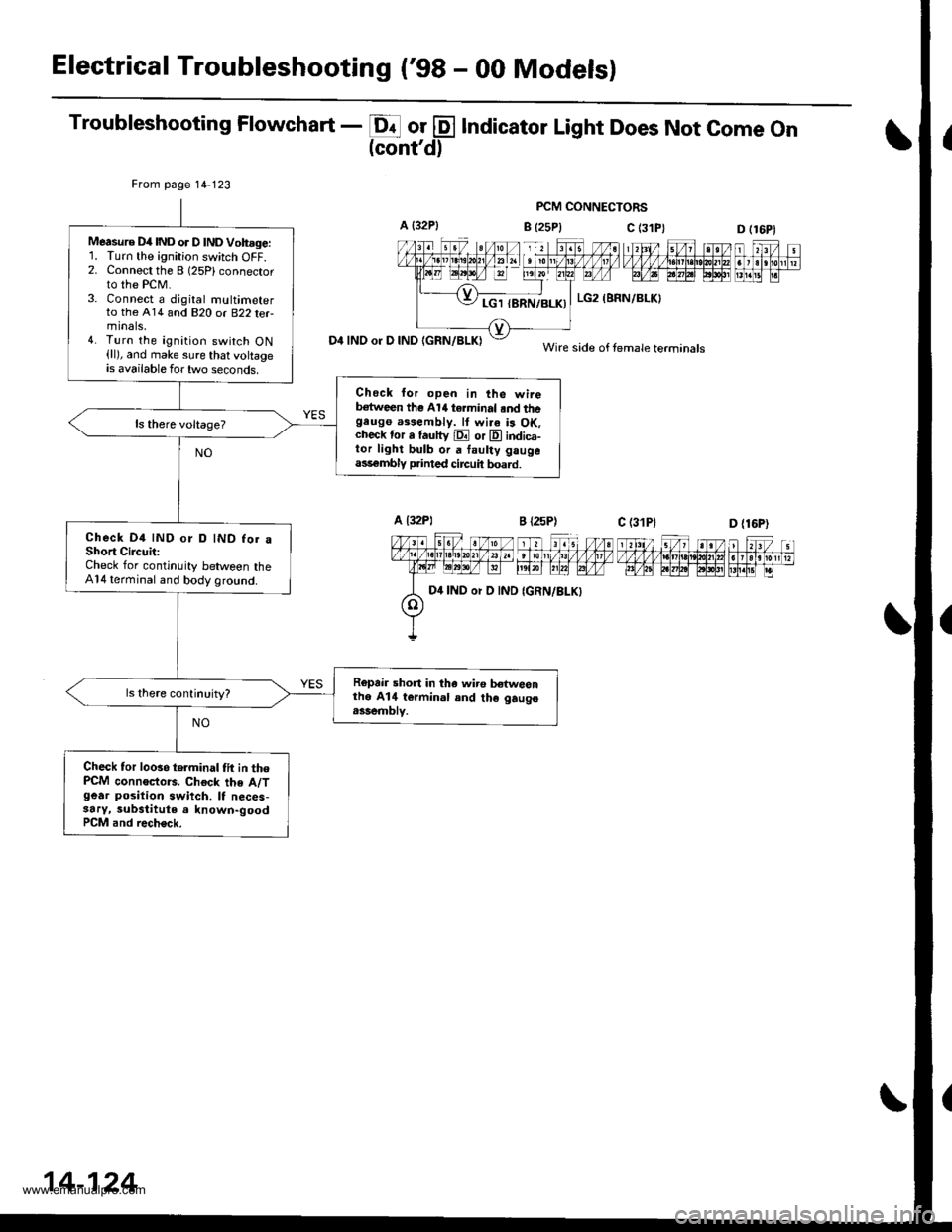
Troubleshooting Flowchart - E or @ Indicator Light Does Not come on(cont'd)
PCM CONNECTORS
B {25P} C (3D (16P1
n f,-ff nt f,Fjrti.trnnmflnr
D4 INO or D IND IGRN/BLKI
From page 14-123
Measure D4IND or D lNDVoh.ge:'L Turn the ignition switch OFF.2. Connect the B (25Plconnector
to the PCM.3. Connect a djgital multimeterto the A14 and 820 or B22 terminals,4. Turn the ignition switch ON(ll), and make sure that voltageis available for two seconds.
Check lor open in the wireb€tween the Al/t terminal .nd thegeugo a$eftbly. lf wi.a is OK.check tor a fautty E or E indica-tor light bulb or a faulty gaugeass€mbly p.inted circuit board.
Check D4 IND or D IND for aShort CircuitiCheck for continuity between theA14 terminal and body ground.
Ropair short in tha wiro b€twesnthe A14 termin.l and th€ gaugo.ssemblv.
Check tor looso telminal tit in thePCM connoctors. Chock the A/Tgear position swiich. It neces-3ary, substitute a known-goodPCM and rech€ck.
c (31P)
LG2 (BRN/BLKI
Wire side of female terminals
D {16P)
D4 IND or D IND
14-124
www.emanualpro.com
Page 641 of 1395
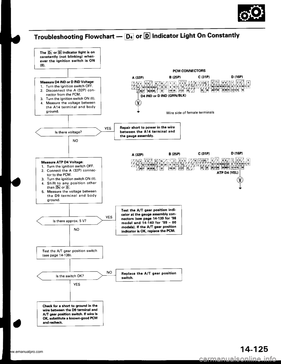
The E or E indicator light is on
constantly (not blinkingl when-
ev€r lhe ignition switch is ON
0.
Me.3rtre D4IND o. D IND Vottage:
1. Turn the ignition switch OFF.
2. Disconnect the A (32P) con-
nector from the PCM.
3. Turn the ignition switch ON (ll)
4. Measure the voltage between
the A14 terminal and bodyground.
Repair short to power in the wire
b€iween th€ A14 terminal and
the gauge a$.mbly.
Measuro ATP D4 voltage:1. Turn the ignition switch OFF2. Connect the A (32P) connec-
tor to the PCM.
3. Turn the ignition switch ON (ll)
4. Shi{t to any position other
than E or E.5. Measure the voltage betweenthe D9 terminal and bodyground.
T6st the A/T g.ar Po3ition indi-
cator at the gauge e$embly con_
nectorc (se€ P.go 1,1-139 lor '98
model .nd 14-140 for '99 - 00
modelsl, f the A/f gear Poshionindicator is OK, replace the FCM.
ls there approx.5 V?
Test the A/T gear position switch(see page 14-139i.
Check for r 3hofi to ground in thewire betweon tho IXI teYminal andA/T gear position switch. lf wire is
OK subBtihrte a known-good PCM
and recheck.
Troubleshooting Flowchart - E or E Indicator Light On Gonstantly
PCM CONNECTORS
B (25P)
11 tr. //at tonl /1! /1/ /llt /
t',lxr uu?l Lrfr4
{GRN/BLKI
D lr6Pl
F't!4[r
Wire side of female terminals
c t3lPl_=---r-:=-t rl3l/ 5/, ?eV t r?V t
t/l,4lzulErt!t!!j!t!u3t ll]]lll1lglt]|b AE A.W6l ld$!'lLM.l1t I r.i
ATP D' (YEL) II
O)
I
A {32P)
D4 IND or D IND
c (3'tP)
A l32Pl
14-125,
www.emanualpro.com
Page 644 of 1395
Electrical Troubleshooting ('98 - 00 Modelsl
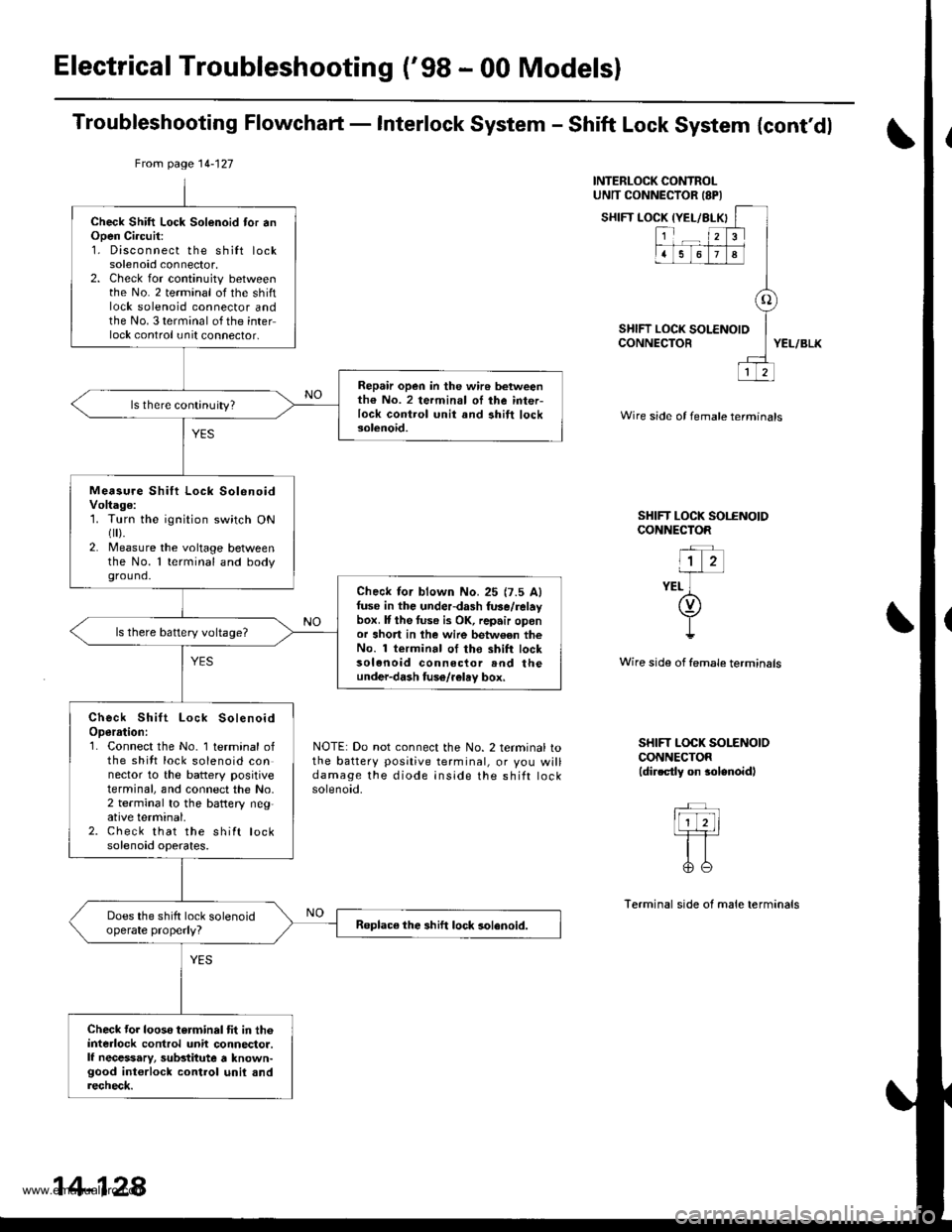
Troubleshooting Flowchaft - Interlock System - Shift Lock System {cont'dl
INTERLOCK CONTROLUNTT CONNECTOR ISPI
SHIFT LOCK IYEL/BLX
SHIFT LOCK tCONNECTOR
{YEL/BLKI
123
1678
o
LOCK SOLENOID
12
YEL/BLK
Wire side of female termtnals
SHIFT LOCK SOI.ENOIDCONNECTOR
"l z-irr-
YEL ](v)
I!
Wire side of female terminsls
NOTE: Do not connect the No. 2 terminal tothe battery positive terminal, or you willdamage the diode inside the shift rocKsolenoid.
SHIFT LOCK SOLENOIOCONNECTOR(dir.ctly on $lenoidl
Terminal side of male terminals
From page 14-127
Check Shift Lock Solenoid tor anOpen Ci.cuit:1. Disconnect the shilt locksolenoid connector,2. Check for continuity betweenthe No. 2 terminal of the shiftlock solenoid connector andthe No. 3 terminal of the interlock control unit connector,
Repair open in the wir6 betweenth€ No. 2 termin.l oI ihe inter-lock control unit and ahift locksolenoid.
ls there continuity?
Measu.e Shift Lock SolenoidVoltage:1. Turn the ignition switch ONflr).2. Measure the voltage betweenthe No. 1 terminal and bodyground.
Check lor blown No.25 {7.5 Alfuse in the underdash fuse/relaybox. It the tuse i3 OK, repair oponor short in lhe wire betw€en theNo. 1 terminal of tho shift locksolenoid connector rnd theunder-dash fuso/r€lay box,
ls there battery voltage?
Check Shift Lock SolenoidOperrtion:1. Connect the No. 1 terminal ofthe shitt lock solenoid connector to the battery positiveterminal, and connect the No,2 terminal to the battery neg,ative terminal.2. Check that the shift locksolenoid operates.
Does the shift lock solenoidoperate properly?Roplace the shift lock solenoid.
Check tor looso torminal tit in th6interlock control unit connector.lf necessary, substitute a known-good int€rlock control unil andrecheck.
14-128
www.emanualpro.com
Page 646 of 1395
Electrical Troubleshooting ('98 - 00 Models)
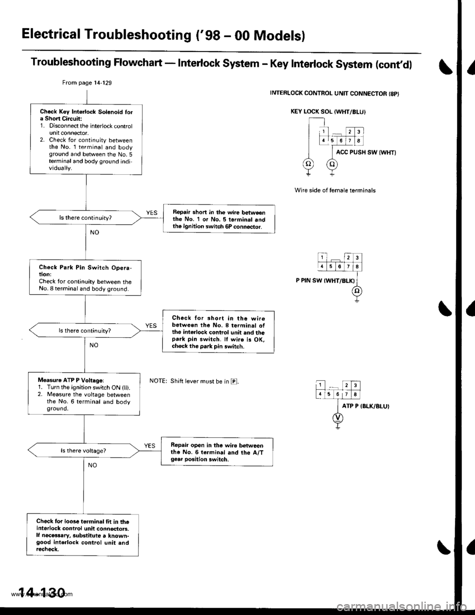
Troubleshooting Flowchart - Interlock System - Key Interlock System (cont,dl
INTERLOCK CONTROL UNIT CONNECTOR {8PI
KEY LOCK SOL (WHT/BI-U}
ACC PUSH SW {WHT)
Wire side of female terminals
ATP P IBLK/BLUI
From page 14'129
Shift lever must be in E.
Check Key Intorlock Solonoid tola Short Circuit:1. Disconnect the interlock controlunit connector,2. Check for continuity betweenthe No. l terminal and bodyground and between the No.5terminal and body ground individually.
Repair shon in thc wire betweonthe No. 1 or No. 5 terminal andth€ ignhion switch 6P connector.
ls there continuity?
Check Park Pin Switch Opera-tion:Check for continuity between theNo. I terminal and body ground.
Check for short in the wir6between the No. 8 terminal ofthe int€rlock control unit and thopark pin switch. ll wire is OK,ch6ck the park pin switch.
ls there continujty?
Moasure ATP P Voftegel1. Turn the ignition switch ON (lli.2. Measure the voltage betweenthe No. 6 terminal and bodyground.
Repair open in the wiro betweenthe No. 6 termin.l and the A/Tgear position 3witch.
Check for looseterminal fit in th€interlock control unit connoctors.lf necosssry, substitute t known-good interlock control unit andrecheck.
14-130
www.emanualpro.com
Page 650 of 1395
Electrical Troubleshooting ('gg - 00 Modelsl
Troubleshooting Flowchart - o/D oFF lndicator Light Does Not come on
Even Though O/D Switch ls pressed (contd)
PCM CONNECTORS
Wire side of female terminals
O/D SW {PNKI
PAFK PIN/O/D SWITCH CONNECTOR
Wire side ot female terminals
From page 14-133
Check O/D Switch Ior a Sho.tCircuit:Check for continuity between theD8 terminal and body ground.
Repair short to ground in thewire betweon the D8 terminaland the park pin/O/D.witchconnectoa,
ls there continuity?
Ch€ck O/D Switch G.ound Cir-cuit:Check lor continuity between theNo. 2 terminal of the switch con-nector and body ground.
Repair opon in the wire b€tweenth€ No. 2 terminal of the parkpinlO/D 3witch connector sndground 1G401. c402), or rep.irpoor ground (G401, 4021.
14-134
www.emanualpro.com
Page 651 of 1395
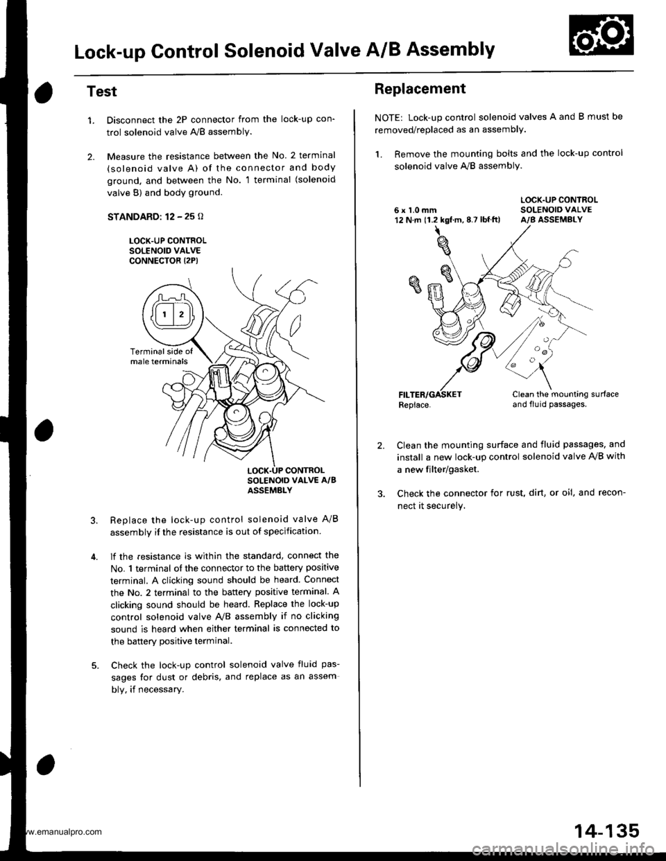
Lock-up Control Solenoid Valve A/B Assembly
Test
1.
2.
Disconnect the 2P connector from the lock-up con'
trol solenoid valve A'lB assembly.
Measure the resistance between the No. 2 terminal
(solenoid valve A) of the connector and body
ground. and bet\iveen the No. 1 terminal (solenoid
valve B) and body ground.
STANDARD: 12 - 25 o
LOCK-UP CONTROLSOLENOID VALVECONNECTOR I2P)
Replace the lock-up control solenoid valve A/B
assembly if the resistance is out of specification
lf the resistance is within the standard, connect the
No. 1 terminal of the connector to the battery positive
terminal. A clicking sound should be heard Connect
the No. 2 terminal to the battery positive terminal. A
clicking sound should be heard. Replace the lock-up
control solenoid valve Ay'B assembly if no clicking
sound is heard when either terminal is connected to
the banerv Dositive terminal.
Check the lock-up control solenoid valve fluid pas-
sages for dust or debris, and replace as an assem
bly, if necessary.
Terminalside ofmale terminals
LOCK.UP CONTROL
Replacement
NOTE: Lock-up control solenoid valves A and B must be
removed/replaced as an assembly.
1. Remove the mounting bolts and the lock-up control
solenoid valve A,,/B assembly.
LOCK.UP CONTROL6 x 1.0 mm SOLENOIO VALVE12 N.m 11.2 kgf.m,8.7 lbf.ft) A/B ASSEMBLY
Replace.Clean the mounting surfaceand flu id passages.
2.Clean the mounting surface and fluid passages, and
install a new lock-up control solenoid valve IVB with
a new filter/gasket.
Check the connector for rust, dirt, or oi!, and recon-
nect it securely.
oa
14-135
www.emanualpro.com
Page 652 of 1395
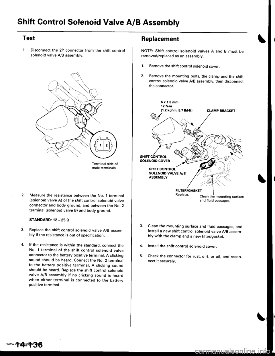
Shift Control Solenoid Valve A/B Assembly
Test
'1. Disconnect the 2P connector from
solenoid valve Ay'B assembly.
the shift control
Terminalsade ofmale terminals
Measure the resistance between the No. 1 terminal(solenoid valve A) of the shift control solenoid valve
connector and body ground, and between the No. 2terminal (solenoid valve B) and body ground.
STANDARD: 12 - 25 O
Replace the shift control solenoid valve A,/B assem-bly if the resistance is out of specification.
lf the resistance is within the standard. connect theNo, I terminal of the shift control solenoid valveconnector to the battery positive terminal. A clickingsound should be heard. Connect the No. 2 terminalto the battery positive te.minal. A clicking soundshould be heard. Replace the shift control solenoidvalve A/B assembly if no clicking sound is heardwhen either terminal is connected to the battervpositive terminal.
14-136
Replacement
NOTE: Shift control solenoid valves A and B must beremoved/replaced as an assembly.
1. Remove the shift control solenoid cover.
2. Remove the mounting bolts, the clamp and the shiftcontrol solenoid valve Ay'B assembly, then disconnect
the connector.
6x1.0mm12 N.m{1.2 k9 .m,8.7 lbtft}CLAMP ARACKET
FILTER/GASKETReplace.Clean the mounling surfaceand fluid passages.
Clean the mounting surface and fluid passages. andinstall a new shift control solenoid valve Ay'B assem-bly with the clamp and a new filter/gasket.
Install the shift control solenoid cover.
Check the connector for rust, dirt. or oil, and recon-nect it securely.
w
SHIFT CONTROLSoLENO|O COVEn
SHIFT CONTROLSOLENOID VALVE A/BASSEMBLY
\--
qK
-!t'">,,
www.emanualpro.com
Page 932 of 1395
![HONDA CR-V 1997 RD1-RD3 / 1.G Workshop Manual
Inspection and Adjustment
Brake System Indicator
Circuit Diagram lNuLR.HorJDGNrT 0llSt!ITCHUNDEB.DASHFUSE]NEtAY BOIrllA Nl] 42 4!A
PAF�K NC BRA(E S\IICH
GBNiBEO
Io\lt j I ERAKE tuU 0 rEVEr 9!1 I(N
| HONDA CR-V 1997 RD1-RD3 / 1.G Workshop Manual
Inspection and Adjustment
Brake System Indicator
Circuit Diagram lNuLR.HorJDGNrT 0llSt!ITCHUNDEB.DASHFUSE]NEtAY BOIrllA Nl] 42 4!A
PAF�K NC BRA(E S\IICH
GBNiBEO
Io\lt j I ERAKE tuU 0 rEVEr 9!1 I(N
|](/manual-img/13/5778/w960_5778-931.png)
Inspection and Adjustment
Brake System Indicator
Circuit Diagram lNuLR.HorJDGNrT 0llSt!ITCHUNDEB.DASHFUSE]NEtAY BOIrllA Nl] 42 4!A
PAF�K NC BRA(E S\I'ICH
GBNiBEO
Io\lt j I ERAKE tuU 0 rEVEr 9!1 I(N
| oPt^r'f,'1 .r
BIKI-o-:G401
Parking Brake Switch Test
1. Remove the parking brake cover,
2. Disconnect the connector from the parking brakeswitch.
3. Check for continuity between the terminal and bodyground in each position according to the table.
Terminal
Lever Position \
Positive
TerminalBody Ground
Lever Up--o
Lever Down
NOTE (Canada): lf the parking brake switch is OK, butthe brake system indicator does not function, perform
the input test for the daytime running lights control unit(see section 23).
Brake Fluid Level Switch Test
1. Remove the reservoir cap. Check that the float
moves up and down freely; if it doesn't, replace the
reservoir cap assembly.
2. Check for continuity between the terminals in each
switch position according to the table.
- r9''r
Position12
FLOAT UP
FLOAT DOWNo
RESERVOIR CAP
GROUND
Switch contacts open atproper fluid level.
19-8
www.emanualpro.com