Page 1370 of 1395

)
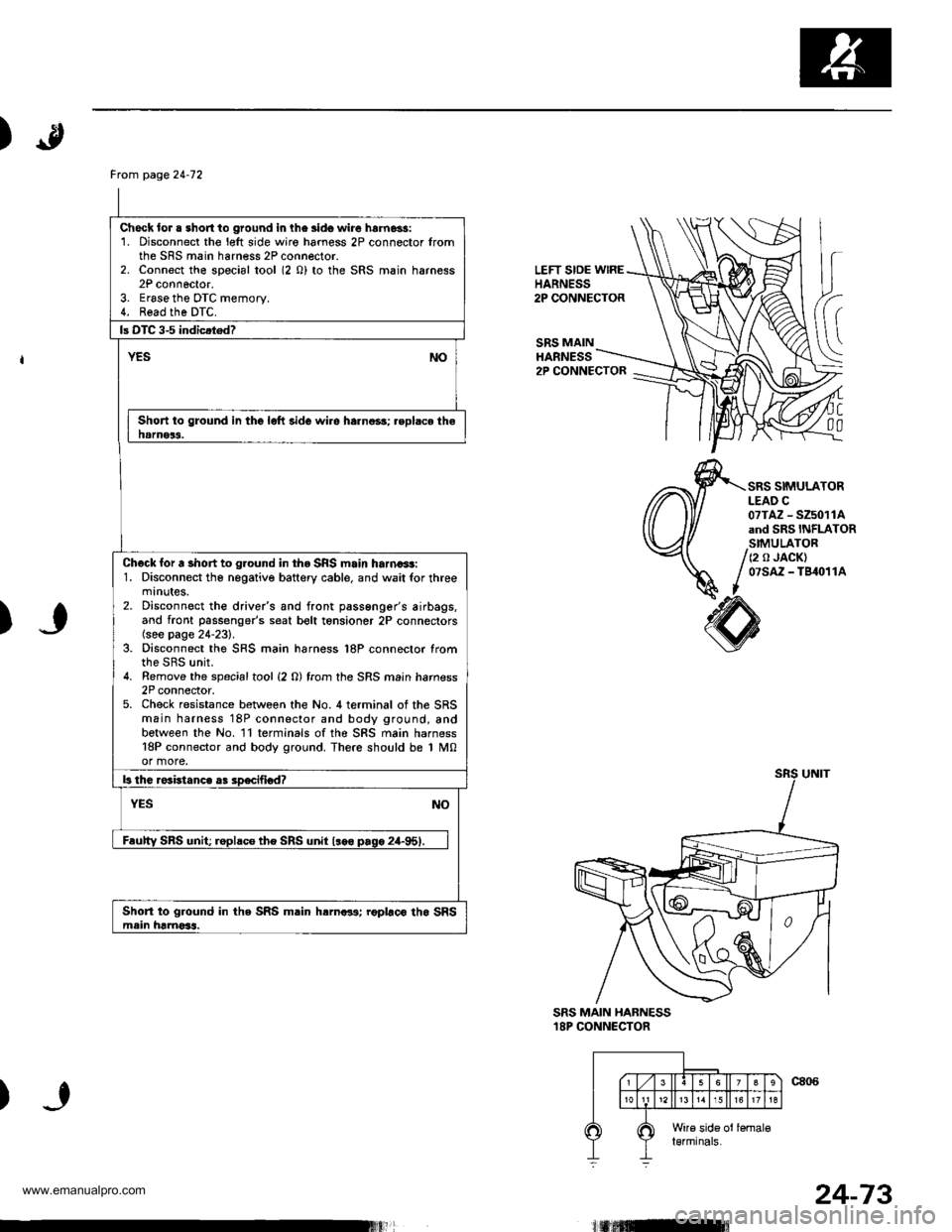
LEFT SIDE wlREHARNESS2P CONNECTOR
SRS MAINHARNESS
(
C
00
2P CONNECTOR
SRS SIMULATORLEAD C07TAZ - SZ5011Aand SRS INFLATORSIMULATOR
/ (2 o JACK)
/ 07sAz - TB4o11A
I
)
SRS MAIN HABNESS18P CONNECTOR
)
Frcm page24-12
Check lor . short to ground in lhe lido wire hrrnassi1. Disconnect the l€lt side wiro hamess 2P connector fromthe SRS main harness 2P connector.2. Connect the special tool (2 0) to the SRS main harness2P connoctor.3. Erase the DTC memory.4. Read the DTC.
Short to ground in the lolt side wi.e harno3s; .eplsce thehamer3.
Check for a short to ground in tho SRS main harna+t:1. Disconnect tho negative battery cable, and wait for threemtnutes.2. Disconnect the drive/s and front passenger's airbags,and front passenger's seat bolt tensioner 2P connectors(see page 24-231.3. Disconnect the SRS main harness l8P connector fromthe SRS unit.4. Remove the spacialtool {2 0) from the SRS main hamess2P connector,5. Check resistance between the No. 4 terminal of the SRSmain harness 18P connector and body ground, andbetween the No. ll terminals ofthe SRS main harness18P connector and body ground. There should be 1 M0or more.
Short to ground in the SRS m.in hrrnar3; roplaco tho SRSmein hamoSs.
24-73
www.emanualpro.com
Page 1376 of 1395

)
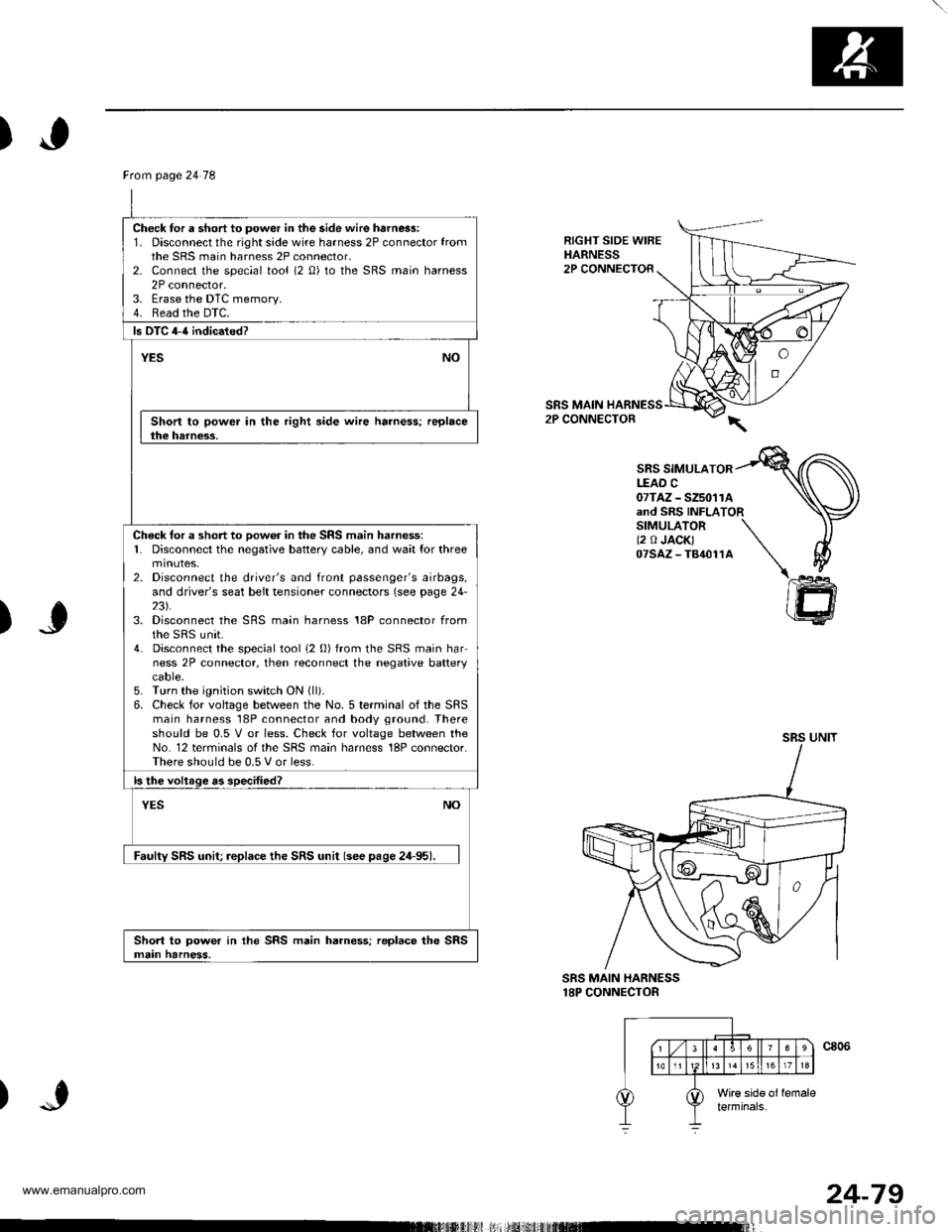
RIGHT SIDE WIREHARNESS2P CONNECTOR
SRS MAIN2P CONNECTOR
SBS SIMULATORLEAD C07TAZ - SZ5011Aand SRS INFLATORSIMULATOR \(2 0 JACK) \07sAz-T84011A \\
)J
)
@
SRS MAIN HARNESS18P CONNECTOR
Ftom page 24 78
Check for a short to power in the side wire harn6s:1. Disconnect the right side wire harness 2P connector fromthe SRS main harness 2P connector,2- Connect the special tool (2 0) to the SRS main harness2P connector.3. Erase the DTC memory.4. Read the DTC.
ls DTC 4-{ indicated?
YESNO
Short to power in the right side wire harness; replacethe harness.
Check tor a short to oow6r in the SRS main harness:1. Disconnect the negative battery cable, and wait for threemtnutes,2. Disconnect the driver's and front passenger's airbags,and driver's seat belt tensioner connectors (see page 24-23).3. Disconnect the SRS main harness 18P connector fromthe sRS unit.4. Disconnect the special tool i2 0) from the SRS main harness 2P connector, then reconnect the negative batterycaore.5. Turn the ignition switch ON (ll).
6. Check for voltage between the No. 5 terminal of the SRSmain harness 18P connector and body ground. Thereshould be 0.5 V or less. Check for voltage between theNo. 12 terminals of the SRS main harness 18P connector.There should be 0.5 V or less.
ls the voltage as specified?
NOYES
Faulty SRS unit; replace the SRS unit (see pase 24-95).
Short to power in the SRS main harness; replace the SRSmain harness.
24-79
www.emanualpro.com
Page 1378 of 1395

From page 24'80
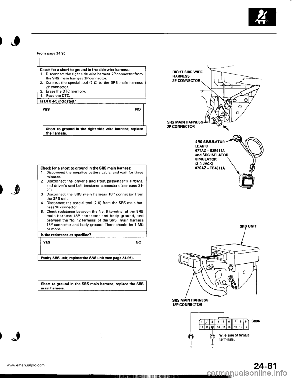
Check lor a short to ground in the sido wir€ harness:1. Disconnect the rightsidewire harness 2P connector fromthe SRS main harness 2P connector.2. Connect the special tool {2 O) to the SRS main harness2P connector.3. Erase the DTC memorv.4. Read the DTC.
b DTC 4-5 indicrtad?
YESNO
Short to ground in the right side wire harness; replac.the harne3!.
Check tor a short io ground in the SRS main ha.nessi1. Disconnect the negative battery cable, and wait for threeminotes,2. Disconnect the driver's and front passenger's airbags,and driver's seat belt tonsioner connectors (see page 24-231.3. Disconnect the SRS main harness 18P connector from
4. Disconnect the special tool (2 0) from the SRS main har-ness 2P connector.5. Check resistance between the No. 5 terminal oI the SRSmain harness 18P connector and body ground, andbetween the No. 12 terminal of the SRS main harness18P connector and body ground. There should be 1 M0or more,
b th€ re3i3tance as specified?
NOYES
Faulty SRS unit replace the SRS unit {see pace 2a-951.
Short to ground in the SRS main harness; replace the SRSmain harnoss.
RIGHT SIDE WIREHARNESS2P CONNECTOR
SRS MAIN HARNESS2P CONNECTOR
SRS SIMULATORLEAD C07TAz - SZ5011Aand SRS INFLATORSIMULATOR \{2 0 JACK} \07SAZ-TB,O114 \I
ffi
)
SRS MAIN HANNESS18P CONNECTOR
24-81
www.emanualpro.com