Page 1251 of 1395
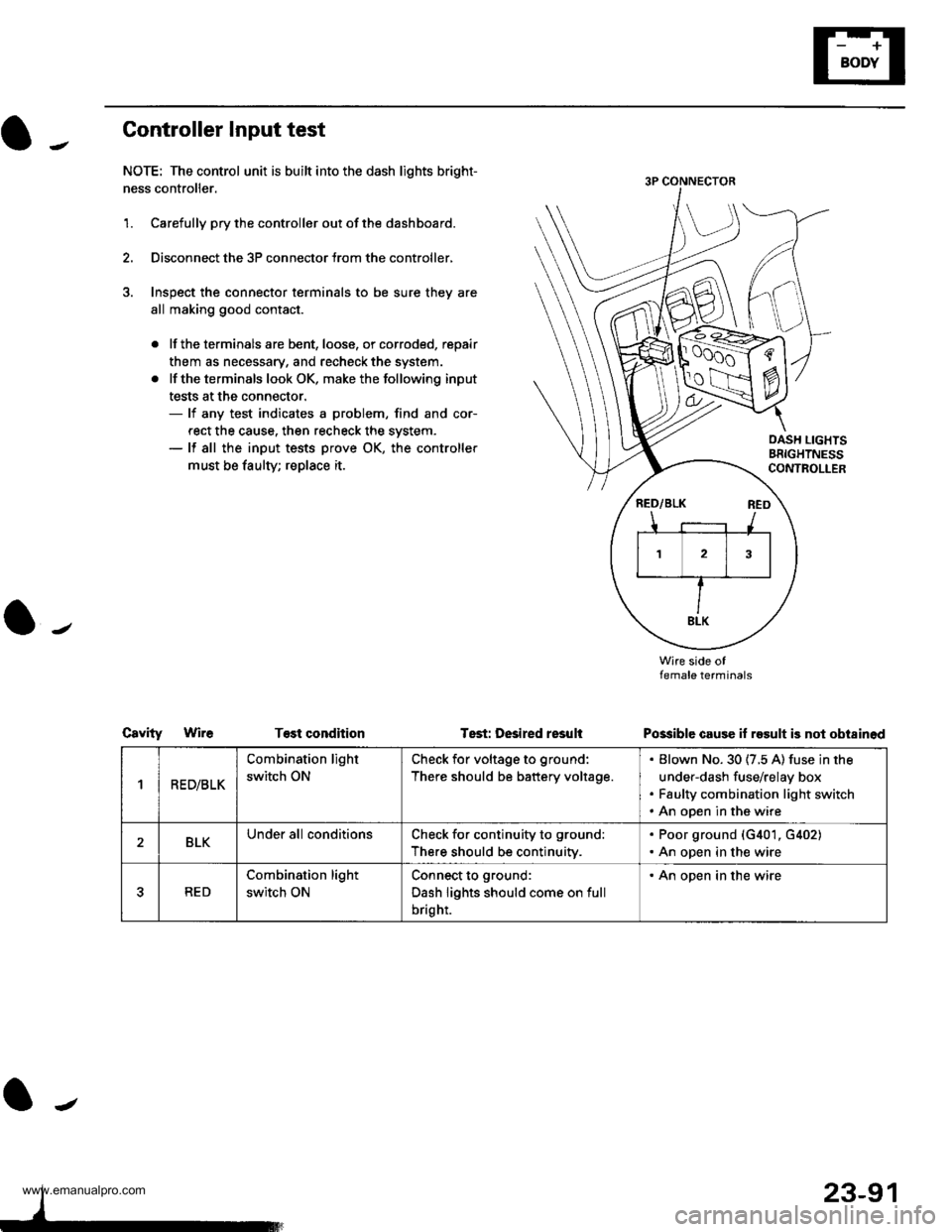
Controller Input test
NOTE: The control unit is built into the dash lights bright-
ness controller.
1.Carefully pry the controller out of the dashboard.
Disconnect the 3P connector trom the controller,
Inspect the connector terminals to be sure they are
all making good contact.
. lf the terminals are bent, loose, or corroded, repair
them as necessary, and recheck the system.
. lf the terminals look OK, make the following input
tests at the connector.- lf any test indicates a problem, find and cor-
rect the cause. then recheck the system.- lf all the input tests prove OK, the controller
must be taulty; replace it.
CsvityWireT€st condhion
Wire side oflemale terminals
Possible cause if result is not obi8inod
OASH LIGHTSBRIGHTNESSCONTROLLER
Tsst: Desired resuli
1R ED/BLK
Combination light
switch ON
Check for voltage to ground:
There should be battery voltage.
Blown No. 30 (7.5 A) fuse in the
under-dash fuse/relay box
Faulty combination light switch
An open in the wire
2BLKUnder all conditionsCheck for continuity to ground:
There should be continuitv.
. Poor ground (G401, G402). An open in the wire
5RED
Combination light
switch ON
Connect to ground:
Dash lights should come on full
bright.
. An open in the wire
23-91
www.emanualpro.com
Page 1256 of 1395
Accessory Socket
Accessory Socket Test/Replacement
Front Accessory Socket:
1. Remove the center dashboard lower cover (see sec-
tion 20).
Disconnect the 2P connector from the front accessory
socket.
Inspect the connector terminals to be sure they are
all making good contact.
2.
lf the terminals are bent, loose or corroded, repair
them as necessary, and recheck the system.
lf the terminals look OK, go to step 4.
ACCESSORYSOCKET
Turn the ignition switch to ACC (l), and check for
voltage between the No. 1 and No. 2 terminals.
. There should be battery voltage.
. lf there is no battery voltage, check for:- blown No.27 (10 A) fuse in the under-dash
fuse/relay box.- poor ground (G401, G402).- an open in the wire.
23-96
5. If all the tests prove OK, replace the front accessory
socket.
PBOTECTOB
FACE PANEL
www.emanualpro.com
Page 1257 of 1395
Rear Accessory Socket:
'1. Remove the left rear side trim panel {see section
20t.
2.Disconnect the connectors.
lnspect the connector terminals to be sure they are
all making good contact.
lf the terminals are bent, loose or corroded,
repair them as necessary, and recheck the sys
tem.
. lf theterminals look OK, goto step 4.
ACCESSORYSOCKET
A (YEL/8LUI
3.
\J
ryIIBLK}
4. Turn the ignition switch to ACC (l), and check tor volt
age between the A and B terminals.
o There should be battery voltage.
. lf there is no battery voltage, check for:- blown No. 6 ('10 A) and No. 27 (10 A) fuses in
the under dash fuse/relay box.- faulty rear accessory socket relay (test, page
23-53).- poor ground (G401, G402, G553).- an open in the wire.J
23-97
5. Remove the thermofuse housing and thermal pro
tector, then remove the socket and cover.
THEEMALPROTECTOR
T$THERMOFUSEHOUSING
COVER
SOCKET
www.emanualpro.com
Page 1266 of 1395
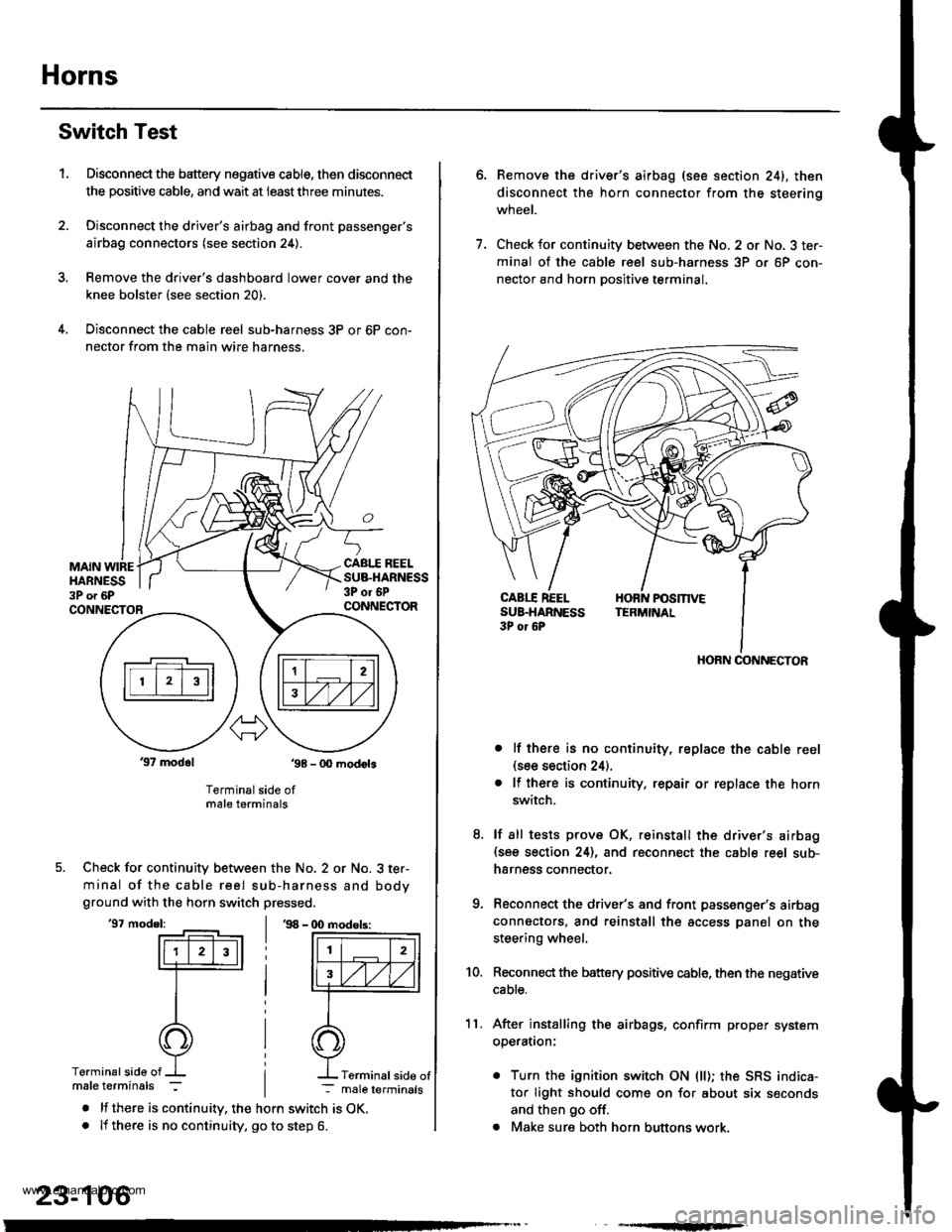
Horns
Switch Test
Disconnect the battery negative cable, then disconnect
the positive cable, and wait at ieastthree minutes.
Disconnect the driver's airbag and front passenger's
airbag connectors (see section 24).
Remove the drive.'s dashboard lower cover and the
knee bolster (see section 20).
Disconnect the cable reel sub-harness 3P or 6P con-
nector from the main wire harness.
1.
MAIN WIREHARNESS3P o. 6P
CABI.I REELSUB.HARNESS3P or 6PCONNECTORCONNECTOR
37 modol ,98 - 0O modots
Terminal side ofmale terminals
Check for continuity between the No. 2 or No. 3 ter-
minal of the cable reel sub-harness and bodyground with the horn switch pressed.
'97 model:'98 - (X) modols:
Terminalside of
. lf there is continuity. the horn switch is OK.. lf there is no continuity, go to step 6.
23-106
Terminal side of
6.Remove the driver's airbag (see section 241, then
disconnect the horn connector from the steerinq
wneet.
Check for continuity between the No. 2 or No. 3 ter-
minal of the cable reel sub-harness 3P or 6P con-
nector and horn Dositive terminal.
lf there is no continuity, replace the cable reel(see section 24).
lf there is continuity. repair or replace the horn
switch.
lf sll tests prove OK, reinstall the driver's airbag(see section 24), and reconnect the cable reel sub-
harness connector.
Reconnect the driver's and front passenger's airbag
connectors, and reinstall the access panel on the
steering wheel.
Reconnect the battery positive cable, then the negative
cable.
After installing the airbags, confirm proper system
operatron:
. Turn the ignition switch ON (ll); the SRS indica-
tor light should come on for about six seconds
and then go off.
. Make sure both horn buttons work.
7.
11.
8.
9.
10.
HORN CONNECTOR
www.emanualpro.com
Page 1273 of 1395
Switch Input Test
NOTE: Before testing, check for blown No. 17 (7.5 A)
fuse in the under-dash fuse/relay box.
1. Remove the center panel {see section 20).
REAR WINOOW DEFOGGER SWITCHlin the heater control oanel)CENTER PANEL
Check for voltage between the 84 and 87 terminals
in each switch position when battery power is con-
nected to the B l terminal.
OFFless than 0.4 V
ONbaftery voltage
Ol-
I
-
23-113
www.emanualpro.com
Page 1278 of 1395
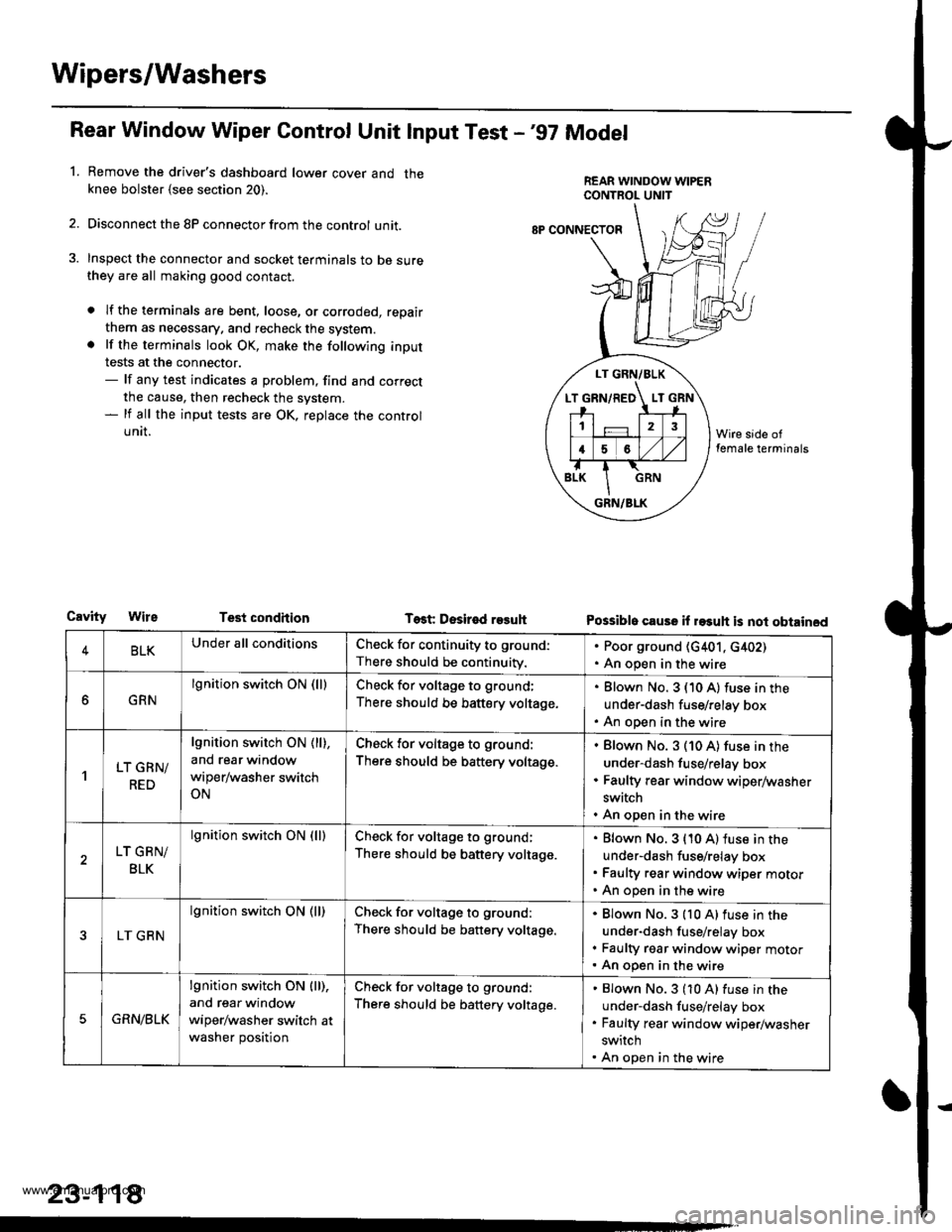
Wipers/Washers
Rear Window Wiper Gontrol Unit lnput Test -'97 Model
Remove the driver's dashboard lower cover and theknee bolster {see section 20).
Disconnect the 8P connector from the control unit.
Inspect the connector and socket terminals to be surethey are all making good contact.
a lf the terminals are bent, loose, or corroded, repair
them as necessary. and recheck the system.. lf the terminals look OK, make the following input
tests at the connector.- lf any test indicates a problem, find and correct
the cause, then recheck the system.- lf all the input tests are OK, replace the control
UNII.
1.
LT GRN/BLK
T GRN/RED LT
12
16
GRN/BLK
8P CONNECTOF
CavityTest condhion Test Desir€d r93uhPossible cause il rasuh is not obtained
4BLKUnder all conditionsCheck for continuity to ground:
There should be continuity.
. Poor ground (G401, c402). An open in the wire
GRN
lgnition switch ON (lllCheck for voltage to ground;
There should be battery voltage.
Blown No. 3 (10 A) fuse in the
under-dash fuse/relay box
An open in the wire
'lLT GRN/
RED
lgnition switch ON ( ll),
and rear window
wiper/washer switch
ON
Check for voltage to ground:
There should be battery voltage.
Blown No. 3 (10 A) fuse in the
under-dash fuse/relay box
Faulty rear window wiper/washer
switch
An open in the wire
LT GRN/
BLK
lgnition switch ON (lllCheck for voltage to ground;
There should be battery voltage.
Blown No. 3 {10 A) fuse in the
under-dash fuse/relay box
Faulty rear window wiper motor
An open in the wire
LT GRN
lgnition switch ON (ll)Check for voltage to ground:
There should be battery voltage.
Blown No.3 {10 A)fuse in the
under-dash fuse/relay box
Faulty rgar window wiper motorAn open in the wire
5GRN/BLK
lgnition switch ON lll),
and rear window
wiper/washer switch at
washer position
Check for voltage to ground:
There should be battery voltage.
Blown No.3 (10 A) fuse in the
under-dash fuse/relay box
Faulty rear window wiper/washer
switch
An open in the wire
23-118
www.emanualpro.com
Page 1279 of 1395
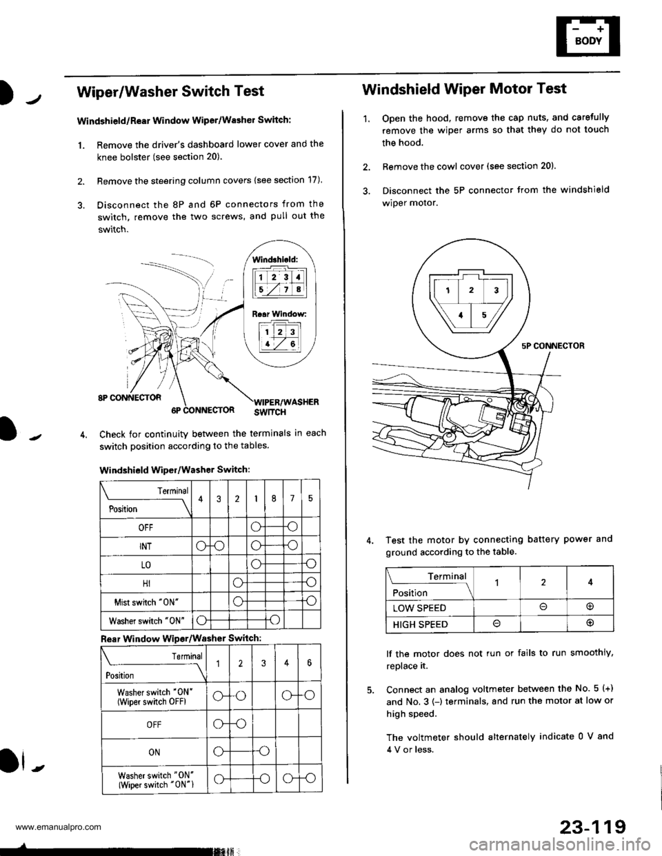
Wiper/Washer Switch Test
Windshield/ReEr Window Wiper/Washer Switch:
1. Remove the driver's dashboard lower cover and the
knee bolster (see section 20).
2. Remove the steering column covers {see section 17)
3. Disconnect the 8P and 6P connectors from the
switch, remove the two screws, and pull out the
switch.
J-
lind3hi.ld:
tilt-rltl
IEZIA
Raar Window:
11 2 3
I t-7 al
ll -
Check for continuity betlveen the termlnals in each
switch position according to the tables.
Windshield Wiper/Washer Switch:
Terminal
P*t-
---__\432175
OFFoo
INToooo
LOoo
HIoo
Mist swhch "0N"oo
Washer switch "0N"oo
Rear Window Wipsr/Washer Switch
Teminal
ti'"
---\12346
Washer switch '0N'
(wiper switch oFFlG-oG-o
OFFG-o
ONGo
Washer switch "ON'
(Wiper switch "0N"1G-oG-o
-rmxft
23-119
1.
Windshield Wiper Motor Test
Open the hood, remove the cap nuts, and caretully
remove the wiper arms so that they do not touch
the hood.
Remove the cowl cover (see section 201.
Disconnect the 5P connector trom the windshield
wiper motor.
Test the motor by connecting battery power and
ground according to the table.
lf the motor does not tun or fails to run smoothly,
replace it.
Connect an analog voltmeter between the No. 5 (+)
and No. 3 (-) terminals, and run the motor at low or
high speed.
The voltmeter should alternately indicate 0 V 8nd
4 V or less.
Terminal
;fi;"
-l4
LOW SPEED@
HIGH SPEED@
www.emanualpro.com
Page 1280 of 1395
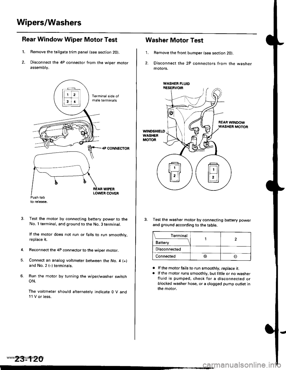
Wipers/Washers
1.
Rear Window Wiper Motor Test
Remove the tailgate trim panel (see section 20),
Disconnect the 4P connector from the wiper motor
assembly.
4P CONNECTOR
WIPEBLOWER COVEnPush tabto release,
Test the motor by connecting battery power to theNo. I terminal, and ground to the No. 3 terminal.
lf the motor does not run or fails to run smoothly,replace it.
Reconnect the 4P connector to the wiper motor.
Connect an analog voltmeter between the No. 4 (+)
and No. 2 (-) terminals.
Run the motor by turning the wiper/washer switchoN.
The voltmeter should alternately indicate 0 V and11 V or less.
4.
5.
23-120
1.
Washer Motor Test
Remove the front bumper (see section 20).
Disconnect the 2P connectors from the washermolors,
REAR WINDOWWASHER MOTOR
Test the washer motor by connecting battery power
and ground according to the table.
lf the motor fails to run smoothly, replace it.lf the motor runs smoothly, but little or no washerfluid is pumped, check for a disconnected orblocked washer hose, or a clogged pump outlet inthe motor.
a
a
L_Iq'.r91
Battery
,l
Disconnected
Connected@
www.emanualpro.com