1997 HONDA CR-V battery terminals
[x] Cancel search: battery terminalsPage 1288 of 1395
Power Door Locks
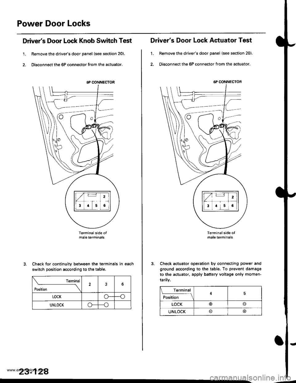
Driver's Door Lock Knob Switch Test
1. Remove the driver's door panel (see section 20).
2. Disconnect the 6P connector from the actuator.
Terminalside otmale terfiinals
Check for continuity between the terminals in each
switch position according to the table.
rsrmrnal
Position \
?6
LOCKo--o
UNLOCKo---o
23-128
.
6P CONNECTOR
Driver's Door Lock Actuator Test
1, Remove the driver's door panel (see section 20).
2. Disconnect the 6P connector from the actuator.
Terminal side ofmale terminals
Check actuator operation by connecting power and
ground according to the table. To prevent damsge
to the actuator. apply battery voltage only momen-
tarilv,
6P CONNECTOR
Terminal
F*'',1."
__l
LOCK@o
UNLOCK@
'-
www.emanualpro.com
Page 1289 of 1395
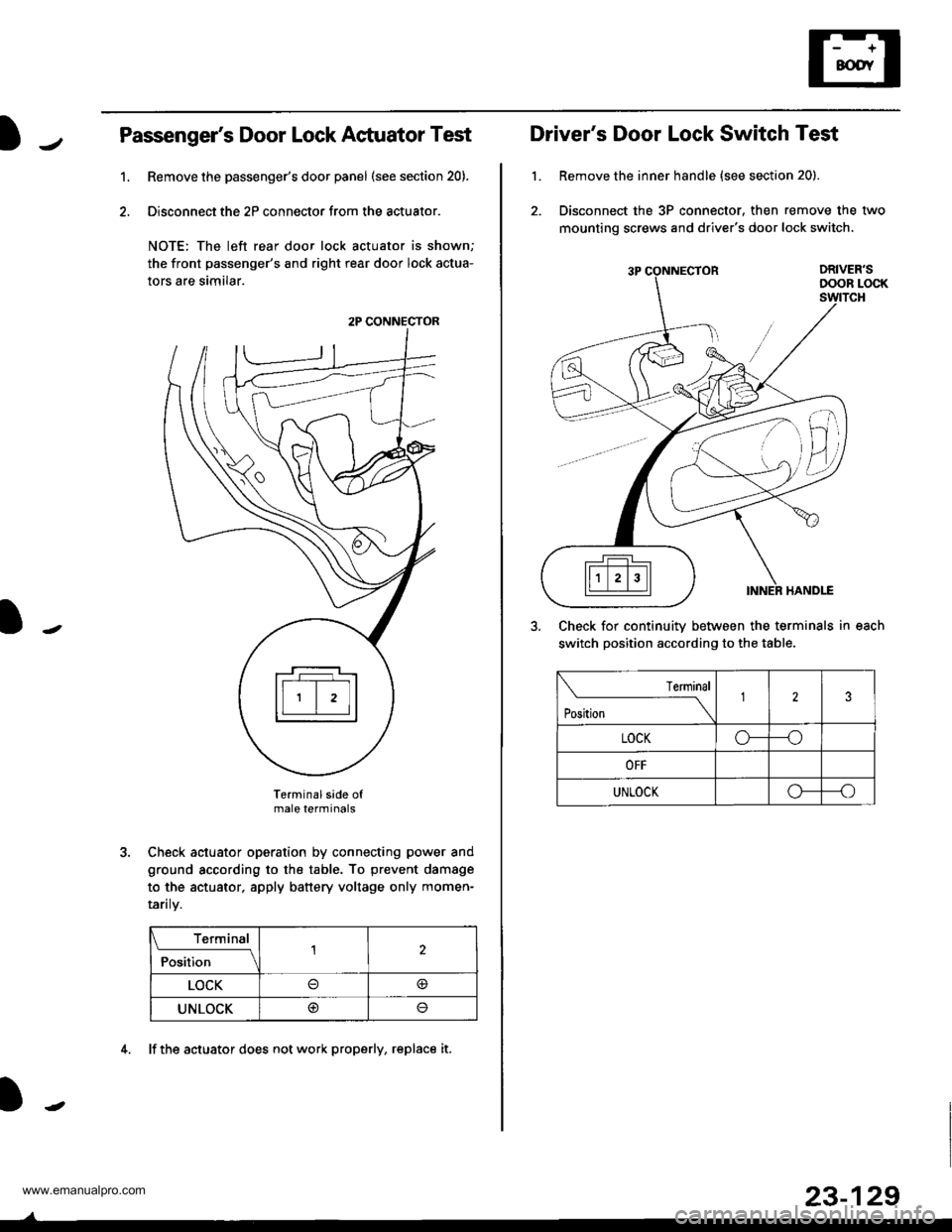
Passenger's Door Lock Actuator Test
Remove the passenger's door panel (see section 20).
Disconnect the 2P connector from the actuator.
NOTE: The left rear door lock actuator is shown;
the front passenger's and right rear door lock actua-
tors are similar.
Terminal side ofmale terminals
Check actuator operation by connecting power and
ground according to the table. To prevent damage
to the actuator, apply battery voltage only momen-
raflry.
Terminal
;;il;--r
,l
LOCK@
UNLOCK@
1.
2P CONNECTOR
4. lf the actuator does not work properly, replace it.
23-129
L
Driver's Door Lock Switch Test
Remove the inner handle {see section 20).
Disconnect the 3P connector. then remove the two
mounting screws and driver's door lock switch.
Check for continuitv between the terminals in each
switch position according to the table.
lermlnal
Position \
123
LOCKo---o
OFF
UNLOCKo--_o
www.emanualpro.com
Page 1295 of 1395
-
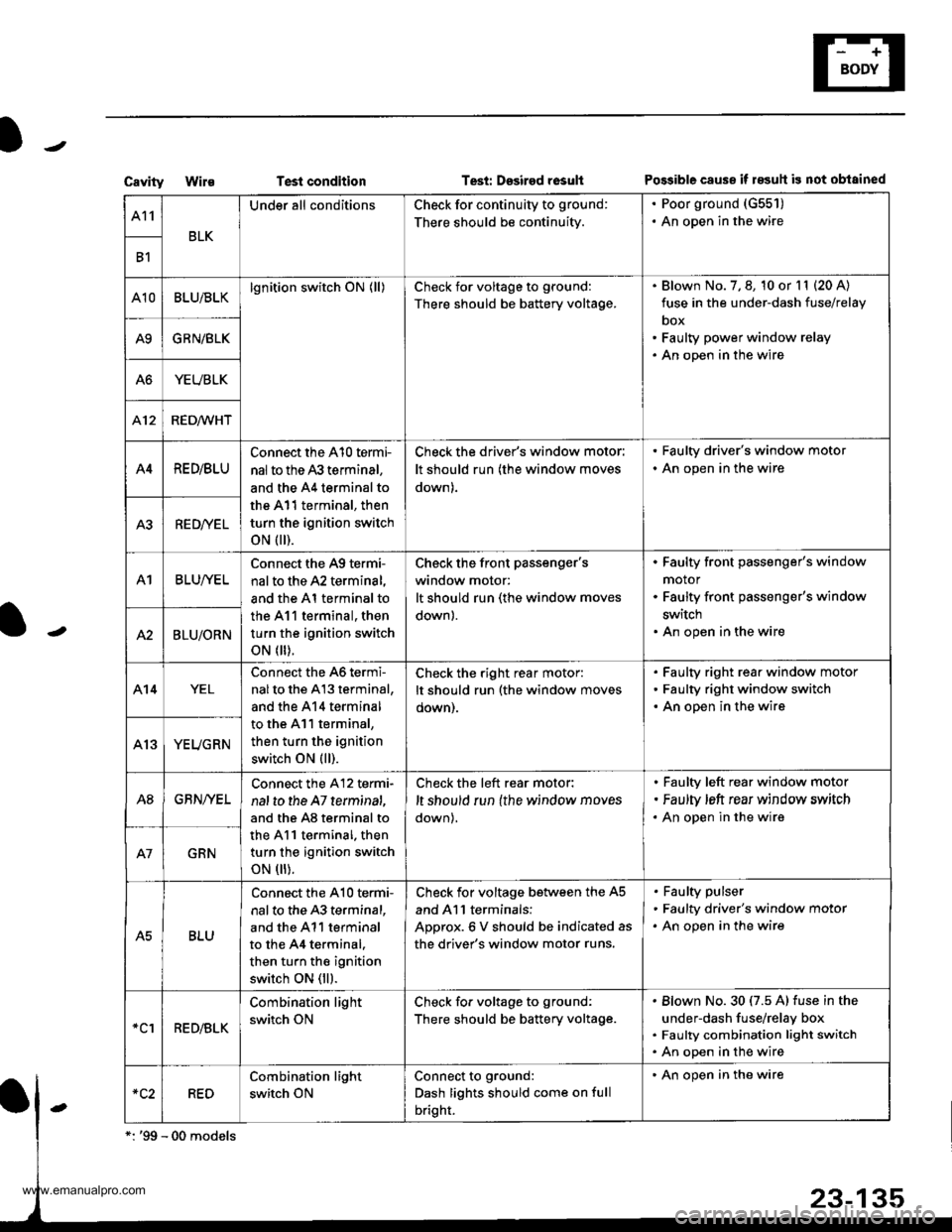
CavityWi1€Test conditionTesi: Dssired rosultPo$ible cause if 183uh is not obtained
A11
BLK
Under all conditionsCheck for continuity to ground:
There should be continuity.
. Poor ground (G551)
. An open in the wire
B1
A10BLU/BLKlgnition switch ON (ll)Check for voltage to ground:
There should be battery voltage.
Blown No. 7, 8, 10 or l1 (20 A)
fuse in the under-dash fuse/relay
box
Faulty power window relay
An open in the wire
A9GRN/BLK
A6YEUBLK
412RED/WHT
A4RE D/BLU
Connect the A10 termi-
nal to the 43 terminal,
and the A4 terminal to
the A11 terminal, then
turn the ignition switch
oN flr).
Check the driver's window motor:
It should run (the window moves
down).
. Faulty driver's window motor
. An open in the wire
A3RED/YEL
A1BLUI/EL
Connect the A9 termi-
nal to the A2 terminal,
and the Al terminal to
the 411 terminal, then
turn the ignition switch
oN flr).
Check the front Passenger'swindow motor:
It should run (the window moves
down).
Faulty front passenger's window
motor
Faulty front passenger's window
switch
An open in the wireA2BLU/ORN
A14YEL
Connect the 46 termi-
nalto the A13 terminal,
and the 414 terminal
to the A11 terminal,
then turn the ignition
switch ON (ll).
Check the right rear motor:
It should run (the window moves
oown).
Faulty right rear window motor
Faulty right window switch
An open in the wire
YEUGRN
A8GBN/YEL
Connect the A12 termi-
nal to the A7 terminat,
and the A8 terminal to
the A11 terminal. then
turn the ignition switch
oN flr).
Check the left rear motor:
,t should run {the window moves
down),
Faulty left rear window motor
Faulty ,eft rear window srrvitch
An open in the wire
GRN
A5BLU
Connect the A10 te.mi-
nal to the 43 terminal,
and the A11 terminal
to the 44 terminal.
then turn the ignition
switch ON (ll).
Check for voltage between the A5
and Al l terminals:
ADorox.6 V should be indicated as
the driver's window motor runs.
Faulty pulser
Faulty driver's window motor
An open in the wire
*clRED/BLK
Combination light
switch ON
Check fo. voltage to ground:
There should be battery voltage.
Blown No.30 (7.5 A) fuse in the
under-dash fuse/relay box
Faulty combination light switch
An open in the wire
RED
Combination light
switch ON
Connect to ground:
Dash lights should come on full
bright.
' An open in the wire
www.emanualpro.com
Page 1323 of 1395
Troubleshooting
Self-diagnostic Procedures
The self-diagnostic function of the SRS system allows it to locate the causes of system problems and to store this informa-
tion in memory, For easier troubleshooting, this data can be retrieved via a data link circuit.
. When you turn the ignition switch ON (ll). the SRS indicator will come on. lf it goes off after six seconds, the system is
normal.
. lf there is 8n abnormality, the system locates and defines the problem. stores this information in memory, and turns
the SRS indicator light on. The data will remain in the memory even when the ignition switch is turned off or if the bat-
terv is disconnected.
. When you connect the SCS service connector to the service check connector (2P), and turn the ignition switch ON (ll),
the SRS indicator light will indicate the diagnostic trouble code (DTC) by the number of blinks.
. After reading and recording the DTC, proceed with the troubleshooting forthis code.
Precsutions
. Use only a digital multimeter to check the system. lf it's not a Honda multimeter. make sure its output is 10 mA (0.01 A)
or less when switched to the smallest value in the ohmmeter range. A tester with a higher output could damage the
airbag circuit or cause accidental airbag deployment and possible injury.
. Whenever the ignition switch isON (ll). or has been turned OFF for less than three minutes, be careful nottobumpthe
SRS unit; the airbags could accidentally deploy and cause damage or injuries.
. Before you remove the SRS main harness, disconnect the airbag and tensioner connectors (see page 24-23).
. Make sure the battery is sufficiently charged (see section 23). lf the battery is dead or low, measuring values won't be
correct.
. Do not touch a tester probe to the terminals in the SRS unit or harness connectors, and do not connect the terminals
with a jumper wire. Use only the backprobe set and the SCS service connector.
For backprobing spring-loaded lock type con nectors, .efet to page 24-22.
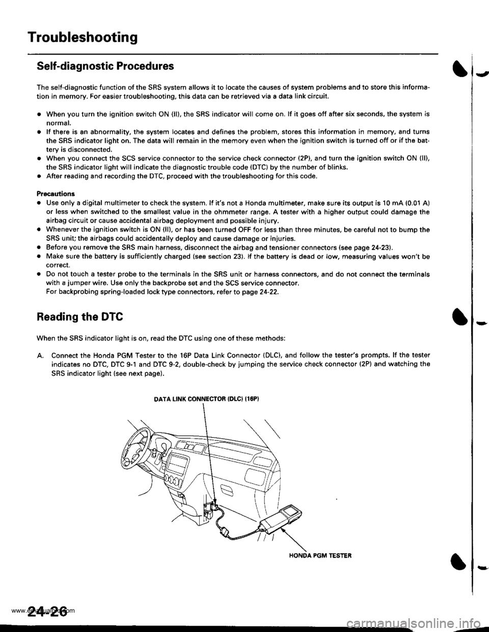
Reading the DTC
When the SRS indicator light is on, read the DTC using one of these methods;
A. Connect the Honda PGM Tester to the 16P Data Link Connector {DLC), and follow the tester's prompts. lf the tester
indicates no DTC, DTC 9-1 and DTC 9-2, double-check by jumping the service check connector (2P) and watching the
SRS indicator light (see next page).
HONDA PGM TESTER
DATA LINK CONNECIOR {DLCI {16P)
24-26
,1
www.emanualpro.com
Page 1348 of 1395
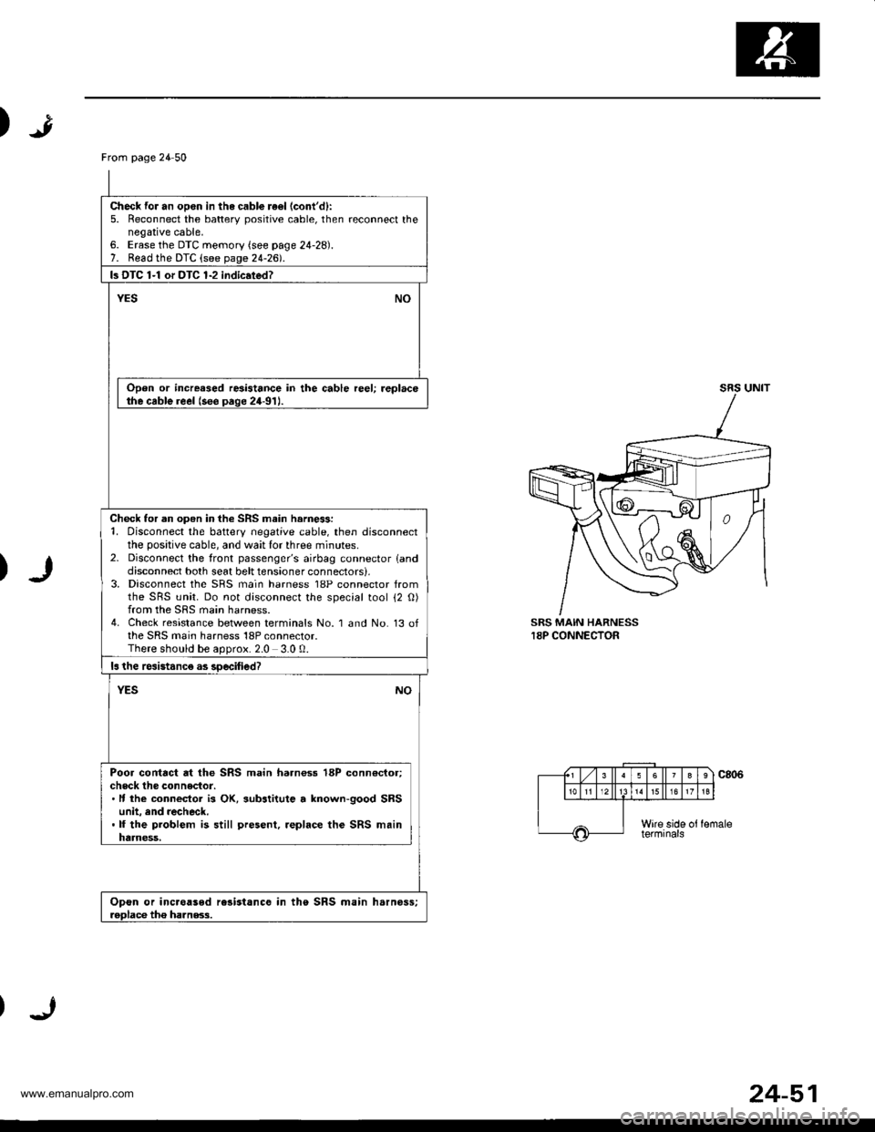
)
)
SRS MAIN HARNESS18P CONNECTOR
From page 24 50
Check for an opon in the cabl€ re€l (cont'd):
5. Reconnect the batterv positive cable, then reconnect thenegative cable,6. Erase the DTC memory (see page 24-28).7. Read the DTC (see page 24-2d.
ls DTC 1-1 or DTC 1-2 indic.ted?
YESNO
Open or increased resistance in the cable reel; replacethe cable reel (see paqe 24-91J.
Check for an open in the SRS main harne$:1. Disconnect the battery negative cable, then disconnectthe positive cable, and wait lor three minutes.2- Disconnect the front passenger's airbag connector landdisconnect both seat belt tensioner connectors),3, Disconnect the SRS main harness 18P connector fromthe SRS unit. Do not disconnect the special tool 12 O)from the SRS main harness.4. Check resistance between terminals No. 1 and No. 13 ofthe SRS main harness 18P connector.There should be aoorox.2.0 3.0 0.
ls the rcsistanc€ as soecified?
NOYES
Poor contact at the SRS main harnoss 18P conn€ctor;check the connector.. It the connecior is OK, substitute a lnown-good SRSunit, and recheck..lf the problem is still present, .eplace the SRS mainharness,
Opon or inc.oased rc3istance in the SRS main harnoss;roDlace tho ha]nss.3.
24-51
www.emanualpro.com
Page 1350 of 1395
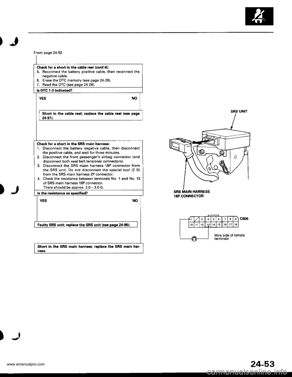
From page 24-52
Chock for a shon in th6 cablo recl {cont'dl:5. Reconnect the battery oositive cable, then reconnect thanegative cable.6. Ersse the DTC memory (see page 24-28).7. Read the DTC (see page 24-26l'.
ls DTC 'l-3 indic{tod?
NOYES
Short in the csble reel; replace tha cabls rcol lsao paga
24-911.
Chock for a short in th€ SRS main ha.nors:1. Disconnect the battery negative cable, th€n disconnectthe Dositive cable, and wait for three minutes.2. Disconn€ct tho lront passengor's airbag connector (and
disconnect both seat belt tensioner connectors).3. Disconnect the SRS main harness 18P connector fromthe SRS {rnit. Do not disconnect the special tool (2 0)from the SRS main harness 2P connector.4. Check the resistance between terminals No. 1 and No. 13of SRS main harness 18P connector.There should be aDorox. 2.0 - 3.0 0.
b th€ rsciitlnce a3 sDecifi6d?
NOYES
Faulty SRS unit; rspl.c. th6 SRS unit l.co p.sc 2a-95,,
Shori in the SRS m.in h.rn.e!; ropbce the SRS main htr-ne33.
SRS UNIT
)SRS MAIN HABNESS18P CONNECTOR
c806
)
(., Lzl 3 ll63
1518
Wire side ottormrnats
24-53
www.emanualpro.com
Page 1364 of 1395
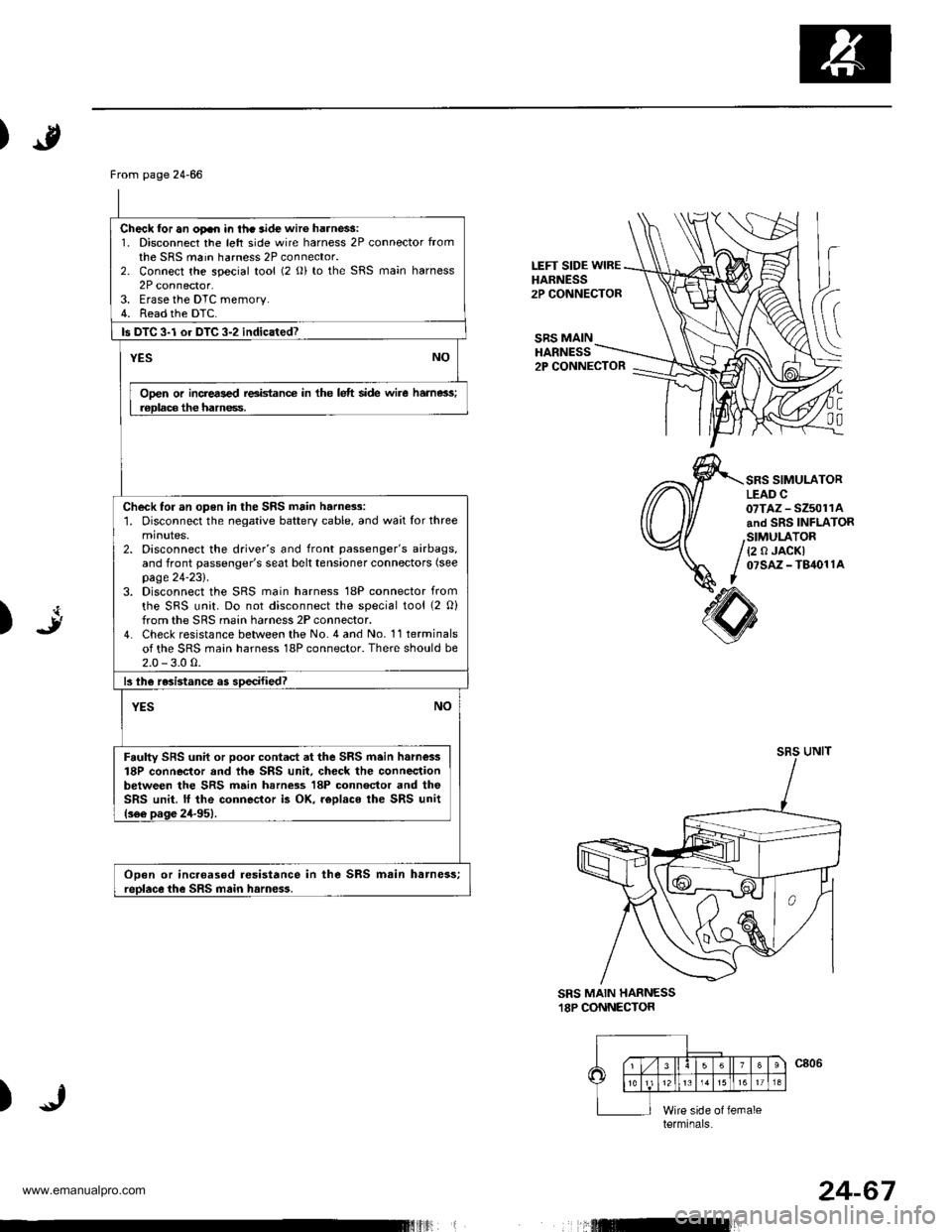
)
LEFT SIDE WIREHARNESS2P CONNECTOR
SRS MAINHARNESS2P CONNECTOR
C
00
SRS SIMULATORLEAD C07TAZ - SZ5011Aand SRS INFLATOR
{2 0 JACKI07sAz - T84011A
art)
sRsUNIT
SRS MAIN HARNESS.I8P CONNECTOR
)
From page 24-66
Check for an oFn in thc aide wir6 harne$:1. Disconnect the left side wire harness 2P connector fromthe SRS main harness 2P connector.2. Connect the special tool (2 o) to the SRS main harness2P connector.3. Erase the DTC memory.4. Read the DTC.
ls DTC 3-l or DTC 3-2 indicated?
YESNO
Ooen or incrers€d reeidance in the lelt side wire hame3s;r€Dlaca the hamess.
Check for an open in the SRS main harness:1. Disconnect the negative battery cable, and wait for threeminutes.2. Disconnect the driver's and front passenger's airbags,and front passenger's seat belt tensioner connectors (see
page 24-231.3. Disconnect the SRS main harness 18P connector from
the SRS unit. Do not disconnect the special tool (2 O)from the SRS main harness 2P connector.4. Check resistance between the No. 4 and No. 11 terminalsof the SRS main harness 18P connector. There should be2.0 - 3.0 0.
13lhe resistance as soecified?
NOYES
Faulty SFS unil or poor contad at the SRS main h.m€ss18P connector and th€ SRS unit. check the connectionbetween the SRS main harn$s 18P connector and theSRS unit. lf the connector i3 OK. r€Dlaco ihe SRS unit(s66 pas6 24-951.
ODen or incaoased resistance in the SRS msin harness;reolace the SRS main harn€ss.
terminals
24-67
www.emanualpro.com
Page 1366 of 1395
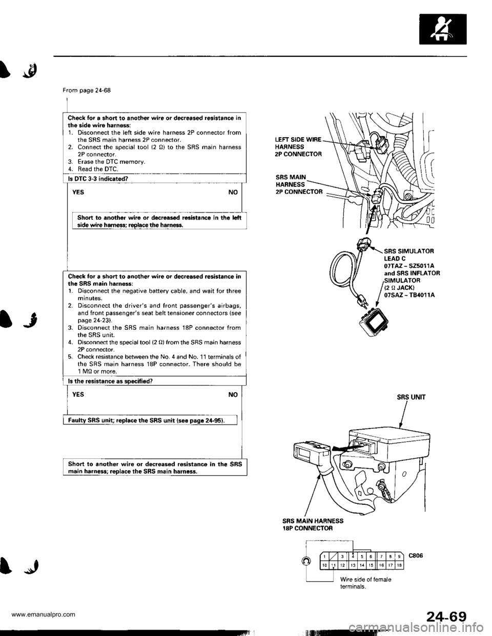
From page 24-68
Check lor a short to another wire or decreased reaistance inthe side wire harnoss:1. Disconnect the left side wire harness 2P connector tromthe SRS main harness 2P connector.2. Connect the special tool (2 0) to the SRS main harness2P connector.3. Erase the DTC memory.4. Read the DTC.
ls OTC 3-3 indicated?
YESNO
Short to another wire or decrcased resbtance in the le-hside wire harness; reglace the harneas.
Check lor a 3hort to another wire or dec.eased resistance inthe SRS main ha.ne$:1. Disconnect the negative battery cable, and wait for threeminutes,2. Disconnect the driver's and front passenger's airbags,and front passenger's seat belt tensioner connectors (seepage 24 23l'.3. Disconnect the SRS main harness 18P connector fromthe SRS unit.4. Disconnect the special tool (2 O) from the SRS main harness2P connector.5. Check resistance between the No. 4 and No. 11 terminals ofthe SRS main harness 18P connector. There should be1 M0 or more.
ls the resistanc€ as soocified?
NOYES
Faulty SRS unit; replace the SRS unit lso€ paqe 24-95).
Short to another wire or decr€asod rosistanco in the SBSmain harness; replace the SRS main harness.
\.p
LEFT SIDE WIREHARNESS2P CONNECTOR
SRS MAINHANNESS
C0a
2P CONNECTOR
SRS SIMULATORLEAD C07TAZ - SZ5011Aand SRS INFLAToRSIMULATOR{2 0 JACK}07sAz - TB4011A
IJ
SRS MAIN HARNESS18P CONNECTOR
SRS UNIT
lerminals.
IJ
t,rutEr-
24-69
www.emanualpro.com