Page 1131 of 1395
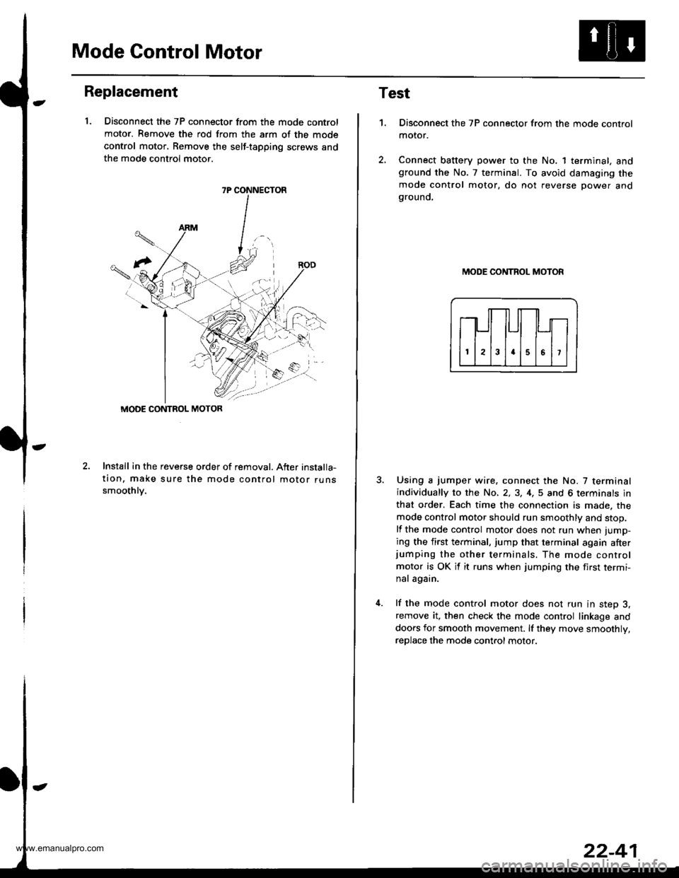
Mode Control Motor
Replacement
1. Disconnect the 7P connector from the mode control
motor. Remove the rod from the arm of the mode
control motor, Remove the self-tapping screws and
the mode control motor.
2.Install in the reveGe order of removal. After installa-
tion, make sure the mode control motor runssmoothlv.
7P CONNECTOR
MODE CONTROL MOTOR
Test
1.Disconnect the 7P connector from the mode control
motor.
Connect battery power to the No. 1 terminal, andground the No. 7 terminal. To avoid damaging the
mode control motor, do not reverse power andgrouno.
MODE CONTROL MOTOR
Using a jumper wire. connect the No. 7 terminalindividually to the No, 2,3, 4,5 and 6 terminals in
that order. Each time the connection is made. the
mode control motor should run smoothly and stop.
lf the mode control motor does not run when jump-
ing the first terminal, jump that terminal again afterjumping the other terminals. The mode control
motor is OK it it runs when jumping the first termi-
nal again.
lf the mode control motor does not run in step 3,remove it, then check the mode control linkage and
doors for smooth movement. lf they move smoothly,
reDlace the mode control motor.
www.emanualpro.com
Page 1225 of 1395
< - ELK/WHT
S'TARTEBCUTRELAY
A,/rGEARPOSrr 0N SWTTCH(CLOSED :ln postion Eor N)
COMBINATONLIGHT SWITCH
\-/
IRED/GRN
I
.l-
NTEGRATED CONTROL UNIT
POWERDOOR LOCKCONTROL UNIT
I B1o PowERBLU/RED DOOR LOCK
I CONTFOL UN T
IY
F r,r'tro J
BLUi RED
"l\
u/
llon. no*
155,1'*IaCLOSED Keylnseded
| \oPEN Key rcmoved
8LK
4
G40r
LTGRN/RED LTGRN/RED LTtl
/rh d[)v !s-l
I FFONT I LEFTI PASSENGEBS I REABI DOOR | 00ORoDen ) lSwlTcH I SWITCHdosedJ J f C-OSED : ooot ooer ) | f CLOSED : Door opel
| ( ooE Doot dosed,r | \oPEN Doo' closed
tl_L -._:-
1,,,,,"
Yilei'rGRN/RED
. BNAKE FLUIOLEVEL SWITCH.PARKING ERAKEswrTcH (usA)
A8
BRAKE BULBCHECKCIFCUTKEY.IN]SEAT BELT and LIGHTS'ONREMINDER C RCU T
23-65
www.emanualpro.com
Page 1228 of 1395
Integrated Gontrol Unit
Input Test -'97 Model
SRS components are located in this area. Review the SRS component locations, precautions, and procedures in the SRS
section {24) before performing repairs or service.
'1. Remove the driver's dashboard lower cover and the knee bolster (see section 20).
2. Disconnect the 'l0P connector from the inteorated control unit.
3. Remove the integrated control unit from the under-dash fuse/relay box.
4. Inspect the connector and socket terminals to be sure they are all making good contact.
. lf the terminals are bent, loose or corroded, repair them as necessary, and recheck the system.
.lftheterminalslookOK,makethefollowinginputtestsattheconnectorandthefuse\
/relayboxsocket.- lf any test indicates a problem, find and correct the cause, then recheck the system.- lf all the input tests prove OK, the control unit must be faulty; replace it.
INTEGRATEO CONTROL UNIT
rOP CONNECTOR
female terminals
23-68
www.emanualpro.com
Page 1231 of 1395
Input Test -'98 - 00 Models
SRS components are located in this area. Review the SRS component locations, precautions, and procedures in the SRS
section (24) before performing repairs or service.
L Remove the driver's dashboard lower cover and the knee bolster (see section 20).
2. Disconnect the 'l5P connector from the inteqrated control unit.
3. Remove the integrated control unit from the under-dash fuse/relay box.
4. Inspect the connector and socket terminals to be sure they are all making good contact.
. lf the terminals are bent, loose or corroded. repair them as necessary, and recheck the system.
.lftheterminalslookOK,makethefollowinginputtestsattheconnectorandthefuse\
/relayboxsocket.
lf any test indicates a problem, find and correct the cause, then recheck the system.- lf all the input tests prove OK, the control unit must be faulty; replace it.
UNDER-DASHFUSE/RELAY BOX
INTEGRATED CONTROL UNIT
15P CONNECTOR
A8<------A14
YEL/BLU LT GRN WHT/BLK
www.emanualpro.com
Page 1239 of 1395
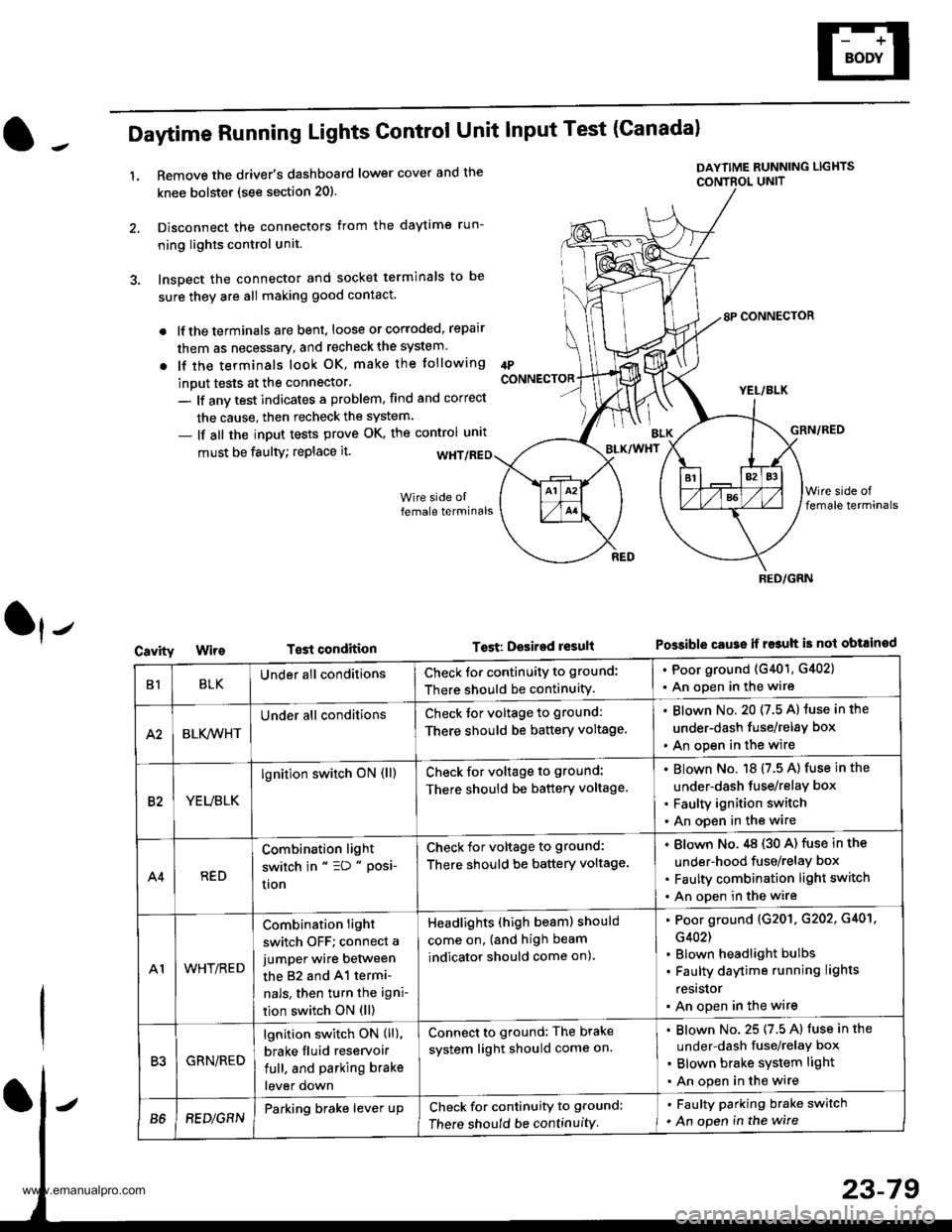
Daytime Running Lights Control Unit Input Test (Canadal
1.Remove the driver's dashboard lower cover and the
knee bolstet (see section 20).
Disconnect the connectors from the daytime run-
ning lights control unit.
Inspect the connector and socket terminals to be
sure they are all making good contact.
lf the terminals are bent, loose or corroded, repair
them as necessary, and recheck the system.
lf the terminals look OK, make the tollowing
inout tests at the connector'
- lf anv test indicates a problem, find and correct
the cause, then recheck the system.
- lf all the input tests prove OK, the control unrt
IPCONNECTOR
must be faulty; replace it.
T€st condition
DAYTIME RUNNING LIGHTS
CONTBOL UNIT
Tost: Desired result
8P CONNECTOR
YEL/BLK
GRN/RED
Possible cause ii r$uh is not obtained
BLK/WHT
Cavity
RED/GRN
B1BLKUnder all conditionsCheck for continuity to ground:
There should be continuity.
. Poor ground (G401, G402)
. An open in the wire
A2BLK,4iVHT
Under all conditionsCheck tor voltage to ground:
There should be battery voltage.
Blown No. 20 (7.5 A) luse in the
under-dash fuse/relay box
An open in the wire
82YEUBLK
lgnition switch oN (ll)Check for voltage to ground:
There should be battery voltage.
Blown No. 18 (7.5 A) fuse in the
under-dash tuse/relay box
Faulty ignition switch
An open in the wire
A4RED
Combination light
switch in " =D " Posi-
uon
Check for voltage to ground:
There should be battery voltage.
Blown No.,tg (30 A) fuse in the
under-hood fuse/relay box
Faulty combination light switch
An open in the wire
A1WHT/RED
Combination light
switch OFF; connect a
jumper wire between
the 82 and 41 termi-
nals, then turn the igni-
tion switch ON (ll)
Headlights (high beam) should
come on, (and high beam
indicator should come on).
Poor ground (G201. G202, G401,
G402)
Blown headlight bulbs
Faulty daytime running lights
resrslor
An open in the wire
R'IGRN/RED
lgnition switch ON (ll),
brake fluid reservoir
full. and parking brake
lever down
Connect to ground: The brake
system light should come on.
Blown No. 25 (7.5 A) fuse in the
under-dash fuse/relaY box
Blown brake system light
An open in the wire
B68EDlGRNParking brake lever upCheck for continuity to ground:
There should be continuity
. Faulty parking brake switch
. An open in the wire
www.emanualpro.com
Page 1246 of 1395
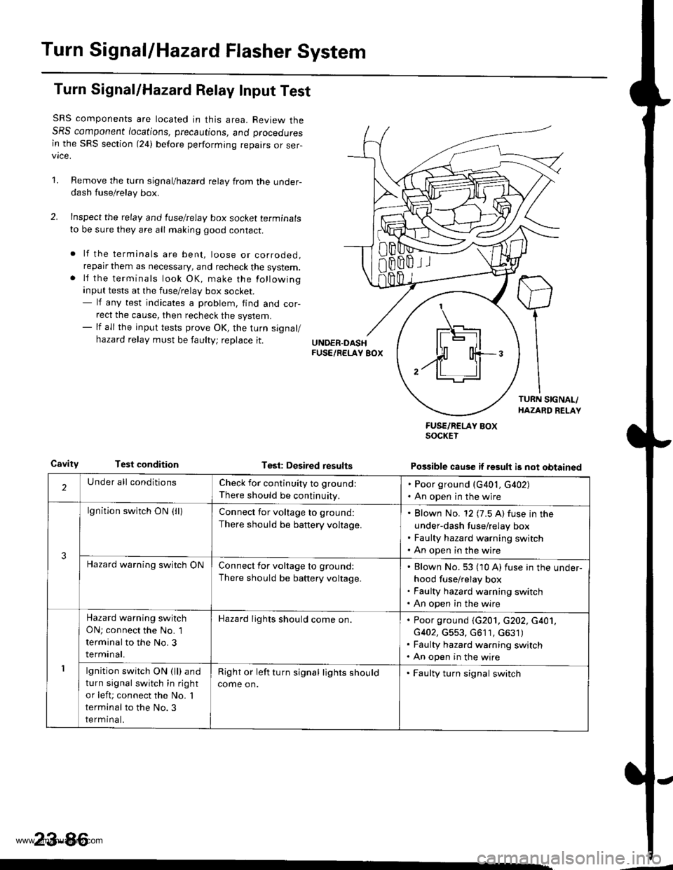
Turn SignallHazard Flasher System
Turn Signal/Hazard Relay Input Test
SRS components are located in this area. Review theSRS component /ocations, precautions, ano proceoures
in the SRS section (24) before performing repairs or ser-vice.
1.Remove the turn signal/hazard relay from the under-dash fuse/relay box.
Inspect the relay and luselrelay box socket terminals
to be sure they are all making good contact.
lf the terminals are bent, loose or corroded,reparr them as necessary, and recheck the system.lf the terminals look OK, make the following
input tests at the fuse/relay box socket.- lf any test indicates a problem, find and cor-
rect the cause, then recheck the system.- lf all the input tests prove OK, the turn signal/
hazard relay must be faulty; replace it.
CavityTest conditionTesl: Desired results
FUSE/RCLAY BOXSOCKET
Possible cause if result is not obtained
'1
IF\_-'l -]l
$ o{+-/ll ll
2Under all conditionsCheck for continuity to ground:
There should be continuity.
. Poor ground (G401, G402). An open in the wjre
3
lgnition switch ON (lllConnect for voltage to ground:
There should be battery voltage.
Blown No. 12 (7.5 A) fuse in the
under-dash fuse/relay box
Faulty hazard warning switch
An open in the wire
Hazard warning switch ONConnect for voltage to ground:
There should be battery voltage.
Blown No. 53 (10 A) fuse in the under-
hood fuse/relay box
Faulty hazard warning switch
An open in the wire
1
Hazard warning switch
ON; connect the No. 1
terminal to the No. 3
terminal.
Hazard lights should come on.Poor ground (G201. c202, c401,
G402, G553, G611, c631)
Faulty hazard warning switch
An open in the wire
lgnition switch ON (ll) and
turn signal switch in right
or left; connect the No. 'l
terminal to the No.3
terminal.
Right or left turn signal lights should
come on.
. Faulty turn signal switch
23-86
www.emanualpro.com
Page 1249 of 1395
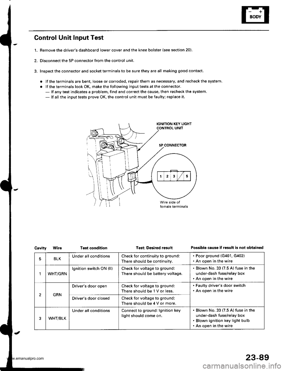
Control Unit Input Test
l. Bemove the driver's dashboard lower cover and the knee bolster (see section 20).
2, Disconnect the 5P connector from the control unit.
3. Inspect the connector and socket terminals to be sure they are all making good contact.
. lf the terminals are bent, loose orcorroded, repairthem as necessary, and recheck the system.
. lf the terminals look OK, make the following input tests at the connector.- lf any test indicates a problem, find and correct the cause. then recheck the system.
- lf all the input tests prove OK, the control unit must be faulty; replace it.
IGNITION KEY LIGHTCONTROL UNIT
5P CONNECTOR
\
))
Test conditionCavityWireTest: Desired resultPossible cause if r€sult is not obtained
BLKUnder all conditionsCheck for continuity to ground:
There should be continuity.
. Poor ground {G401, G402}. An open in the wire
'IWHT/GRN
lgnition switch ON (ll)Check for voltage to ground:
There should be battery voltage.
. Blown No. 33 (7.5 A) fuse in the
under-dash fuse/relay box. An open in the wire
GRN
Driver's door openCheck for voltage to ground:
There should be 1 V or less.
. Faulty driver's door switch. An open in the wire
Driver's door closedCheck for voltage to ground:
There should be 4 V or more.
WHT/BLK
Under all conditionsConnect to ground: lgnition key
light should come on.
Blown No. 33 (7.5 A) fuse in the
under-dash fuse/relay box
Blown ignition key light bulb
An open in the wire
23-89
www.emanualpro.com
Page 1251 of 1395
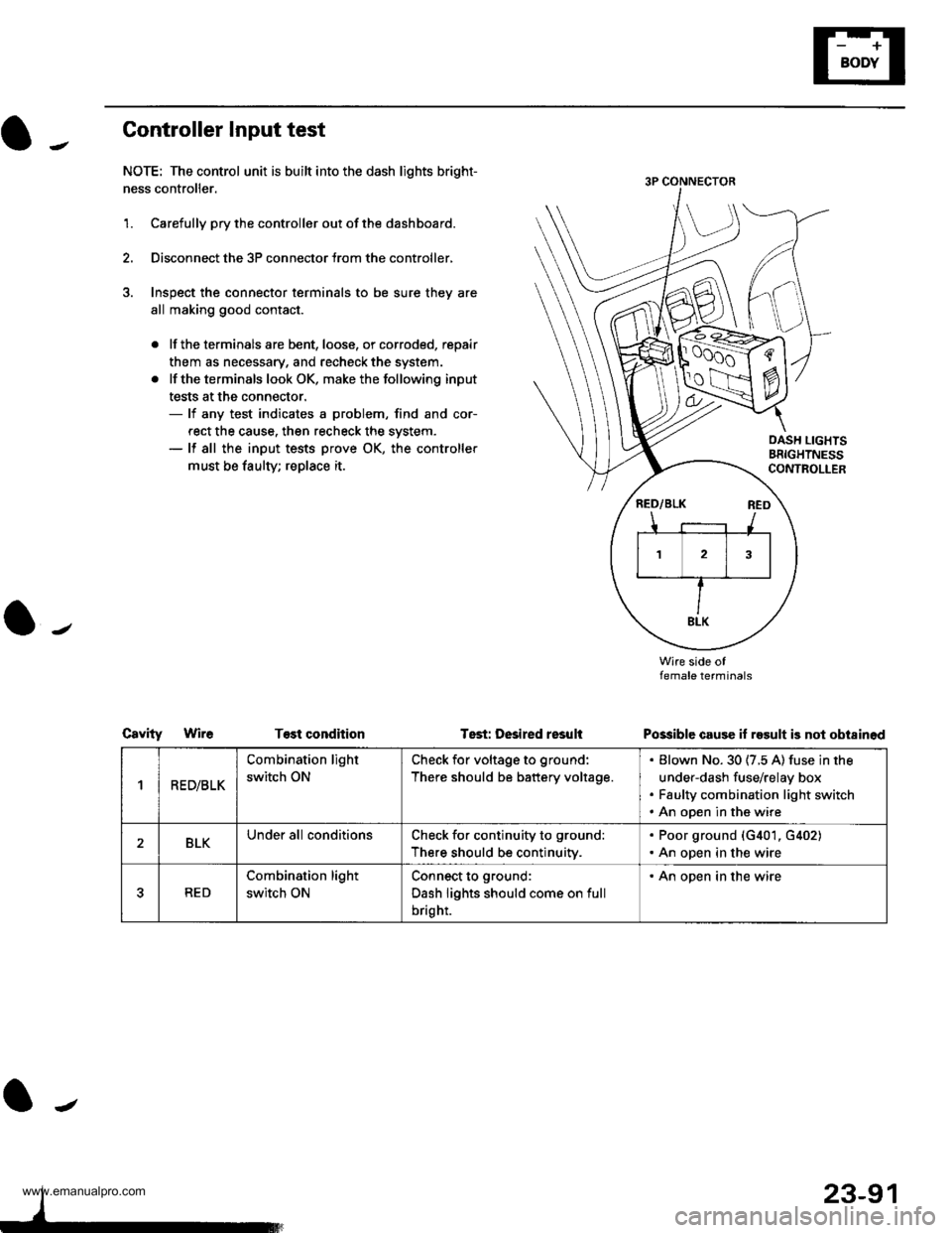
Controller Input test
NOTE: The control unit is built into the dash lights bright-
ness controller.
1.Carefully pry the controller out of the dashboard.
Disconnect the 3P connector trom the controller,
Inspect the connector terminals to be sure they are
all making good contact.
. lf the terminals are bent, loose, or corroded, repair
them as necessary, and recheck the system.
. lf the terminals look OK, make the following input
tests at the connector.- lf any test indicates a problem, find and cor-
rect the cause. then recheck the system.- lf all the input tests prove OK, the controller
must be taulty; replace it.
CsvityWireT€st condhion
Wire side oflemale terminals
Possible cause if result is not obi8inod
OASH LIGHTSBRIGHTNESSCONTROLLER
Tsst: Desired resuli
1R ED/BLK
Combination light
switch ON
Check for voltage to ground:
There should be battery voltage.
Blown No. 30 (7.5 A) fuse in the
under-dash fuse/relay box
Faulty combination light switch
An open in the wire
2BLKUnder all conditionsCheck for continuity to ground:
There should be continuitv.
. Poor ground (G401, G402). An open in the wire
5RED
Combination light
switch ON
Connect to ground:
Dash lights should come on full
bright.
. An open in the wire
23-91
www.emanualpro.com