Page 536 of 2189

1\
Evaporative Emission (EVAPI Controls
Description
The evaporative emission controls are designed to minimize the amount of fuel vapor escaping to the atmosphere. The
system consists of the foliowing components:
A. Evaporative Emission (EVAP) Control Canisto]
An EVAP control canister is used for the temporary storage of fuel vapor until the fuel vapor can be purged from the
EVAP control canister into the engine and burned.
B. Vapor Purge Control System
EVAP control canister purging is accomplished by drawing fresh air through the EVAP control canister and into a port
on the intake manifold. The purging vacuum is controlled by the EVAP purge control solenoid valve.
I'96 D16Y5 engine,'96 Dl6Y7 engine,'96 D16Y8
engine (sedan),'97 D16Y5 engine,'97 D16Y7
engine (couper KA, KC models, sedan: KA, Kc'
KL iDX) models, hatchback: all models), '97
D 16Y8 engine (sedan: KA, KC models)l
I'96 D16Y8 engine (coupe),'97 D16Y7 engine
(coupe: KL model, sedan: KL (LX) model)"97
D16Y8 engine (coupe: all models, sedan: KL model)'98-all models,'99-all models,'00-all modelsl
I
c.
D.
or
l'lc COMPRESSOR CLUTCH ON
and
INTAKE AIR TEMPERATURE ABOVE 160"F (41'C)
Fuel Tank Vapor Control System
When fuel vapor pressure in the fuel tank is higher than the set value of the EVAP two way valve, the valve opens and
regulates the flow of fuel vapor to the EVAP control canister.
Onboard Refueling Vapor Recovery (ORVRI System {'99 - 00 models}
During refueling. the oRVR {onboard Refueling Vapor Recovery) vent shut valve opens with the pressure in the fuel
tank. and feeds the fuel vapor to the EVAP control canister.
t(cont'd)
11-267
EVAP PURGE CONTROL SOLENOID VALVE DUTY CON-
TROLLED AFTER STARTING ENGINE
ENGINE COOLANT TEMPERATURE ABOVE 154'F {68"C)
INTAKE AIR TEMPERATURE ABOVE 32'F (O'C)
and
VEHICLE SPEED ABOVE O MILE (O KM/h}
ENGINE COOLANT TEMPERATURE ABOVE 154'F (68'C)
Page 585 of 2189

Transmission Assembly
I
Removal
@. Make sure iacks and safety stands are placed prop€dy,
and hoist brackets are atlach€d to correct position on
the enginc.
. Apply parking brake and block rear whosls so car will
nol roll olf stands and lall on you while working under
it.
CAUTION: Use fender covers to svoid damaging painted
surfaces.
1. Disconnect the negative {-) cable first, then the pos-
itive (+) cable from the battery'
Drain transmission oil {see page 13-3).
Remove the intake air tube. intake air duct and air
cleaner housing assembly (see section 5).
Disconnect the starter motor cables, transmission
ground wire and back-up light switch connector.
6x1.0 mm BACK-UP LIGHT
9.8 N.m (1.0 ksf.m, 7.2 lbI.ft) swlTcH CoNNECTOR
8x 1 .25 mm8.8 N.m {0.9 kgt.m,6.5 lbf.ftl
\
ARTER
5. Remove the wire harness clamps.
vssCONNECTOR
6. Disconnect the vehicle speed sensor (VSS) connec-
ror.
Remove the clutch line bracket, clutch line clamp,
and slave cvlinder.
CAUTION:
. Do not opsr.te tho clutdh pedal once the 3lavc
cylindor has b6on romoved.
. Tske care not to bend tha clutch lin6.
7.
(cont'd)
13-5
Page 628 of 2189

Transmission Assembly
l
,
{
Removal
@Make sure iacks and safoty stands are placad plop-
erly (3ee section l).
Apply parking braks and block rear wheels so car
will not roll off stands and fall on you while working
under il.
CAUTION: Us6 fonder cove6 to avoid damaging painted
sudaces.
Disconnect the negative (-) cable from the battery,
then the positive (+l cable.
Drain the transmission oil. then reinstall the drain
plug with a new washer (see page 13-47).
Remove the intake air duct and the air cleaner hous-
ing assembly (see s€ction 5).
Disconnect the back-up light switch connector and
the transmission ground wire.
Remove the lower radiator hose clamp from the
transmission hanger B.
L
8 x 1 .25 mm22Nm12.2kgl'm�,
LOWER RADIATORHOSE CLAMP
16 rbtft)
13-48
7.
Bemove the wire harness clamps.
Disconnect the starter motor cables and the vehicle
speed sensor (VSS) connector.
8 x 1.25 mm8.8 N.m (0.9 kgf.m,6.5 tbtftl
STARTERMOTORCABLES
8. Remove the clutch line bracket and the slav6 cylin-
oer.
NOTE: Do not operate the clutch pedal once the
slave cylinder has been removed.
\J
Page 800 of 2189
Transmission
Removal
@Maks sure lifts, iacks and safety stands are placedproperly, and hoist bracket ate aftached to the cor_rec{ position on the engine lsee section 1).Apply parking brake and block rear whoels so vehiclewill not roll off stands and fall on you while workingunder it.
CAUTION: Use tender covers to avoid damaging paint-ed surfaces.
1, Disconnect the battery negative (_) terminal fromthe battery, then remove the positive (+) terminal.
2. Remove the intake air duct.
D16Y7 engins:
Remove the intake air duct and resonator.
D16Y8 engine:
Remove the intake air duct and the air cleaner hous-ing assembly,
3. Remove the starter cables and cable holder fromthe starter motor.
MOTOR CABLE
MOTOR CABLE
14-122
4. Remove the transmission ground cable, and discon_nect the lock-up control solenoid connector.
LOCK.UP CONTROLSOLENOID CONNECTOR
5, Disconnect the vehicle speed sensor (VSS) connec_tor and the countershaft speed sensor connector.
VEHICLE SPEED
Page 864 of 2189

Transmission
Installation {cont'd)
Connect the lock-up control solenoid connector. andinstall the transmission ground cable.
6 x '1.0 mm12 N.m {1.2 kgf.m, 8.7 lbl.ft}
LOCK.UP CONTROLSOLENOID CONNECTOR
Connect the staner cables on the staner motor. andinstall the cable holder.
NOTE; When installing the starter cable terminal.make sure that the crimped side of the ring terminalis facing out (see section 23).
6x1.0mm12 N.m 11.2 kg{.m.8.7 tbtftl
{0.9 kg'f.m, 7 lbf.ftl
TRANSMISSIONGROUND CABLE
b
14-186
STARTER CAELE
24. Installthe intake air duct.
D16Y7 engine:
Install the intake air duct and the resonaror.
D16Y8 engine:
lnstall the intake air duct and the air cleaner hous_ang assembly.
25. Refill the transmission with ATF (see page 14_1.18).
26. Connect the positive (+) cable first. then the nega-tive (-) cable to the battery.
27. Check the ignition timing (see section 23).
28. Start the engine. Set the parking brake, and shift thetransmission through all gears. three times. Checkthe shift cable adjustment (see page 14_190).
29, Check the front wheel alignment (see section 1g).
30. Let the engine reach operating temperature (thecooling fan comes on) with the transmission in Nor @ position, then turn it off and check the fluidlevel (see page 14- 7).
31. Road test as described on pages 14-113 thru ,14_116.
Page 981 of 2189

Transmission
Removal
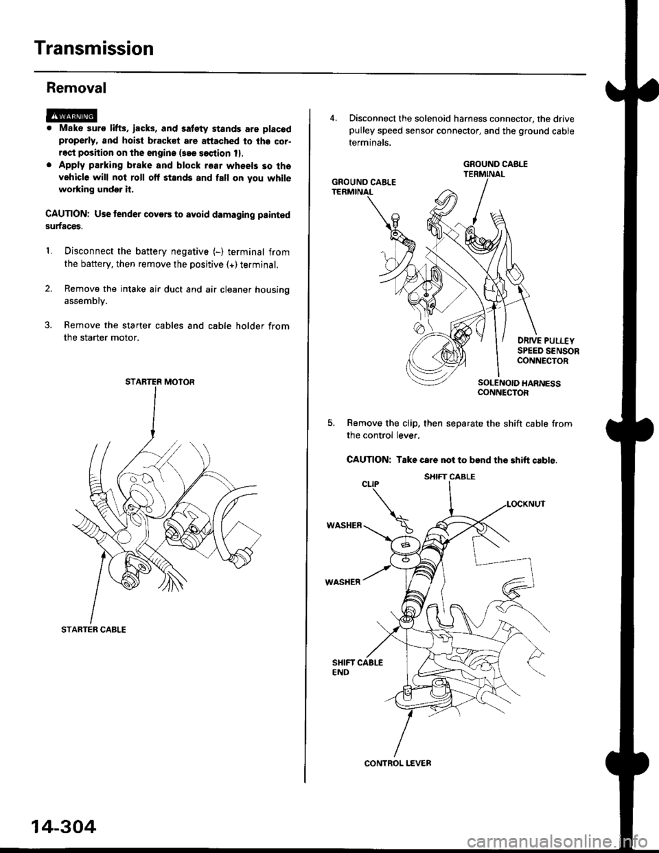
@. Mako suro lifts. iacks, and satety stands are placod
properly, and hoi3t bracket are attached to lhe cor-
rect position on the engine {see soction 1}.
. Apply parking brake and block r€ar wheels so tha
vehicle will not roll off stands and fall on you while
working undor it.
CAUTION: Use tender covers to avoid damaging painted
surfaces.
Disconnect the battery negative (-) terminal from
the battery, then remove the positive (+)terminal.
Remove the intake air duct and air cleaner housing
1.
assembly.
3. Remove the starter cables and cable holder from
the starter motor.
STARTER CABLE
STARTER MOTOR
14-304
4, Disconnect the solenoid harness connector, the drivepulley speed sensor connector, and the ground cable
terminals.
DRIVE PULI.-EYSPEED SENSORCONNECTOR
SOLENOIO HARNESSCONNECTOR
Remove the clip, then separate the shift cable from
the control lever,
CAUTION: Take care not to bend the shift cable.
WASHER
WASHER
GROUND CABLE
GROUND CAELE
CONTROL LEVER
S}IIFT CABLE
Page 1027 of 2189

22. Install the shift cable end on the control lever, and
install the shift cable on the shift cable bracket'
CAUTION: Take care not to bend the shift cable'
23. lnstall the clip in the direction shown.
LOCKNUT
SHIFI CABLE 29 N m {3.0 kg{ m, 22lblftl
SHIFT CABLEERACKET
WASHERIPLASTIC)
CONTROL LEVER
24, Connect the solenoid harness connector. the drive
pulley speed sensor connector. and the ground
cable terminals.
6x1.0mm12 N.m {1.2 kgf.m.8,7 rbtft)
GROUND CABLETERMINAL 6x1.0mm
GROUNDTERMINAL
12 N.m {1.2 kgf'm,8.7lbtfrl
DRIVE PULLEYSPEED SENSORCONNECTOR
SOLENOID HARNESS
CONNECTOR
25. Connect the starter motor cable on the starter motor.
and install the cable holder.
NOTE: When installing the staner motor cable. make
sure that the crimped side of the ring terminal is
facing out (see section 23).
STARTEB
BMOUNTING NUT
9 N.m (0.9 kgf m,7 lbf ft)
26. Install all removed connectors and clamps'
27. Install the distributor.
28. Install the intake air duct and air cleaner housing
29.
assemDly.
Refill the transmission with the recommended
Genuine Honda CVT Fluid (see page 14-2991
CAUTION: While filling the CvT Fluid, bs surs not io
allow dust and other fotoign particles to entor into
the transmission.
Connect the battery positive (+) terminal first, then
the negative (-l terminal to the battery'
Check the ignition timing (see section 23).
Start the engine. Set the parking brake, and shift the
transmission through all gears three times Check
shift cable adjustment (see page 14-355).
Check the front wheel alignment (see section 18)
Let the engine reach operating temperature (the
radiator fan comes on) with the transmission in lXl
or E position, then turn it off and check fluid level'
Perform the start clutch calibration procedure on
page 14-293.
Road test as described on pages 14-296 and 14-297
30.
31.
34.
36.
STARTER MOTOR
14-351
Page 1449 of 2189

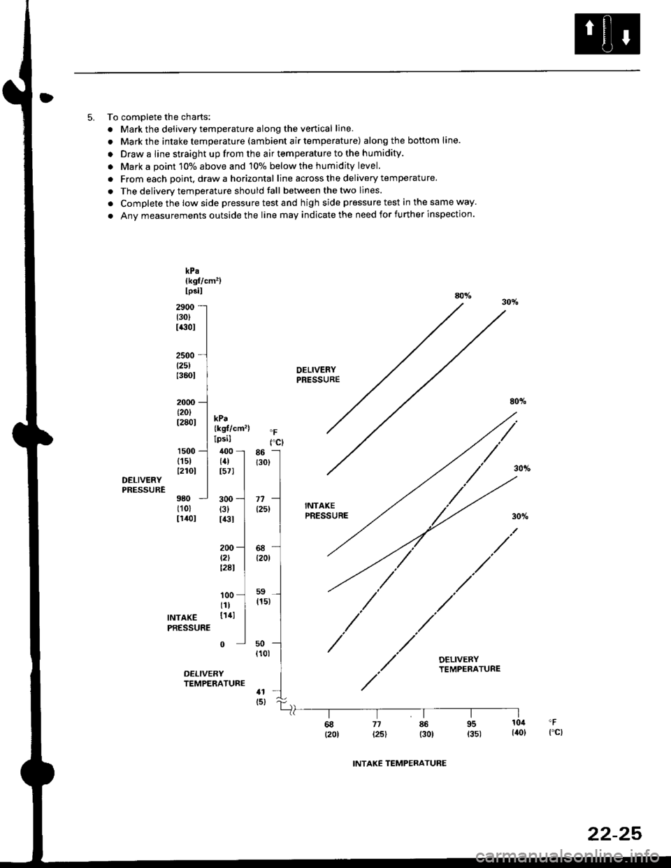
5. To complete the charts:
. Mark the delivery temperature along the venical line.
. Mark the intake temperatu re (am bient a ir temperatu re) alongthe bottom line.
. Draw a line straight up from the air temperature to the humidity.
. Mark a point 10% above and 10% below the humidity level.
. From each point. draw a horizontal line across the delivery temperature.
. The deliverv temperature should fall between the two lines.
. Complete the low side pressure test and high side pressure test in the same way.
. Any measurements outside the line may indicate the need for further inspection.
rct86 -l
r3ol
I
A,-]
I68-{20r I
,r-]"'l
uo --]
''o'
I
nt
300{3}I€I
200l2lt28l
kPalkgf/cm'�llpsilaoy.30io2900 -
(30)
I€OI
2500 -
(25)
13601
2000 -
t20lt280t
1500 -
{15112101DELIVERYPRESSURE980 -
(101
lr40l
DELIVERYPRESSURE
80%
kPa{kgf/cm'�)lpsil
400 -
{4)t571
INTAXEPRESSURE
100tll
INTAKE 1141
PRESSURE
0
DELIVERYTEMPERATURE
68 77 86 95 10il 'F
(2ot t2sl t3o) 135) l4ol {"c)
INTAKE TEMPERATURE
22-25