Page 862 of 2189

Transmission
Installation (cont'dl
9. Attach the torque converter to the drive plate witheight drive plate bolts and torque as follows:Rotate the crankshaft pulley as necessary to tightenthe bolts to 1/2 of the specified torque. then to thefinal torque, in a crisscross pattern.
After tightening the last bolt, check that the crank-shaft rotates freely.
TOROUE: 12 N.m {1.2 kgl.m, 8.7 tbt{r}
10 x 1.25 mm
6x1.0mm12 N.m (1.2 kgt m,8.7 rbt ft)
I 1.25 mm2/t N.m {2.4 kg{.m,17 tbt ftlCONVERTEB
10. Install the torque convener cover and the €nginestiffener.'11. Tighten the crsnkshaft pull€y bolt, if necessary (see
section 61.
12. Connect the ATF cooler hoses to the ATF cooler lines(see page 1,t192).
ATF COOIIRUNE
10 x 1.25 mma,l N.m {4.5 kgl.m,33 rbt.fttRIGHT FRONT 12 x 1.25 mmMOUNT/BRACKET 6.t N.m (6.5 kg{.m,47 tbt ftl
13. Install the right front mounvbracket.
4,r N.m 14.5 kgf.m,33 lbtft)
COVER
L,
14-1A4
SHIFT CABLE
SHIFT CAAE COVER
14. Install the control lever with a new lock washer tothe control shaft, then install the shift cable cover.
CAUION: Taks care not to bend the shift cable.
L(rcK WASHERReplace.
8 x 1,25 r'|m22N-m12.2 tgt m. 16lbnftl
x 1.0 mmtit N.m 11.4 kgt m,10 tbr,ft,
15. lnstall the exhaust pipe A.
NOTE: D16Y8 engine is shown; D16y/ engine is sim_ilar.
Replace.
GASKETReplace.
SELF.LOCKING NUTReplace.10 x 1.25 mm54 N.m (5.5 lgf.m,40 tbt ftl
NUTSELF.LOCKING NUTReplace.8 x 1.25 mm22 N.m {2.2 kgl.m, 16lbtfrl
Replace.8 x 1.25 mm16 N.m {1.6 kgI.m,12 tbf.ft)
Page 986 of 2189
O ATF DIPSTICK
O o-RING Replace.
.' SOLENOID HARNESS CONNECTOR
@ LOWER VALVE BODY ASSEMBLY
O DOWEL PIN
O LINE BOLT
.i ATTf COOUR IruIET LINE B8ACKET BOLT
€] lrr cooua truler LINE ASSEMBLY
O SEALING WASHER RePIACE'
G, ATF COOLER OUTLET PIPE
6) o-RING Replace.
@ ATF FILTER
fO o-RING Replace.
@ ATF PAN(3 DOWEL PIN(D O-RING Replace.
E) ATF STRAINER
@ ATF MAGNET(9 ATF PAN GASKET RePIACE'
O ATF MAGNET
€t oRAIN PLUG
@ SEALING wAStlER Replace.
TOROUE SPECIFICATIONS
Bolt/Nut No.Torque ValueSizeRemarks
8F
12J
18D
12 N.m {1.2 kgf m, 8.7 lbf'ft}
26 N.m (2.7 kgim,20 lbf'ft)
28 N.m (2.9 kgf'm,21 lbf'ft)
49 N.m (5.0 kgf'm, 36 lbf'ft)
6x1.0mm
8 x 1.25 mm
12 x 1.25 mm
18 x 1.5 mm
Line bolt
Drain plug
14-309
Page 1007 of 2189
Differential
Bearing Replacement
NOTE: Check the bearings for wear and rough rotation.
lf the bearings are OK, removal is not necessary.
'1. Remove the ball bearings using a bearing puller.
Install the new ball bearings
with a press as shown.
BAI-L BEARING
using the special tool
ORIVER 10 mm l.O.
07746 - 0030100
14-330
BALL BEARING
Differential Carrier Replacement
1. Remove the final driven gear from the differential
carner.
NOTE: The final driven gear bolts have left-hand
threads.
BOLTS10 x 1,0 mm98 N'm 110,0 kgf.m,72 tbl.ttlLeft-hand threads
DIFFERENTIALCARRIER
Install the final driven gear with its chamfered side
on the inner bore facing the differential carrier.
Tighten the bolts to the specified torque in a crisscross
Paftern.
TOROUE: 98 N.m (10.0 kgt.m, 72 lbf.ft)
Page 1023 of 2189
Flywheel/Drive Plate
DRIVE PLATE
/,1vl
a
o0
a9
WASHERInstall in this direction.
FLYWHEELlnspect the teeth of the ring gear for excessive wear'
../
.t
12 x 1.0 mm74 N.m (7.5 kgf.m, 54lbfft)
Torque in a crisscross Pattern
Page 1024 of 2189

Transmission
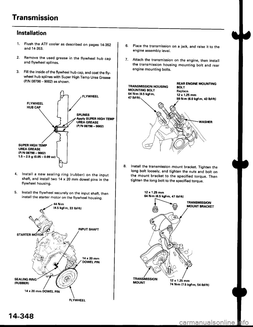
Installation
Flush the ATF cooler as described on pages 14-352and 14-353.
Remove the used grease in the flywheel hub caDand flywheel splines.
Fill the inside of the flywheel hub cap, and coat the fly-wheel hub splines with Super High Temp Urea Grease(P/N 08798 - 9002) as shown.
L
SEALING RING{RUEBER)
SPLINESApply SUPEB HlcH TEMPUREA GREASElPlN 08798 - 90O2t
SUPER HIGH TEMPUREA GREASE(P/N 08798 - !)00211.5-2.5 g 10.05-0.t9 oz)
Install a new sealing ring (rubber) on the inoutshaft, and install two '14 x 20 mm dowel Dins in theflywheel housing.
Install the flywheel securely on the input shaft, theninstallthe starter motor on the flywheel housing.
4,1Nmla.5 kgt.m, 33 tbt.ft)
INPUT SHAFT
STARTER
l4 x 20 mm DOWEL ptN
.4;i "lrj
,i rr,"r., ., a
14-348
FLYWHEEL
MOUI{T74 N.m (7.5 tstm,5a tbtftt
6. Place the transmission on s jack, and raise it to theengine assembly level.
7. Anach the transmission on the engine, then installthe transmission housing mounting bolt and rearengine mounting bolts.
TRANSMISSION HOUSINGMOUNTING BOIT6,1 N.m 16.5 kgl.m,47 tbtttl59 Nrn {6.0 kgl.m. ,€ lbt ftl
WASHER
lnstall the transmission mount bracket. Tighten thelong bolt loosely, and tighten the nuts and bott onthe mount bracket to the specified torque. Thentighten the long bolt to the specified torque.
REAR ENGINE MOUNTINGBOLTReplace.12 x 1.25 mm
12x 1.25 mn6,r N'm 16.5 kgtm,47 tbtftl
l-".--..-,^
G\V
TRANSMISSONMOUNT BRACKET
12 x 1.25 mn
Page 1025 of 2189

l.
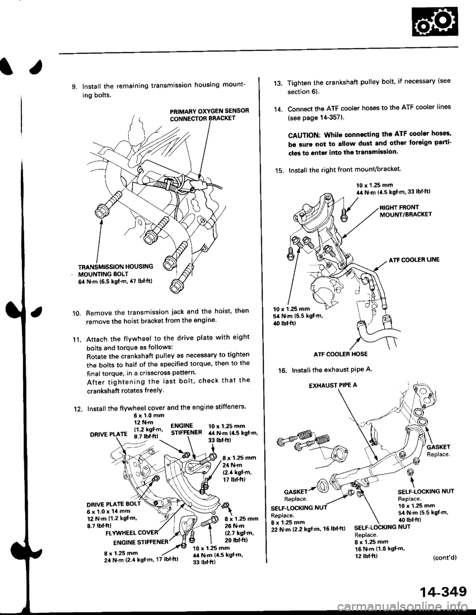
9. Install the remaining transmission housing mount-
ing bolts.
PRIMARY OXYGEN SENSOR
Remove the transmission jack and the hoist. then
remove the hoist bracket from the engine'
Attach the flvwheel to the drive plate with eight
bolts and torque as follows:
Rotate the crankshaft pulley as necessary to tighten
rhe bolts to half of the specified torque, then to the
final torque, in a crisscross pattern.
After tightening the last bolt. check that the
crankshaft rotates freelY.
10.
11.
12. Install the flywheel cover and the engine stiffeners
DRIVE
6xl.0mm12 N.m
- l12 kgf'm'rE 8.7 tbf.ftl
ENGINESTIFfENEB10 x 1.25 mmart N.m la.s kgt.m,33 tbtftt
8 x 1.25 mm24 N.m(2.1 kgf'm,17 tbt.ftt
DRIVE PI.ATE BOLT
6x1.0x14mm12 N.m {1.2 kgt m.
8.7 lbf,ftl8 x 1.25 mm26 N.m
12.7 kqfin,20 rbt'ftlFLYUTHEEL
ENGINE STIFFENER
8 x 1.25 mm10 x 1.25 mmr,a N.m {4,5 kgf m,
33 tbf.ftl
TRANSMISSION HOUSING
MOUNNNG BOLT
6il N.m {6.5 kgf.m, 47 lbf'ftl
24 N.m (2.4 kgt'm, '17 lbf'ftl
22 N.m t2.2 kgl m, 16lbf'ftl
14-349
13.
14.
Tighten the crankshaft pulley bolt, if necessary (see
section 6).
Connect the ATF cooler hoses to the ATF cooler lines
(see page 14-357).
CAUTION: Whilo connecting the ATF cooltr hGes,
b€ sure not lo allow dust and other loreign parti-
cles to entg. into the transmission.
15. Installthe right front mounvbracket'
10 x 1.25 mm
a,r N.m {4.5 kgf'm,33 lbt ftl
RIGHT FRONTMOUNT/BRACKET
ATF COOLER LINE
10 x 1 .25 mm54 N.m {5.5 kgt'm,
4{) tbl.ftt
ATF COOI,TR HOSE
16. Installthe exhaust PiPe A.
EXHAUST PIPE A
GASKETReplace.
@
\SELF.LOCKING NUTReplace.10 x 1.25 mm5/a N.m {5.5 kgt m,irc lbf.ft)
(cont'dl
*s$o
oor*rr-@Replace.
SELF.LOCKINGReplace.8 x 1.25 mmSELF.LOCKING NUT
Replace.8 x 1.25 mm16 N.m {1.6 kgl'm,12 tbl.ftt
Page 1070 of 2189

Steering Gearbox
Installation (cont'dl
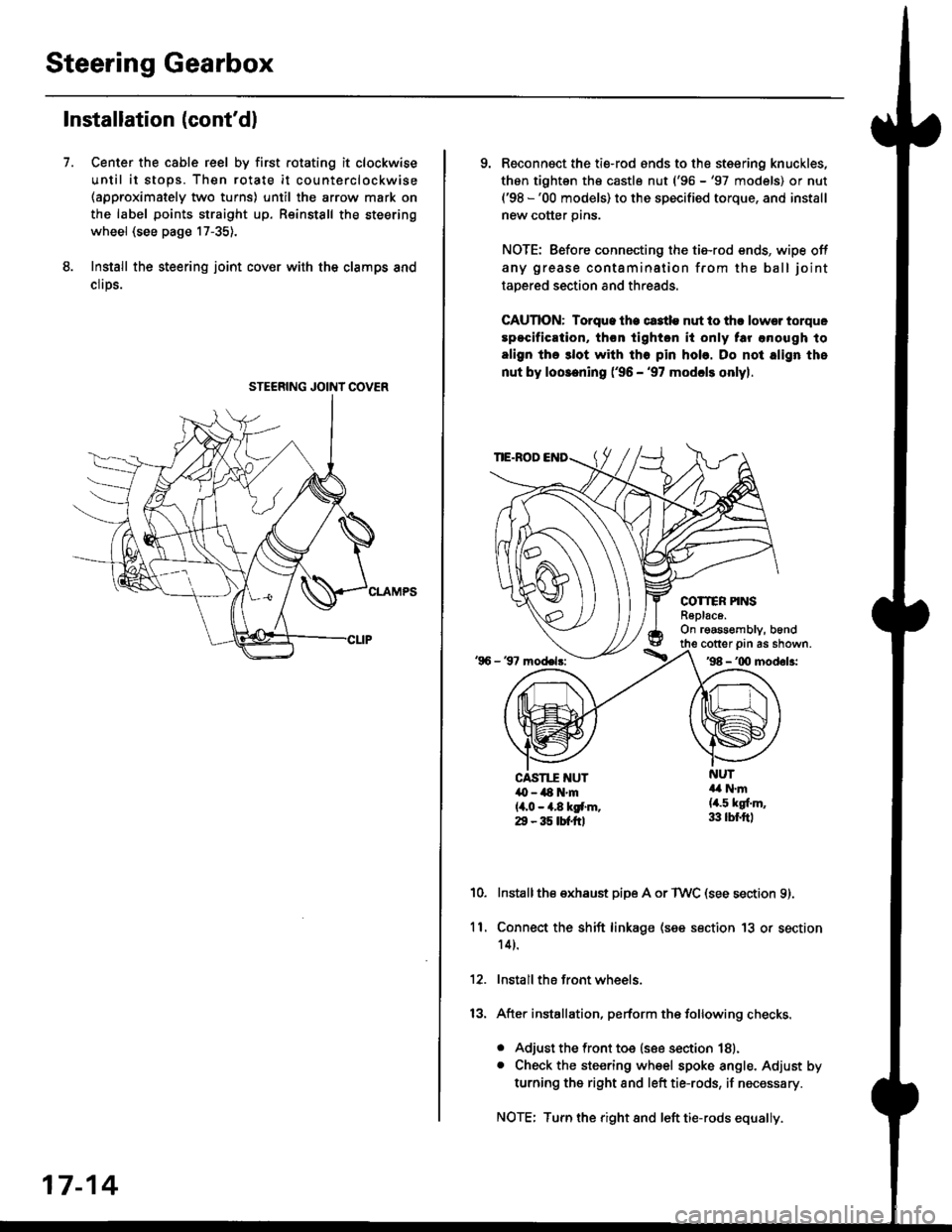
Center the cable reel by first rotating it clockwise
until it stops. Then rotate it counterclockwise(approximately two turns) until the arrow mark on
the label points straight up. Reinstall the steering
wheel (see page 17-35).
Install the steering joint cov€r with the clamps and
clrps.
7.
STEERING JOINI COVER
17-14
9. Reconnsct the ti€-rod ends to the steering knuckles,
thon tightsn th€ castle nut ('96 -'97 models) or nut('98 -'00 models) to the specified torque, and install
new cotter pins.
NOTE: Before connecting the tie-rod ends, wipe off
any grease contamination from the ball joint
tapered section and threads.
CAUTION: Torque lhe ct3tle nut to thr lowsr torque
spocification, th€n tighton it only tar anough to
align the 3lot with tho pin hob. Do not align the
nut by loosening ('96 - '97 modcls onlyl.
TIE.ROD
COTTER PINSR6plac6.On rgassombly, b6nd
'96 - 37 model3:
cotter prn as shown.'98 - '00 modol3:
NUT4a N.m(4.5 kgf.m,33 lbr.ftl
CAST1T NUT,O - ilt N'm{4,0 - 4.8 kgf.m.29 - 35 tbtftl
10.Installthe exhaust pipe A or TWC (see section 9).
Connect the shift linkage (see section 13 or section
14).
Install the front wheels.
After installation, perform the following checks.
. Adjust the front toe (see section 18).. Check the steering wheel spoke angle. Adjust by
turning the right and left tie-rods, if necessary.
NOTE: Turn the right and left tie-rods equally.
ll.
Page 1118 of 2189

Steering Gearbox
Reassembly (cont'd)
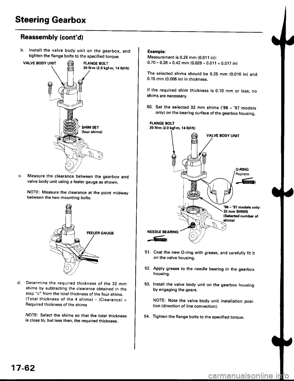
b. Install the valve body unit on the gearbox, andtighten the flange bolts to the specified torque.
VALVE BODY UNTTFLANGE BOLT20 N.m {2.0 ksl.m, 14lbI.ftl
Measure the clearance between the gearbox andvalve body unit using a feeler gauge as shown.
NOTE: Measure the clearance at the point midwaybetween the two mounting bolts.
Determine the required thickness of the 32 mmshims by subtracting the clearance obtained in thestep "c" from the total thickness of the four shims.(Total thickness of the 4 shims) - (Clearance) =
Required thickness of the shims
NOTE: Select the shims so that the total thicknessis close to. but less than, the required thickness,
17-62
54.
Example:
Measurement is 0.28 mm (0.011 in):0.70 - O.28 = 0.42 mm (0.028 - 0.011 = O.Ot7 inl
The selected shims should be 0.28 mm lO.OtO in) and0.15 mm {0.006 in} in thickness.
lf the r€quired shim thickness is 0.10 mm or less, noshims are necessarv.
50. Sot the selected 32 mm shims (,96 - ,97 modelsonly) on the bearing surface ofthe gearbox housing.
FLANGE BOLT20 N.m 12.0 ksf.m, 1l lbtftl
VALVE BODY UNIT
'96 - 37 modsl3 only:32 mm SHIMS{S.loctod numb.r of3him!l
Coat ths new O-ring with grease, and carefully fit iton the valve housing.
Apply grease to the needle bearing in the gearboxhousing.
Install the valve body unit on the gearbox housingby engaging the g€ars.
NOTE: Note the valve body unit installation posi-
tion (direction of line connection).
Tighten the flange bolts to the specified torque.
O-RINGReplace.
-A-l
NEEDLE BEARING
-R1
51.
EA