1997 HONDA CIVIC Vacuum
[x] Cancel search: VacuumPage 386 of 2189

Manifold Absolute Pressure {MAP} Sensor
('96 - 98 Models,'99 - 00 D16Y5 engine with M/T)
I
The scan tool indicates Diagnostic Trouble Code (DTC) PO107: A low voltage (high vacuum) problem in the
Manifold Absolute Pressure (MAP) sensor.
MAP SENSOR 3P CONNECTOR (C111)
vccr(YEL/BEDI
Wire side of female terminals
(D16Y5 engine (with
cw))T
YES
(cont'd)
11-117
Tho MIL has been roport€d on.
DTC P0107 is storod.
Problam verification:1. Turn the ignition switch ON (ll).
2. Check the MAP with the scan
lool.
lntormittont failuro, sYatgm ia OK
al thb timo. Chock lor Pool con_
noqtiona or looso wirca at C111
{MAP !6nsor) ond ECM/PCM.
ls approx. 101 kPa (760 mmHg,
30 in.Hg) indicated?
Chock for an opon in wiJe (VCCI
lino):1. Turn the ignition switch OFF.
2. Disconnect the MAP sensor
3. Turn the ignition switch ON (ll).
4. Measure voltage between the
MAP sensor connector No l
terminal and No 2 terminal
Ropair open in tho wit b€twocn
ECM/PCM (Dill tnd MAP !enso].ls there approx. 5 V?
Check for .n open or ahort in the
MAP 3€naor:Check the MAP with the scan
tool.
ls approx. 2 kPa (15 mmHg,
0.6 in.Hg) or less indicated?
Chsck to. a short in the TCM:
1. Turn the ignition switch OFF.
2. Disconnect the 22P connectorfrom the TCM.3. Turn the ignition switch ON
0r).4. check the MAP with the scan
tool.
(To page 11-118)
Page 388 of 2189

|'Manifold Absolute Pressure (MAP) Sensor
(;gg - OO Models except Dl6Y5 engine with M/T)
The scan tool indicates Diagnostrc Trouble Code (DTC) PO1O7: A low input (high vacuuml problem in the
Manifold Absolute Pressure (MAP) sensor'
The MAp sensor converts manifold absolute pressure into electrical signals and inputs the ECM/PCM'
OUTPUTVOLTAGE
lvl3.5
3.0
2.5
2.0
1.5
1.0
0.5
0(in.Hgl GAUGEREAOING(mmHgllq, 2oo 3q, (x, 5q) 6q) 700
MAP SENSOR 3P CONNECTOR IC114)
vccltYEL/RED)
Wire sido of fomalg tormin6ls
.-l
- The MIL h'3 been reported on- OTC P0107 b stor€d.
Problem verilication:
1. Turn the ignition switch ON {ll)
2. check the N4AP with the scan
tool.
lntermittent failuro, 3Ystom is OK
at this time. Ch€ck for Poor con'
nection3 or loose wiros at C111
IMAP sonsorl and ECM/PCM.
ls approx. 101 kPa (760 mmHg,
30 in.Hg)indicated?
Ch.ck for an opcn in wit. {vCC1
linel:1. Turn the ignition switch OFF
2. Disconnect the MAP sensor
connector.3. Turn the ignition switch ON (ll).
4. Measure voltage between the
MAP sensor connector No. 1
terminal and No 2 terminal
Repair opsn in the wirg botween
ECM/PCM (C19) rnd MAP seGor.ls there approx. 5 V?
(To page 11-120)
{cont'd)
1 1-1 19
Page 390 of 2189

!Manifold Absolute Pressure (MAPI Sensor -
i;idlga lil;dels,'99 - 00 Dl6Y5 ensine with M/T)
ll
The scan tool indicates Diagnostrc Trouble code (DTC) Po108: A high voltage (low vacuum) problem in the
Manifold Absolute Pressure (MAP) sensor.
MAP SENSOR 3P CONNECTOR ICl11}
MAPIRED/GRNI
JUMPER WIRE
Wire side ol female terminals
vcclIYEL/RED)
ECM/PCM CONNECTOR D (16PI
MAP(RED/GRN)
sG1(GRN/WHT)
Wire side of female terminals
(cont'd)
11-121
The MIL has been reported on
OTC m108 is stolod.
Problem vetitication:
1. Start the engine. Hold the
engine at 3,000 rPm with no
load (in Park or neutral) until
the radiator fan comes on, then
let it idle.
2. Check the MAP with the scan
tool.
lntormittent lailure, sFtom k OK
.t thb time. Chock lor Poor con'
nections or loorg wires at Cll'l
|MAP sensorl snd ECM/PCM.
ls 101 kPa (760 mmHg,30 0 in.Hg)
or higher indicated?
Check tor an open in the MAP
36nSOt:1. Turn the ignition switch OFF
2. Disconnect the MAP sensor
3P connector.3. Install a jumper wire betlveen
the MAP sensor 3P connector
terminals No 3and No 2.
4. Turn the ignition switch ON (ll).
5. Check the MAP with the scan
tool.
ls 101 kPa (760 mmHg, 30 0 in.Hg)
or higher indicated?
Check for an open in wire (SG1
line):1. Remove the iumper wire.
2. Measure voltage between the
MAP sensor 3P connector te.
minals No. 1 and No 2
Rapai. open in the wito batwoen
ECM/PCM (D12) .nd MAP !en.or.ls there approx. 5 V?
Check for an oPon in the wiie
(MAP linel:1. Turn the ignition switch OFF.
2. Connect the ECM/PCM con-
nector terminals D3 and D12
with a iumPer wire.
3. Turn the ignition switch ON (ll).
4. Check the MAP with the scan
tool.
Repair opon in the wiles bstlt oon
ECM/PCM (D3l and MAP 3oGor.ls 101 kPa (760 mmHg, 30 0 in.Hg)
or higher indicated?
Substituto a known'good ECM/
PCM and rochock. ll normal MAP
is indicated, replace tho original
ECM/PCM.
JUMPER WIRE
lr,
Page 391 of 2189

PGM-FI System
Manifold Absolute Pressure (MAPI Sensor
11-122
('99 - 00 Models except D16YS engine with M/T) (contd)
The scan tool indicates Diagnostic Trouble Code (DTC) P0108: A high voltage flow vacuum) problem in theManifold Absolute Pfessure (MAp) sensor,
MAP SENSOR 3P CONNECTOR (C111I
MAPIRED/GRNI
Wire side of female terminals
vcclIYEL/RED)
ECM/PCM CONNECTOR C (31PI
JUMPER WIRE
Wire side of female terminals
Tho MIL has boon rcDortod on.DTC ml 08 b stolod.
Problem verification:'1. Start the engine. Hold theengine at 3,000 rpm with noload (in Park or neutral) untilthe radiator fan comes on, thenlet it idle.2. Check the MAP with the scantoot,
Intormittent f.ilu.e, rystom is OXat thi! time. Chock tor poor con-n6ction3 or looso wirea at C111(MAP 3en.or) and tho ECM/PC-M.
ls 101 kPa (760 mmHg.30in.Hg) or higher indicated?
Check for an open in the MAPaon5('r:1. Turn the ignalion switch OFF.2. Disconnect the MAP sensor3P connector.3. Install a jumper wire betwesnthe MAP sensor 3P conn6ctorterminals No.3 and No.2.4. Turn the ignition switch ON {ll).5. Check the MAP with the scantool.
ls 101 kPa (760 mmHg, 30in.Hg) or higher indicated?
Check fo. an opcn in wiro (SGlline):1. Removo the jumper wire.2. Measure voltage between theMAP sonsor 3P connector terminals No. 1 and No.2.
Roprir opon in tha wiJo bctwoenthc ECM/FCM (C7l rnd the MApsonln t.
ls there approx. 5 V?
Chsck for an open in tho wi.e{MAP lino}:1. Turn the ignition switch OFF.2. Install a jumper wire on theECM/PCM connectors betweenC7 and C17.3. Turn the ignition switch ON (ll).4. Check the MAP with the scantool,
Repair op€n in the wir6a bstwoontho ECM/FCM (C171 and rh6 MApscnltoa.
ls 101 kPa (760 mmHg, 30in.Hg) or higher indicated?
Substituto a known-good ECM/PCM and rechcck, It normal MAPis indiceted. r.place tho originalECM/PCM.
JUMPER WIRE
--
Page 434 of 2189

t
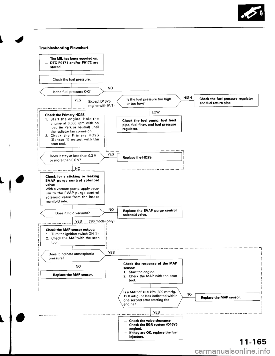
Troubleshooting Flowchart
'l
NO
a-,-:- -
YES
- The MIL ha3 b€on rePorled on.- DTC P0171 a^dlot P0172 arc
stored,
is the fuel pressure OK?
Check the fuel pt€ssure regulator
and fusl re{urn pipe.ls the fuel pressure too high
ortoo low?
Check the Primary HO2S:
1. Start the engine. Hold the
engine at 3,000 rpm with no
Ioad (in Park or neutral) until
the radiator Ian comes on
2. Check the Primary HO2S(Sensor 1) output with the
scan tool,
Check the tu6l pump. fuel leedpipe, fu€l fiher, and Iuel Pressureregulator.
Does it stay at less than 0.3 V
or more than 0.6 V?
Check lor a sticking or leaking
EVAP purge control solenoid
With a vacuum PumP, aPPIY vacu-
um to the EVAP purge control
solenoid valve from the intake
manifold side.
Does it hold vacuum?
Check the MAP sensor outputr
1. Turn the ignition switch ON (ll)
2. Check the MAP with the scan
tool.
Check th6 response of the MAP
sensoa:1. Start the engine.2. Check the MAP with the scan
tool.
ls a MAP of 40.0 kPa 1300 mmHg,12.0 inHg) or less indicated within
one second after starting the
engine?
- Check th€ valve cloarance.- Check the EGR rystem lD16Y5enginel.- lf they are OK, r€place the tueliniocto]3.
1 1-165
Page 462 of 2189

I
L
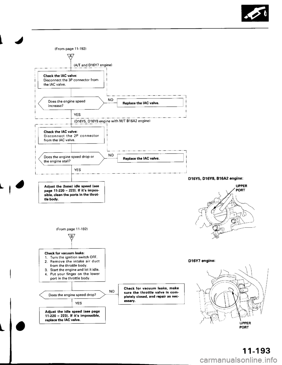
1D16Y5, D16Y8 engine with M/T 81642 engine)I
D16Y7 engine:
{From page 11-192)
Check the IAC valve:Disconnect the 3P connector from
the IAC valve.
Check the IAC valve:Disconnect the 2P connectorfrom the IAC valve.
Does the engine speed drop or
the engine stall?
Adiust the {base} idle speod (see
page 11-220 - 2231.It it's impos-
aible, clean the ports in lhe throt'
tle bodv,
(From page 11-192i
Check Ior vacuum leaks:1. Turn the ignition switch OFF.2. Remove the intake air ductfrom the throttle body.
3. Start the engine and let it idle.
4. Put your finger on the lowerpon in the th.ottle body.
Ch€ck tor vecuum loaks, m.kesure the throttle valve is com_pletaly closed, end repair as nec-Does the engine speed droP?
Adiust the idle speed (see page
11-220 - 2231. lf it's impossible,
reolace the IAC velve.UPPERPORT
1 1-1 93
Page 499 of 2189

Fuel Supply System
System Description
The fuel supply system consists of a fuel tank, in-tank
high pressure fuel pump, PGM-FI main relay, fuelfilter,
fuel pressure regulator, fuel injectors. and fuel delivery
and return lines. This system delivers pressure-regu-
lated fuel to the fuel injectors and cuts the fuel delivery
when the engine is not running.
Fuel Pressure l'96 Modelsl
Relieving
Before disconnecting fuel pipes or hoses, release pres-
sure from the system by loosening the 6 mm service
bolt on top of the fuel filter.
. Do not smoke whil6 working on the fuel system.
Kgsp opon flames or sparks away from youl work
area.
. Be sure to relieve fuel pressure while the ignition
switch is off.
1. Write down the frequencies for the radio's preset
buttons.
2. Disconnect the battery negative cable from the bat-
tery negative terminal.
3. Remove the fuelfill cap,
4. Use a box end wrench on the 6 mm service bolt at
the fuel filter while holding the special banjo bolt
with another wrench,
5. Place a rag or shop towel over the 6 mm service bolt.
6, Slowly loosen the 6 mm service bolt one complete
rurn.
. A fuel pressure gauge can be attached at the 6 mm
service bolt hole.
. Always reDlace the washer between the service
bolt and the special banjo bolt whenever the ser-
vice bolt is loosened.
. Replace all washers whenever the bolts are
removeo.
11-230
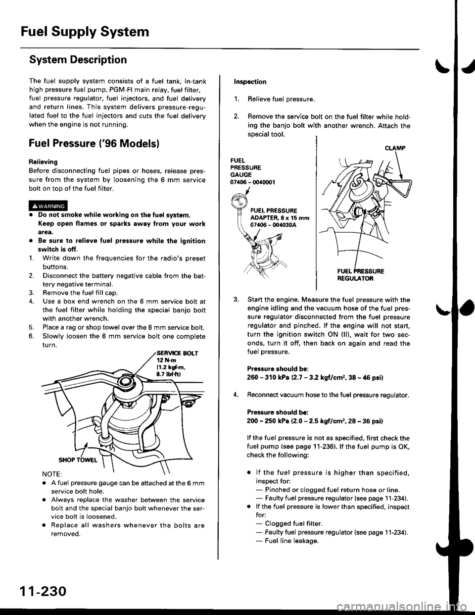
Inspoction
1. Relieve fuel pressure.
2. Remove the service bolt on the fuel filter while hold-
ing the banjo bolt with another wrench. Attach the
special tool.
FUELPRESSUREGAUGE07406 - 00ir0(x)1
Start the engine. Measure the fuel pressure with the
engine idling and the vacuum hose of the fuel pres-
sure regulator disconnected from the fuel pressure
regulator and pinched. lf the engine will not start,
turn the ignition switch ON (ll), wait for two sec-
onds, turn it off, then back on again and read the
fuel pressure.
Pr€3sure should bo:
260 - 310 kPa (2.7 - 3.2 kgt/cmr, 38 - 46 psi)
Reconnect vacuum hose to the fuel pressure regulator,
Pressure should bo:
200 - 25O kPa l2.O - 2.5 kgf/cm'�, 28 - 36 psil
lf the fuel pressure is not as specified, first check the
fuel pump {see page 11-2361. lf the fuel pump is OK,
check the following:
. lf the fuel pressure is higher than specified,
inspect for;- Pinched or clogged fuel return hose or line.- Faulty fuel pressure regulator (see page 11-234).. lf the fuel pressure is lower than specified, inspect
for:- Clogged fuelfilter.- Faulty fuel pressure regulator {see page 11-234).- Fuel line leakage.
REGULATOB
Page 500 of 2189

tJFuel Pressure {'97 and later Models)
ReliGving
Before disconnecting tuel pipes or hoses, release pres-
sure from the system by loosening the 12 mm banjo
bolt on top of the fuel filter.
@o Do not smoke whilo working on the fuel sy3lom.
Ksgp op€n flames or sparks away tlom Your work
arga.
. Be sure to relieve fuel pressule while the ignition
swhch is off.
1. Write down the frequencies for the radio's preset
buttons,
2. Disconnect the battery negative cable from the bat-
tery negative terminal.
3. Remove the fuel fill cap.
Use a box end wrench on the 12 mm banjo bolt at
the fuel filter while holding the fuel filter with anoth-
er wrench.
Place a rag or shop towel over the 12 mm banio bolt.
Slowly loosen the 12 mm banjo bolt one complete
turn.
4.
I
12 mm BAtt OBOLT33 N.m (3.i1 kgf m,25 tbf.f0
NOTE: Replace all the washers whenever the 12
mm banio bolt is loosened or removed.
Inspaqtion
1. Relieve fuel pressure.
2. Remove the 12 mm banjo bolt from the fuel filter
while holding the fuel Jilter with another wrench
Attach the special tools.
3. Start the enginethe fuel Pressure with the
engine idling and the vacuum hose of the fuel pres-
sure regulator disconnected from the fuel pressure
regulator and pinched lfthe engine will not start, turn
the ignition switch ON {ll), wait for two seconds, turn
it off, then back on again and read the fuel pressure'
Pr$3uro ehould be:
excepi 816A2 sngine:
260 - 310 kPa {2'7 - 3.2 kgf/cm" 38 - {6 Fi}
B16A2 engine:
27O -32O kPa P.8 - 3'3 kgf/cm'�, '10 - 47 psi)
4. Reconnect vacuum hoso to the fuel pressure regulator'
Pre33ure 3hould be:
except B16A2 engin€:
2OO - 250 kPa {2.0 - 2'5 kgf/cm'�, 28 - 36 psi)
B16A2 engino:
210 - 260 kPa 121 - 2.6 ksf/cm'�, 30 - 37 psi)
lf the fuel pressure is not as specified, first check the
fuel pump (see page 11-236) lfthetuel pumpisoK,
check tho following:
. lf the fuel pressure is higher than specified,
inspect for:- Pinched or clogged fuel return hose or line.
- Faulty fuel pressure regulator (see page 11-
2341.
. lf the fuel pressure is lower than specified, inspect
for:- Clogged fuel filter.
- Faulty fuel pressure regulator (see page l1-
2341.- Fuel line leakage.
FUEL PRESSUREADAPTER BOLT, 12 mm
tguxt8-PD6-0101
CLAMP
REGULATOR
11-231