1997 HONDA CIVIC Repair
[x] Cancel search: RepairPage 417 of 2189

PGM-FI System
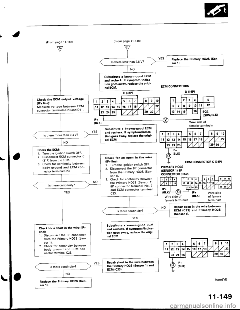
Primary Heated Oxygen Sensor (Primary HO2SI (sensor l)
(Dl6Y5 engine with M/T) (cont'd)
(From page 1l-147)(From page 11 147)
(To page 11 149)
{GRN/BLK}
(GRN/8I-K}
(To page 11-149)
11-148
Substitute a known-good ECMand rechock. tf symptom/indicr-tion goes away, replace the origi-nalECM.
Check for a short in the wire llP+lin6):1. Disconnect the 8P connectorIrom the Primary HO2S (Sen-
sor 1).2. Check tor continuity betweenbody ground and ECM connec-tor terminal C25.
Repair short in the wiro botweenthe Primarv HO2S {Sensor 1} andECM {C25}.
Replace th€ Primary HOzS {Sen-sor 11.
| 2 3ra1a9to
tl 12t516111a
p ffi;r, w''.""i0"or.I lemate lerml
ls there more than 5.0 V?check the EcM:1. Turn the ignition switch OFF.2. Disconnect the 8P connectorfrom the Primary HO2S (Sen-
sor 1).3. Turn the ignition switch ON (ll).4. Measure voltage between ECN4connector C25 and D11.
ls there more than 5.0 V?
Check the ECM input voltage llP-/vS-linel:1. Start the engine. Hold theengine at 3,000 rpm with noload (transmission in neutral)untilthe radiator fan comes on,then let it idle.2. Measure voltage between ECMconnector terminals C24 andDt1.
Subslitute a known-good ECMand rgcheck. It symptom/indica-tion goes away, repl.ce the origi-nal ECM.
ls there 2.6 2.8 V?Check th6 ECM output voltage(VS+ linel:Measure voltage between ECMconnector terminals C25 and D11.
7a9t0It 12t3t6'11ta
VS+{WHT}sG2
235
,9 ,101l12
l3'tat515
1 2i35a9t0't2'ttt5ttrl22
VS+{WHT)sG2
23
6lt9ll1315
Page 418 of 2189

(From page 11 148)(From page 11'148)
Roplac€ th€ Primary HOzS (Sen'
sor 11.ls there lessthan 2.8 V?
Substitute a known-good ECM
and recheck. lf symptom/indica'
tion goes awav, replace th€ odgi'
nalECM.
Check the ECM oulput voltage
(lP+ linel:Measure voltage between ECM
connector terminals C23 and D11
Substitute a known-good ECM
and recheck f symptom/indica-
tion goes awaY, replace the origi_
nal ECM.
ls there more than 0.4 V?
Check the ECM:1. Turn the ignition switch OFF.
2. Disconnect ECM connector C(31Plfrom the ECM.
3. Check for continuity between
body ground and ECM con-
nector terminal C23
Check fot an oPen in tha wire
llP+ linel:1. Turn the ignition switch OFF.
2. Disconnect the 8P connoctor
from the Primary HO2S (Sen-
sor'l).3. Check for continuity between
the PrimarY HO2S (Sensor 1)
8P connector terminal No. 7
and ECM connector termrnal
c23.
Repair open in the wire belween
ECM {C231 and Primary HO2S
{Sensor 11.
Substitute a known_good ECM
and r6check. lf symPlom/indica'
tion goos away, replace the odgi-
nalECM.
Check for a short in the wire llP+
line):1. Disconnect the 8P connector
from the Primary HO2S {Sen'
sor 1),2. Check for continuity between
body ground and ECM con-
nector terminal C23.
Repair short in lhe wire belween
the Primary HO2S (Sensor 'l) dnd
ECM {C23).
Replace the Primary HO2S (Sen'
sor 1).
sG2(GRN/BLKI
Wire side offemale termanals
PRIMARY HO2S(SENSOR 1l8PcoNNECTOR lC1a5l
lP+(BLK)
Wire side of
female termrnalsof femaleterminals
NO
(cont'd)
123a68910
111213141516171822
2125a30
I lP+
6) tBrK)
ECM CONNECTOR C {31P}
23a67II10
1112131l15161118,422
232a25A30
A lP+Ij/ IBLK)
11-149
Page 424 of 2189

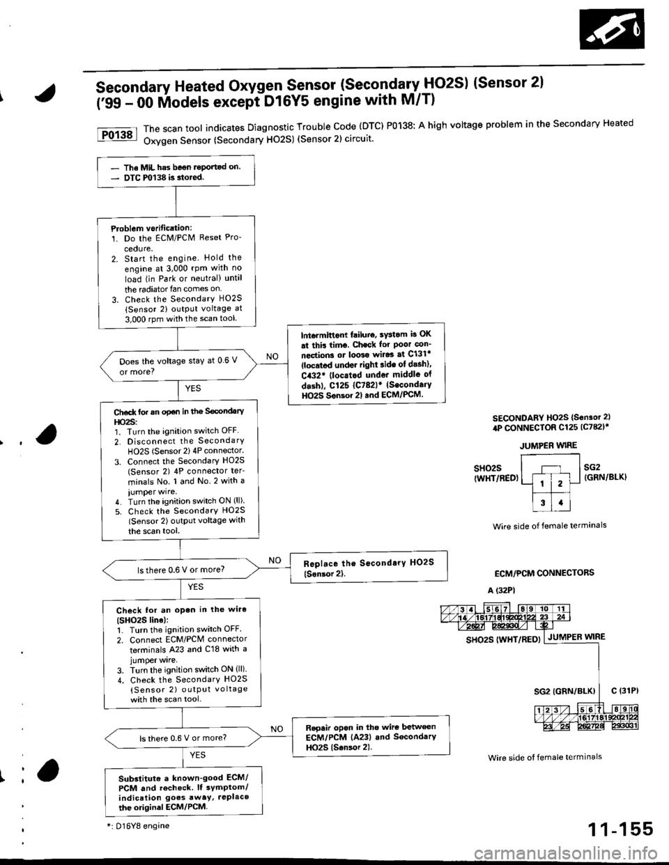
Secondary Heated Oxygen Sensor (SecondarytlO2S) (Sensor 2l
('99 - 00 lilodels except DtGYS engine with M/T)
The scan tool indicates Diagnostic Trouble code (DTC) P0138: A high voltage problem in the secondary Heated
Oxygen Sensor (Secondary H02S) (Sensor 2) circuit.
SECONDARY HO2S {S€nsot 2}
4P CONNECTOR Cl25 lc782l'
JUMPER WIRE
Ir
sH02s(WHT/RED)sG2{GRN/BLKI
Wire side of female termanals
ECM/PCM CONNECTORS
A (32P1
Wire side ot female termlnals
gs92g 111yp17p5py | .lutuPea wtne
- The MIL has beon reportod on.- DTC m138 is.tored.
Ploblem vorification:1. Do the ECM/PCN4 Reset Pro-
cedure.2. Start the engine Hold the
engine at 3,000 rpm with no
load (in Park or neutral) until
the radiator{an comes on
3. Check the SecondarY H02S(Sensor 2) output voltage at
3,000 rpm with the scan tool
lntormittont failuio, sYstom b OK
st thir timo. Check for Poor con_
nections ot loo39 wiJo3 af Cl3lr(located under right ride ot desh),
C432' (locatod undot middle of
dashl, Cl25 {C782lr (Secondaiy
HO2S Son3or 2l and ECM/PCM.
Does the voltage stay at 0 6 V
or more?
Ct€d( tor an opan in the Secondary
l|o2s:1. Turn the ignition switch OFF
2. Disconnect the SecondarY
HO2S (Sensor 2) 4P connector.
3. Connect the Secondary HO2S(Sensor 2) 4P conneclor ter_
minals No. 1 and No.2 with a
iumper wire.4. Turn the ignition switch ON (ll)
5. Check the SecondarY HO2S
lSensor 2) outptlt voltage with
the scan tool,
lsthere 0.6 V or more?
Check lor an open in the wiro(SHO2S line):1. Turn the ignition switch OFF.
2. Connect ECM/PCM connector
terminals A23 and C18 with ajumper wrre,
3. Turn the ignition switch ON (ll).
4. Check the SecondarY HO2S
{Sensor 2) outPut vo ltage
with the scan tool.
Repair opon in tho wire betwecn
ECM/PCM (A23) and SocondarY
HO2S {Sansor 2).ls there 0.6 V or more?
Substitut€ a known'good ECM/
PCM and recheck. It symptom/indication goes awey, JePlaco
the otiginel ECM/PCM
*i 016Y8 engine1 1-155
Page 427 of 2189

PGM-FI System
a
a
Heated Oxygen Sensor (HO2S) Heater
('96 - 98 Models,'99 - 00 D16Y5 engine with M/T) (cont'dl
PRIMARY HO2S {SENSOR 1I 4P CONNECTOR{c1231SECONDARY HO2S {SENSOR 2} 4PcoNNECTOR 1C125)r
r-l --'1
ll i2l
f;T;ttcl|BLK/ &)YELI Y
Wire side of fomale lerminals
SECONDARY HO2SISENSOR 2) 4P CONNECTOR{c78ilf
IBLK/WHT)
Wire side of lemale terminals
(From page 11-157)
Wire sid€ ot temale terminals
SO2HTC(BLK/WHTI* PO2SHTC{BLK/WHTI
*: P0141*+: Dl6Y8 engine
11-158
(From page 11-157)
Check tor an op6n or 3hoft in thewire {lGl lin6):Measure voltage between theHO2S 4P connector terminals No.3(D16Y8 engine: No. 4) and bodyground.- Repair open or shon in thewire between Primary HO2Slson.or 1), {No. 15 ALTERNA-TOR SP SENSORI (7.5 Al fuseand Secondary HO2S, Sonsol2t,.- Replace the No. 15 ALTERNA-TOR SP SENSOR 17.5 A) tuse.Check for an open in the wireIPO2SHTC, SO2SHTC' linel:1. Turn the ignition switch OFF.2. Reconnect the HO2S 4P con-nector.3. Disconnect the ECM/PCM con-nector A (32P).
4. Turn the ignition switch ON (ll).
5. Measure voltage between theECM,/PCM connector terminals46 and 410 {A5 and A10)*.
Ropail opan in the wire b€twoenECM/PCM lA6, A5l* and HO2S{Primary, Secondary+1.
ls there 0.1 V or less?
Substitute a known-good ECM/PCM and recheck. ll symptom/indication goes awry, repbcetho origin.l ECM/PCM.
ECM/PCM CONNECTOR A I32P)
so2sHrc ItBLK/WH0.J
pozsxtc E/
IBI-K/WHTI ^,-----{v}-|.=,|I
PG1IBLK}3u I JsTgT roll12r3t5t6Ittar920z2l 2321
25272A2i3o
Check tor a short in the wire{PO2SHTC. SO2SHTC* line):'1. Turn the ignition switch OFF.2. Disconnect the ECM/PCM con-nector A (32P1.
3. Check for continuity betweenthe ECM/PCM connector termi-nal 46 (A5)* and body ground.
Repair short in thg wire betwe€nECM/PCM lA6, A5*l .nd HO2S(P.im.ry, Socondary*).
Substitute a known-good ECM/PCM and recheck. It symptom/indicetion goes away, rophcethe original ECM/PCM.
Page 431 of 2189

PGM-FI System
I
a
a
Ch6ck the PO2SHTC circuit:1. Start engine and keep enginerpm at idle.2. At the engine wire harness,measure voltage betweenPrimary HO2S (Sensor 1) 8Pconnector terminal No. 1 terminal and body ground.
Check for an open in the wire(PG linellMeasurc voltage between PrimaryHO2S (Sensor 1) 8P connector ter-minals No. l and No.2.
ls there morethan 5 V?
Repair opon in the wi.o bEtwoonthe HO2S.nd G101 (located atth.rmonat housingl.
ls there more than 5 V?
Substitule a known-good ECM.nd .echeck. lt 3ymptom/indica-tion 906! rwry, roplace the origi-nal ECM,Check lor a short in the wire
{PO2SHTC line):1. Turn the ignition switch OFF.2. Disconnect ECM connector A(32P)trom the ECM.3. Check for continuity betweenECM connector terminal 46and body ground.
Ropair 3hort in tho wire betwoenthe ECM {46} and the Prim.ryHO2S lson3or 11.
Check for an open in the wire(PO2SHTC linel:Check for continuity betweenECM connector terminal 46 andthe Primary HO2S (Sensor 1)8Pconnector terminal No. 1.
Repair opsn in the wir6 botweenECM {A6} .nd the Primary HO2Slsonror 1).
Substituto a known-9ood ECMand rech6ck. lf symptom/indica-tion goes away, replace the origi-nal ECM.
Heated Oxygen Sensor (HO2S) Heater (Dl6Y5 engine with M/Tl (cont'd)
(From page 11-161)PRIMARY HO2S (SENSOR 1} 8P CONNECTOR {Cl45I
PO2SHTC{BtK/WHT)
PO2SHTCIALK/WHTI
ECM CONNECTOR
female terminals
11-162
\.
!
\
A {32P}
o
6I9l roIt
12t3l5t61't8t9a221 232a
252'2aEito,1| ---
Page 432 of 2189

The scan tool indicates Diagnostic Trouble Code (DTC) Pl167: A system malfunction in the Primary Heated
Orygen Sensor {Primary HO2S) (Sensor 1) Heater circuit
PRIMABY HO2S ISENSOR 1} 8P CONNECTOR
tc145l
ECM CONNECTOR C (31P)
- The MIL has be€n reported on.- DTC Pl167 i3 3tored.
Problem Veritication:1. Do the ECM Reset Procedure.
2. Start the engine. Hold the
engine at 3,000 mm with no
load (transmission in neutral)
until the radiator fan comes
on.Intormittont failure, system i3 OK
at thia time. Chock for Poor con_
noction3 or looso wilgt ai Cl45(Primary HO2S, Son3or 1l andECM.
ls DTC1167 indicated?
Check lor sn open in the wire(VS+ linel:1. Turn the ignition switch OFF
2. Disconnect the Primary HO2S
{Sensor 1) 8P connector.
3. Turn the ignition switch ON (ll).
4. Measure voltage betwe€n thePrimary HO2S (Sensor '1) 8P
connector terminal No 6 and
body ground.
Ch.ck the ECM:Measure voltage between the
ECM connector terminsl C25 and
body ground.
ls there more than 5 V?
Repair opon in the wite ECM (C25)
and P m.ry HO2S (S€n3or 11.ls there more than 5 V?
Replaco the Primary HO2S (Son-
sor 11.Substitute ! known-good ECM
and r6check. lf symptom/indica-tion gos6 away, r.place tho origi'
nd ECM,
,l23458910
111213t415161718
a2125a30
VS+{WHTIWire side of femaleterminals
1 1-163
Page 437 of 2189

PGM-FI System
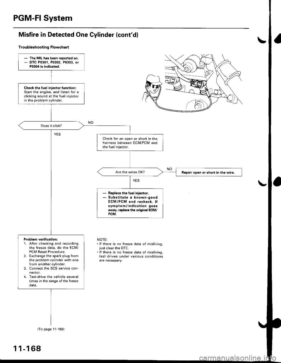
Misfire in Detected One Gylinder (cont'dl
Troubleshootin g Flowchart
NOTE:. lf there is no treeze data of misfiring,just clear the DTC.. It there is no freeze data of misfiring,test drives under various conditions
- The MIL has been reoorted on.- DTC P0301. P0302. P0303, orP030il is indicated.
Check the fuel iniecto. lunction:Stan the engine, and listen for aclicking sound at the fuel injectorin the problem cylinder.
Check for an open or short in theharness between ECM/PCM andthe fuel iniector.
Repair open or short in the wir€.
Replace the fuel iniector.Sub3titute a known-goodECM/PCM and recheck. Itsymptom/indication goesaway, replace the original ECM/PCM.
Problem verification:1. After checking and recordingthe freeze data, do the ECM/PCM Reset Procedure.2. Exchange the spark plug fromthe problem cylinder with onefrom another cylinder,3. Connect the SCS service con'nector,4. Test-drive the vehicle severaltimes in the range ofthe free2edata.
(To page 11-169)
1 1-1 68
Page 442 of 2189

(From page | 1-172)
Check fo. a sho.t in the CKP/
TDC/CYP sensor:Check for continuity to bodYground on both terminals of the
indicated senso r individually
1*see table).
Replaco the di3tributor ignition
hoGing lsee section 23).ls there continuity?
Check for an open in the wires
ICKP/TOC/CYP line3):1. Reconnect the distributor 10P
connecaor.2. Disconnect the EcM/PCM con-
nector C {31P}.3. N4easure resistance betweenthe terminals of the indicated
sensor on the ECIM/PCM con-
nector {*see tabie}.
Repair open in the indicated sen-
sor wires lrsee tablel.ls there 350 - 700 o?
Chock lor. short in the wires
ICKP/TDC/CYP lines):
Check for continuity between
body ground and ECM/PCM con-
nector terminals C2, C3 and/or C4individually.
Repai. short in the indic.ted sen_
sor wire3 ('soe tablol,ls there continuity?
Substitute e known-good ECM/PCM, and iecheck. ll sYmptom/indication goes awev, r€Place the
original ECM/PCM.
DISTRIBUTOR10P CoNNECTOR {C1201
Terminalside ofmale terminals
ECM/PCM CONNECTORS C 131P)
CI(P P TDC P CYP P(YEL)
M
CKP M(WHT)MIBLKI
Wire side offemale terminals
CYP PIYELI
(REDI
TDC P(GRN)CKP P(BLU}
t
TDC P (GRNI
11-173