1997 HONDA CIVIC keyless door lock control unit
[x] Cancel search: keyless door lock control unitPage 1481 of 2189
O
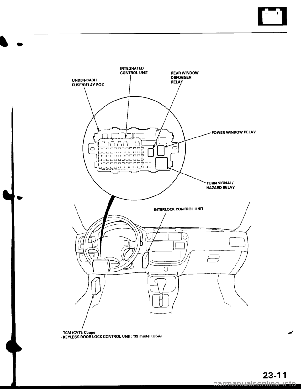
UNDER.OASHFUSE/NELAY BOX
. TCM (CVT): Coupe. KEYLESS DOOR LOCK CONTROL UNIT: '99 model {USAI
REAR WINDOWDEFOGGEB
INTERLOCK CONTROL UNIT
POWER WINDOW RELAY
oF- -=----rr Jl r c
23-11
Page 1506 of 2189
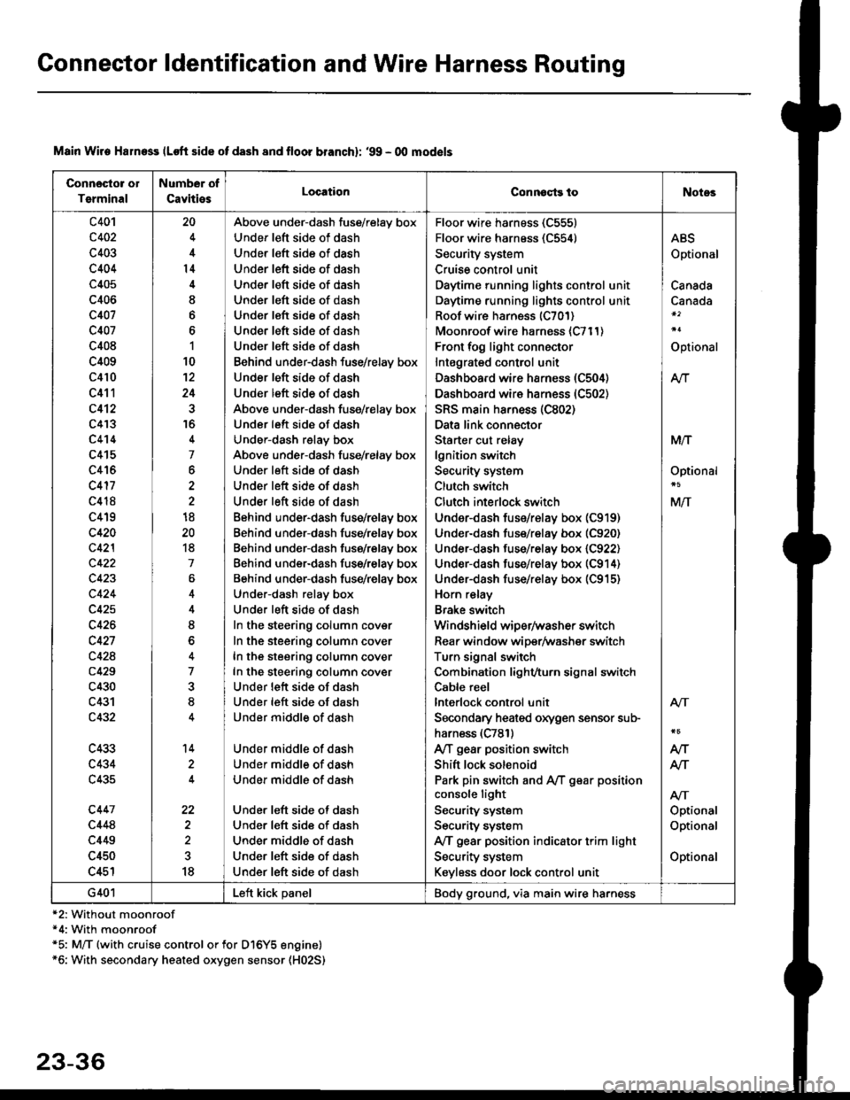
Connector ldentification and Wire Harness Routing
Connosto! ol
Tsrminal
Number of
CavitiesLocationConnoqtg toNotes
c401
c402
c403
c404
c405
c406
c407
c407
c408
c409
c410
c411
c412
c4'�I3
c4't4
c415
c416
c417
c418
c419
c420
c42l
c422
c423
c424
c425
c426
c427
c428
c429
c430
c431
c432
c433
c434
c435
c447
c448
c449
c450
c451
20
4
14
I
6
1
10
12
24
16
4
7
6
2
18
20
18
7
4
8
o
7
8
14
22
18
Above under-dash fuse/relay box
Under left side of dash
Under left side of dash
Under left side of dash
Under left side of dash
Under left side of dash
Under left side of dash
Under left side of dash
Under left side of dash
Behind under-dash fuse/relay box
Under left side of dash
Under left side of dash
Above under-dash fuse/relay box
Under left side of dash
Under-dash relay box
Above under-dash fuse/relay box
Under left side of dash
Under left side of dash
Under left side of dash
Behind under-dash fuse/relay box
Behind under-dash fuse/relay box
Behind under-dash fuse/relay box
Behind under-dash fuse/relay box
Behind under-dash fuse/relay box
Under-dash relay box
Under left side of dash
In the steering column cover
In the steering column cover
In the steering column cover
In the steering column cover
Under lett side of dash
Under left side of dash
Under middle of dash
Under middle of dash
Under middle of dash
Under middle of dash
Under left side of dash
Under left side of dash
Under middle of dash
Under left side of dash
Under left side of dash
Floor wire harness (C555)
Floor wire harness (C554)
Security system
Cruise control unit
Daytime running lights control unit
Daytime running lights control unit
Roof wire harness (C701)
Moonroof wire harness {C711)
Front fog light connector
Intagrated control unit
Dashboard wire harness (C504)
Dashboard wire harness (C502)
SRS main ha.ness (C802)
Data link connector
Starter cut relay
lgnition switch
Security system
Clutch switch
Clutch interlock switch
Under-dash fus€/relay box (C919)
Under-dash fuse/relay box (C920)
Under-dash fuse/relay box (C922)
Under-dash fuse/relay box (C914)
Under-dash fuse/relay box (C915)
Horn relay
Brake switch
Windshield wiper/washer switch
Rear window wiper/Washer switch
Turn signal switch
Combination light/turn signal switch
Cable reel
lnterlock control unit
Secondary heaied oxygen sensor sub-
harness (C781)
A/T gear position switch
Shift lock solenoid
Park pin switch and A,/T g€ar position
console light
Security system
Security system
IVT gear position indicator trim light
Security system
Keyless door lock control unit
ABS
Optional
Canada
Canada
Optional
At-|.
M/T
Optional
M/T
Atr
Optional
Optional
Optional
Atr
AIT
AJ-|.
G401Left kick panelBody ground, via main wire harness
Main Wire Halness lLoft side of dash 8nd lloor branchl: '99 - 00 mod€ls
*2: Without moonroof*4: With moonroof*5: M/T (with cruise control or for Dl6Y5 engine)*6: With secondary heated oxygen sensor (H02S)
23-36
Page 1535 of 2189
lr-
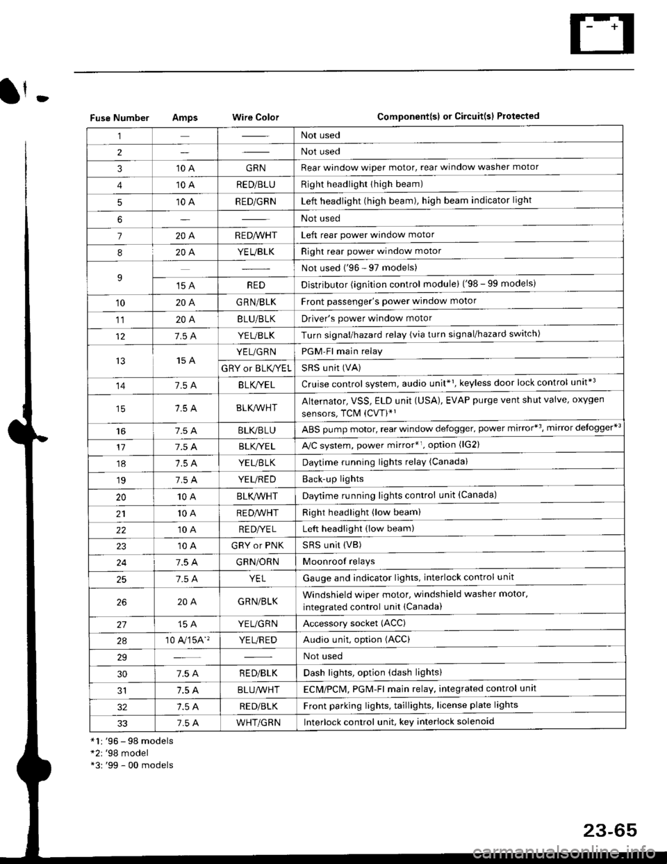
Fuse NumberAmpswire ColorComponent{sl or Circuit(sl Protected
*1r '96 - 98 models*2r '98 model*3: '99 - 00 models
,lNot used
2Not used
310 AGRNRear window wioer motor, rear window washer motor
410 ARED/BLURight headlighr thigh beam)
510 ARED/GRNLeft headlight (high beam), high beam indicator light
6Not used
7204R E D/VVHTLeft rear power window motor
820A.YEUBLKRight rear power window motor
9Not used ('96 - 97 models)
't5 AREDDistributor (ignition control module) ('98 - 99 models)
10204G RN/BLKFront passenger's power window motor
1120ABLU/BLKDriver's power window motor
127.5 AYEUBLKTurn signal/hazard relay (via turn signal/hazard switch)
t515 AYEL/GRNPGM-Fl main relay
GRY or BLK,^/ELSRS u nit (VA)
141.54B LK/YE LCruise control system, audio unit*1, keyless door lock control unit*3
BLK/lr'r'HTAlternator, VSS, ELD unit (USA), EVAP purge vent shut valve, oxygen
sensors, TCM (CVT)*'
t6BLI(,/BLUABS pump motor, rear window defogger. power mirror*3, mirror delogger*3
177.5 ABLK,/YE LA,/C system, power mirror*r. option (lG2)
18YEUBTKDaytime running lights relay (Canada)
197.5 AYEUREDBack'up lights
2010ABLK/VVHTDaytime running lights control unit (Canada)
2110 AREDA/VHTRight headlight (low beam)
2210 ARE DI/E LLeft headlight (low beam)
10 AGRY or PNKSRS UNit (VB)
247.5 AGRN/ORNMoonroof relays
257.5 AYELGauge and indicator lights. interlock control unit
204GRN/BLKWindshield wiper motor, windshield washer motor,
integrated control unit {Canada)
15 AYEL/GRNAccessory socket (ACC)
2a10 A,/'�]5A''YE L/R EDAudio unit, option (ACC)
29Not used
307.5 AR ED/BLKDash lights, option (dash lights)
1.5 ABLUA/VHTECM/PCl\4, PGM-Fl majn relay, integrated control unit
RED/BLKFront parking lights, taillights, license plate lights
337.5 AWHT/GRNlnterlock control unit. key interlock solenoid
23-65
Page 1721 of 2189
Power Door Locks
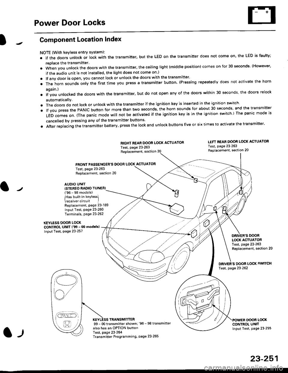
Component Location Index
NOTE (With keyless entry systeml:
. It the doors unlock or lock with the transmitter, but the LED on the transmitter does not come on, the LED is faulty;
replace the transmitter'
. when vou unlock the doors with the transmitter, the ceiling light (middle position) comes on for 30 seconds. (However,
if the audio unit is not installed, the light does not come on )
. lf any door is open, you cannot lock or unlockthe doors with the transmitter'
. The horn sounds only the first time you press a transmitter button. (Pressing repeatedly does not activate the horn
again.)
o lf vou unlocked the doors with the transmitter, but do not open any of the doors within 30 seconds, the doors relock
automatically.
. The doors do not lock or unlock with the transmitter if the ignition key is inserted in the ignition switch
. lf you press the PANIC button for more than two seconds, the horn sounds for about 30 seconds, and the transm'fer
LED comes on. (The panic mode will not be activated iJ the ignition key is in the ignition switch ) The panic mode is
cancelled by pressing any of the transmitter buttons'
o After replacing the transmitter battery, press the lock and unlock buttons five or six times to activate the transmitter'
Replacement, section 20
FRONT PASSENGER'S DOOR LOCK ACTUATOR
RIGHT REAR DOOR LOCK ACTUATOR
Test, page 23-263
I.IFT REAR DOOR LOCK ACTUATOR
Test, page 23 263Replacement, section 20
LOCK ACTUATORTest, page 23-263Replacement, section 20
ORIVER'S DOOR LOCK SWITCH
Test, page 23'262
DOOR L@XCONTROL UN]TInput Test, page 23 255
23-251
Test, page 23-263Replacement, section 20
AUDIO UNIT(STER€O RADIO TUNER)
{'96 - 98 models)
lHas built-in keylessl
eceiver circuit IReplacement, page 23-189
Input Test, page 23-260
Terminals, page 23-262
KEYLESS DOOR LOCKCONTROL UNIT l'99 - 00 modelsl
Input Test, Page 23-257
l-l
TRANSMITTER99 - 0O transmitter shown;'96 -98 transmifter
also has an OPTION buttonTest, page 23-264Transmitter Programming, page 23_265
Qi,,a/
/----
L(ru
i'.-8,-'l
/'-'6
Page 1728 of 2189
Power Door Locks
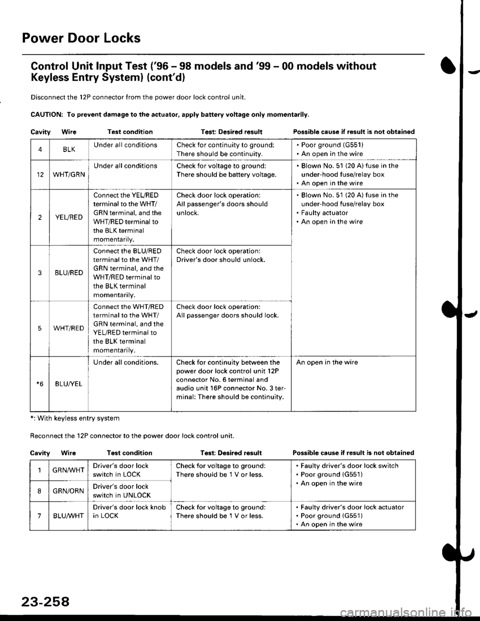
Control Unit lnput Test ('96 - 98 models and'99 - 00 models without
Keyless Entry Systeml (cont'dl
Disconnect the 12P connector from the power door lock control unit.
CAUTION: To prevsnt damage to the actuator, apply battery voltage only momentarily.
Cavity WireTest conditionTest: Desired resultPossible cause if result is nol obtained
*: With keyless entry system
Reconnect the 12P connector to the power door lock control unit.
Cavity WireTest conditionTssl: Desirsd losullPossible cause it resull b not obtained
4BLKUnder all conditionsCheck for continuity to ground:
There should be continuity.
. Poor ground (G55'l ). An open in the wire
WHT/GRN
Under all conditionsCheck for voltage to ground:
There should be battery voltage.
. Blown No. 51 (20 A)fuse in the
under-hood fuse/relay box. An open in the wire
2YEURED
Connect the YEURED
terminal to the WHT/
GRN terminal, and the
WHT/RED terminal to
the BLK terminal
momenraflty.
Check door lock operation:
All passenger's doors should
untocK.
Blown No. 51 {20 A) fuse in the
under-hood fuse/relay box
Faulty actuator
An open in the wire
3BLU/RED
Connect the BLU/RED
terminal to the WHT/
GRN terminal. and the
WHT/RED terminal to
the BLK terminal
momenraflry.
Check door lock operation:
Driver's door should unlock.
5WHT/RED
connect the WHT/RED
terminal to the WHT/
GRN terminal, and the
YEL/RED terminal to
the BLK terminal
momenrafl ty.
Check door lock operation:
All passenger doors should lock.
BLU/YEL
Under all conditions.Check for continuity between the
power door lock control unit l2P
connector No. 6 terminal and
audio unit 16P connector No. 3 ter-
minal: The.e should be continuity.
An open in the wire
GRN,ryVHTDriver's door lock
switch in LOCK
Check for voltage to ground:
There should be 1 V or less.
Faulty driver's door lock switch
Poor ground {G551)
An open in the wire
8GRN/ORNDriver's door lock
switch in UNLOCK
7BLUA/VHT
Driver's door lock knob
in LOCK
Check for voltage to ground:
There should be 1 V or less.
Faulty driver's door lock actuator
Poor ground {G551)
An open in the wire
Page 1729 of 2189
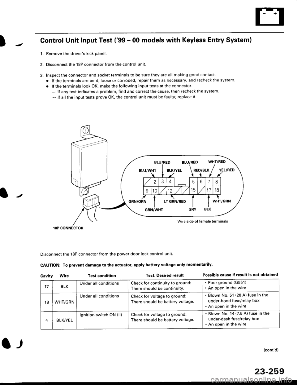
)Control Unit Input Test ('99 - 00 models with Keyless Entry System)
1.Remove the driver's kick panel.
Disconnect the 18P connector from the control unit.
Inspect the connector and socket terminals to be sure they are all making good contacl.
. lf the terminals are bent, loose or corroded, repair them as necessary, and recheck the system
. lf the terminals look OK, make rhe following input tests at the connector.
- lf anv test indicates a problem, find and correct the cause, then recheck ihe system
- lf all the input tests prove OK, the control unit must be faulty; replace it
Wire side oI female terminals
Disconnect the 18P connector from the power door lock control unit.
CAUTION: To provent damage to the actuator, apply battery Yoltage only momentarily.
Cavity Wir€ Test conditionTest: Desired resultPossible cause if result is not obtained
BLK/YELRED/SLK
25618
910/,'2 ,/
'151718
LTWHT
17BLKUnder all conditionsCheck for contlnuity to ground:
There should be continuity.
. Poor ground (G551)
. An open in the wire
t8WHT/GRN
Under all conditionsCheck tor voltage to ground:
There should be battery voltage.
. Blown No. 5'1 (20 A) luse in the
under-hood tuse/relay box
. An open in the wire
4B LK/YEL
lgnition switch ON (ll)check for voltage to ground:
There should be battery voltage.
Blown No. l4 (7.5 A) fuse in the
under-dash fuse/relay box
An open in the wire
(cont'd)
23-259
l-r
Page 1730 of 2189
Power Door Locks
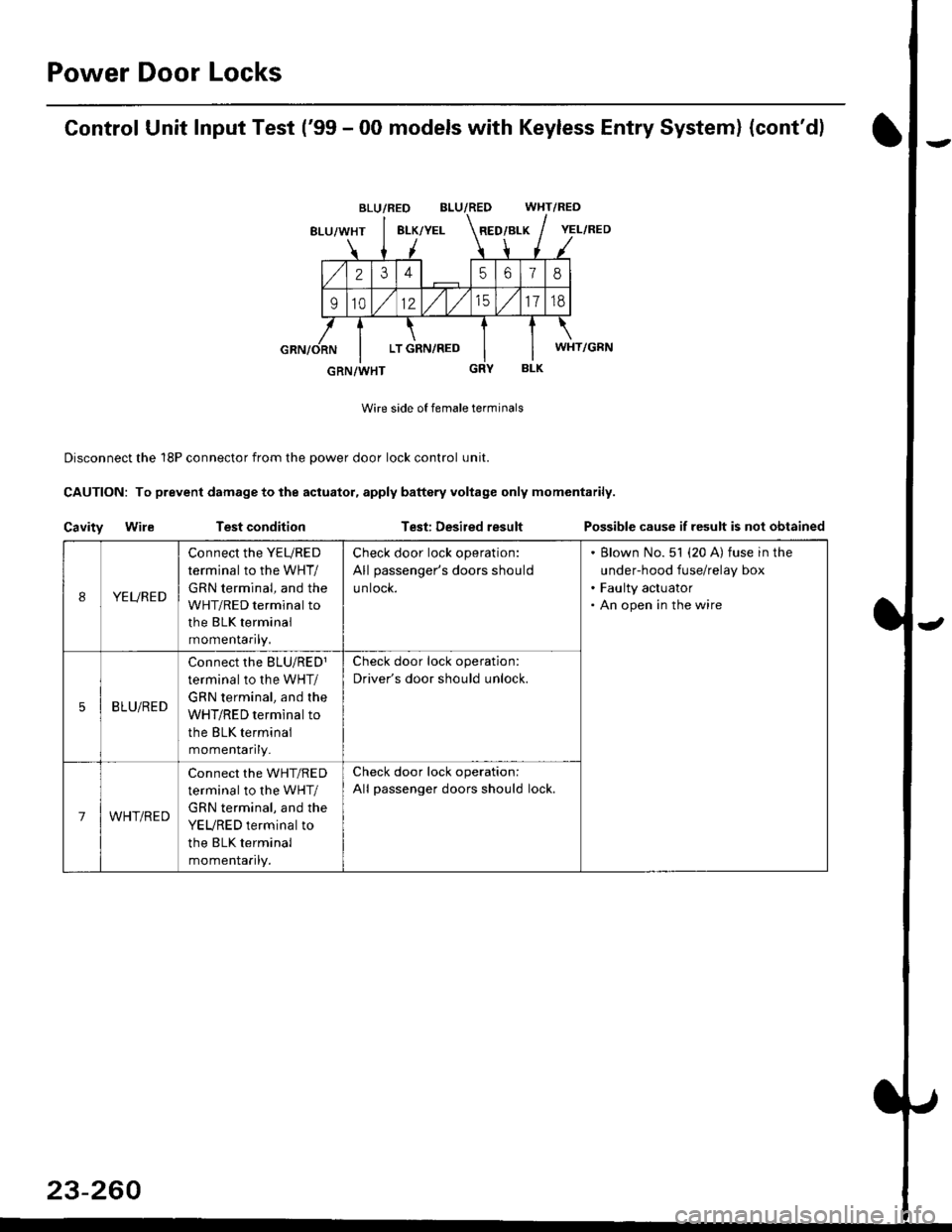
Control Unit Input Test ('99 - 00 models with Keyless Entry System) (cont'd)
BLU/RED WHT/RED
8LU/WHT8LK/YELRED/BLK
2345618
91012/t/t517td
LT GRN,/RED
BLK
Wire side of female terminals
Disconnect the 18P connector from the oower door lock control unit.
CAUTION: To prevent damage to the actuator, apply baftery voltage only momentarily.
Cavity WileTest conditionTest: Desired resultPossible cause if result is not obtained
BLU/RED
YEL/RED
WHT/GRN
GRN/WHT
IYEURED
Connect the YEURED
terminal to the WHT/
GRN terminal, and the
WHT/RED terminal to
the BLK terminal
momenraflty,
Check door lock operation:
All passenger's doors should
untocK.
Blown No. 51 (20 A) fuse in the
under-hood fuse/relay box
Faulty actuator
An open in the wire
5BLU/RED
Connect rhe BLU/RED1
terminal to the WHT/
GRN terminal, and the
WHT/RED terminal to
the BLK terminal
momenlaflry_
Check door lock operation:
Driver's door should unlock.
7WHT/RED
Connect the WHT/RED
terminal to the WHT/
GRN terminal, and the
YEURED terminal to
the BLK terminal
momenlaflry.
Check door lock operation:
All passenger doors should lock.
23-260
Page 1732 of 2189
Power Door Locks
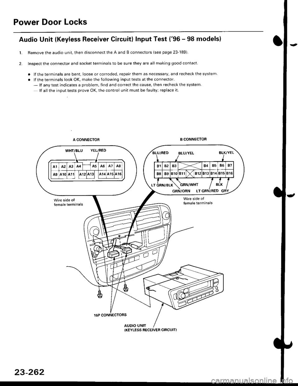
Audio Unit {Keyless Receiver Circuitl Input Test ('96 - 98 models}
Remove the audio unit, then disconnect the A and B connectors (see page 23-189).
Inspect the connector and socket terminals to be sure they are all making good contact
. lf the terminals are bent, loose or corroded, repair them as necessary, and recheck the system
. lf the terminals look OK, make the following input tests at the connector.
- lf anv test indicates a problem, find and correct the cause, then recheck the system
lf all the inout tests prove OK, the control unit must be faulty; replace it.
A CONNECTOBB CONNECTOR
16P CONNECTORS
AUDIO UNIT
L
2.
WHT/BLU YEL/RED
{KEYLESS RECEIVER CIRCUIT}
23-262