Page 1240 of 2189
Doors
Door Panel Replacement
NOTE: Take care not to scratch the door panel and otherparts.
1. Remove:
. Inner handle (see page 20-9)
. Regulator handle (see page 20-4)
2. Remove the door grip cover, then remove the screws.
>: Screw location3.2
20-10
3. Release the clips that hold the door panel. Removethe door panel by pulling it upward.
NOTE: Remove the door panel with as little bend-ang as possible to avoid creasing or breaking it.
,L12 mm(0.47 in.) T-TRIM PADREMOVER(Commercially
available)Snap-on#4177, orequival€nt
4
lNlrRrM PAD---_Jl iREMOVER .I+ ]
F/
rt{-
lmm l---4 ,nu"(o.o1in.l 1 f- -l45 mm '
11.77 in.l
>rClip locations, T
4. Installation is the reverse of the removal Drocedure.
Page 1285 of 2189
L
L
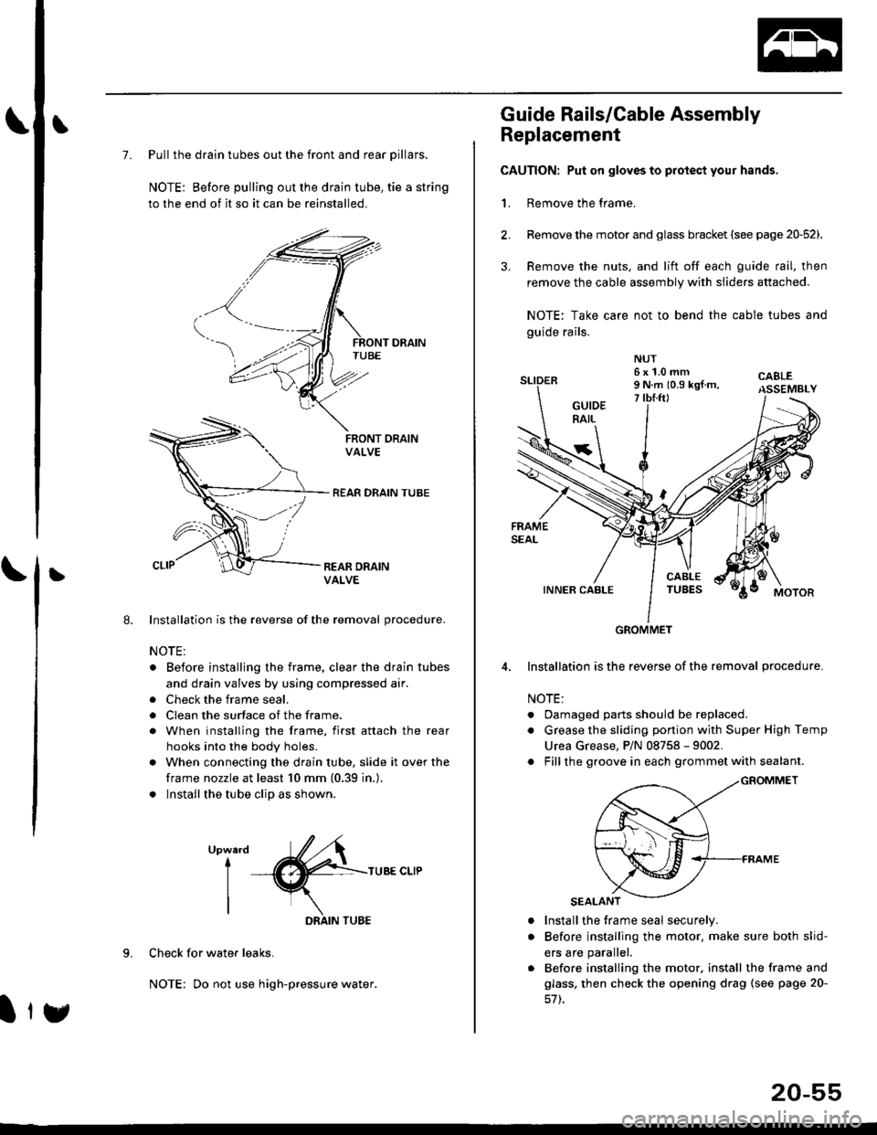
7. Pull the drain tubes out the front and rear pillars.
NOTE: Before pulling out the drain tube, tie a string
to the end of it so it can be reinstalled.
Installation is the reverse of the removal procedure.
NOTE:
. Before installjng the frame, clear the drain tubes
and drain valves by using compressed air.
. Check the frame seal.
. Clean the surface of the frame.
. When installing the frame, first attach the rear
hooks into the body holes.
. When connecting the drain tube, slide it over the
frame nozzle at least 10 mm (0.39 in.).
. Install the tube clip as shown.
UpwardI
I
I
TUBE CLIP
Check for water leaks.
NOTE: Do not use high-pressure water.
DRAIN TUBE
Ity
20-55
Guide Rails/Cable Assembly
Replacement
CAUTION: Put on gloves to protect your hands,
1. Remove the frame.
Remove the motor and glass bracket (see page 20-52).
Remove the nuts, and lift off each guide rail, then
remove the cable assembly with sliders attached.
NOTE: Take care not to bend the cable tubes and
guide rails.
Installation is the reverse of the removal procedure.
NOTE:
. Oamaged parts should be replaced.
. Grease the sliding portion with Super High Temp
Urea Grease, P/N 08758 - 9002.
. Fillthe groove in each grommet with sealant.
a
a
Install the frame seal securely.
Before installing the motor. make sure both slid-
ers are parallel.
Before installing the motor. install the frame and
glass, then check the opening drag (see page 20-
GROMMET
Page 1288 of 2189
Interior
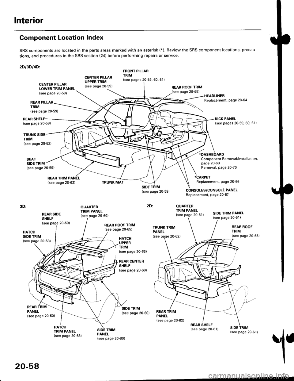
Component Location Index
SRS comDonents are located jn the parts areas marked with an asterisk (*). Review the SRS component locations, precau
tions, and procedures in the SRS section {24) before performing repairs or service.
2Dl3Dl4Dl
CENTER PILLARUPPER TRIM{see page 20 591
FRONT PILLARTRIM{see pages 20 59,60,61)
REAR PILLARTRIM
TRUNKTRIM(see page 20-62)
SEATSIDE TRIM{see page 20-59)
{see page 20 59}
CENTER PILLARLOWER TRIM PANEL(see page 20-59)
REAR ROOF TRIM(see page 20-65)
:
OUARTERTRIM PANEL
{see page 20'61)
HEADLINERReplacement, Page 20'64
*OASHBOARO
Component Removal/lnstallation,page 20 68
REARlsee page 20 59)
REAR TRIM PANEL
lsee page 20-62)
Removal, page 20-70
*CARPET
Replacement, page 20 66
PANELReplacement, page 20-67
3D:
REAR SIDESHEI-F(see page 20-60)
OUARTERTRIM PANEL(see page 20-60)SIDE TRIM PANEL(see page 20-6'l)
2Dl
HATCHSIDE TRIM(see pase 20 63)
REAR ROOF TRIM(see page 20 65)REAR ROOFTFIM(see page 20'65)HATCHUPPERTRIMlsee page 20 63)
CENTERSHELFlsee page 20 60)
REARPANELlsee page 20 60)
SIDE TRIM{see page 20 60)REARPANEL(see page 20 62)
1
HATCHTRIM PANEL(see page 20-63)
SIDE TRIMPANEL(see page 20-60)
20-54
Page 1297 of 2189
Consoles/Console Panel
Replacement
NoTE:Takecarenottoscratchthefrontandrealconso|es,frontseatandre|atedparts.
Disassemble in numbered sequence
>: Screw locationsa>,8 B>,4>: Clip locationsA>,2 B>.2
' nnffir
:__)
"=)
:)
::r_l REAB CONSoLE(with armrest)
lnstallation is the reverse of the removal procedure
NOTE:
. lf necessary, replace any damaged clips.
. Make sure the wire harnesses are not pinched.
. Make sure the connector is connected properly.
€] FRONT CONSOLERemove the shift lever knob (M/T)
{.
I
I
20-67
Page 1338 of 2189
Opener Cables
Replacement
NOTE:
t When removing the clips. use a clip remover.. Take care not to bend the opener cables.
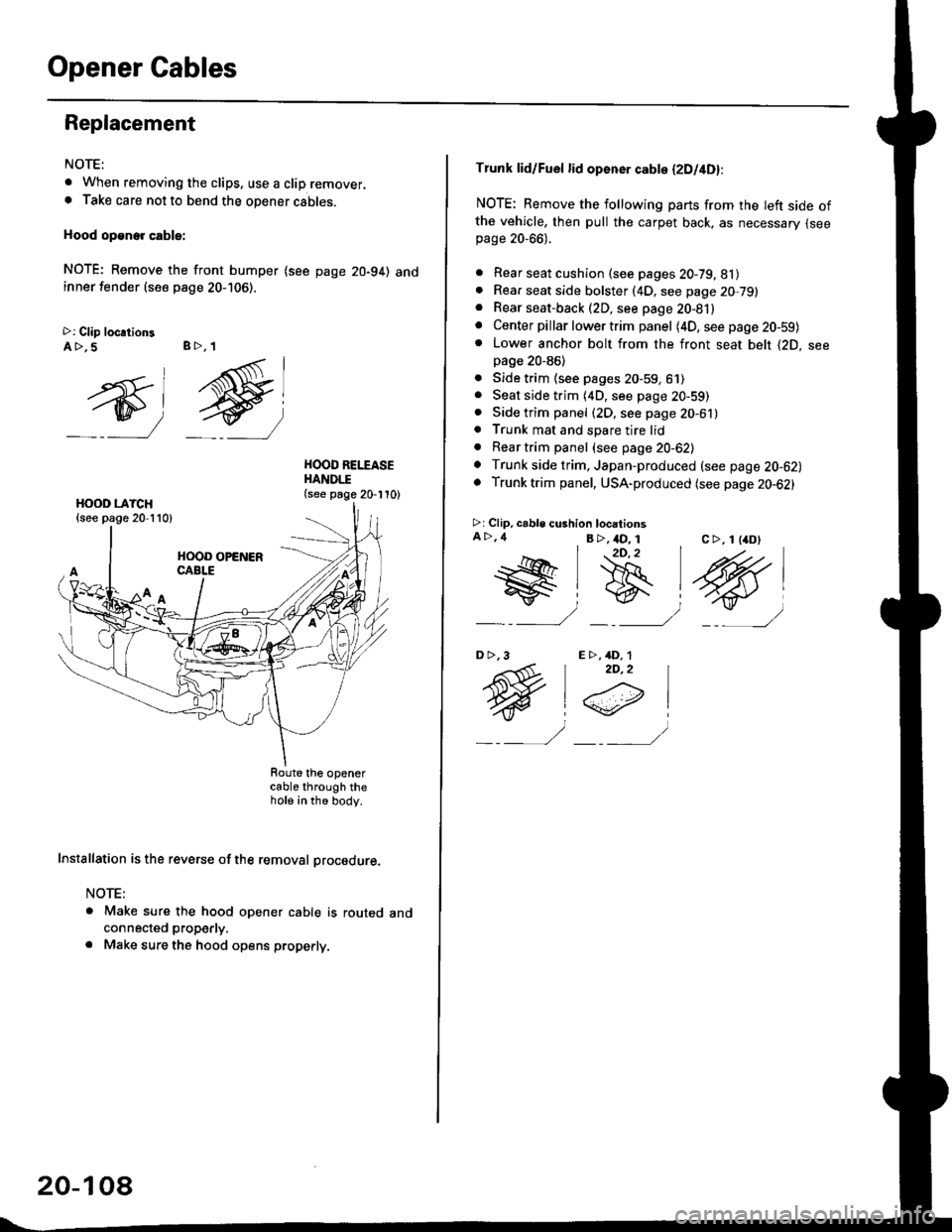
Hood op€ne. cable:
NOTE; Remove the front bumper (see page 20-94) andinner fender (see page 20-106).
>: Clip loc.tionsA >,5 B>, 1
ry)
g
HOOD REI.TASEHANDI.I(see page 20-110)
cable through thehote in th6 body.
Installation is the reverse of the removal procedure.
NOTE:
a Make sure the hood opener cable is routed andconnected properly.
. Make sure the hood opens properly.
20-10a
Tlunk lid/Fuel lid opener cabte (2Dl4D):
NOTE: Remove the following parts from rhe Ieft side ofthe vehicle, then pull the carpet back, as necessary {seepage 20-66).
. Rear seat cushion (see pages 20-79, 81). Rear seat side bolster (4D, see page 20,79). Rear seat-back (2D, see page 20-81). Center pillar lower trim panel (4D, seepage20-59)o Lower anchor bolt from the front seat belt {2D. seepage 20-86)
. Side trim (see pages 20-59, 61). Seat side trim (4D, see page 20-59). Side trim panel (2D, see page 20-61). Trunk mat and spare tire lid. Reartrim panel (see page 20-62). Trunk side trim, Japan-produced (see page 20-62). Trunk trim panel, USA-produced (see page 20-62)
>r Clip, cable cushion locationsA >,4 B >,4D_ 1c >, 1 l4D)2D,2
t@#lB
_ : _/ _-___)
E >,4D, 12D,2
@i
_ _,, -/
D>,3
Page 1340 of 2189
Opener CablesOpener and Latch
Replacement (cont'dl
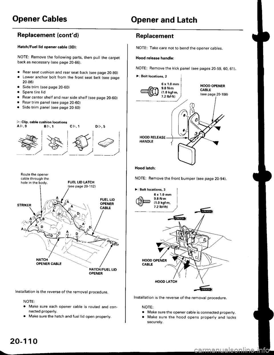
Hatch/Fuel lid opener cable l3Dl:
NOTE: Remove the following parts, then pull the carpetback as necessary (see page 20-66).
. Rear seat cushion and rear seat back (see page 20-80). Lower anchor bolt from the front seat belt (see page
20 86)
. Side trim {see page 20-60). Spare tire lid
. Rear center shelf and rear side shelf {see page 20-60). Rear trim panel (see page 20-60). Side trim panel (see page 20,60)
>: Clip, cable cushion locationsa>.9B>, 1c>, 1D >,5
W#)
FUEL LID LATCH
#,
Route the openercable through thehole in the body.
HATCH/FUEL LIOOPENER
Installation is the reverse of the removal procedure.
NOTE:
. Make sure each opener cable is routed and con-nected properly.
. Make sure the hatch and fuel lid open properly.
page 20-112)
20-110
6x1.0mm j9.8Nm{1.0 kgf.m, i
Replacement
NOTE: Take care not to bend the opener cables.
Hood release handle:
NOTE: Remove the kick panel (see pages 20-59, 60.61).
>: Bolt locations, 2 ]I
HOOO OPENERCABLE(see page 20-108)
Hood latch:
NOTE: Remove the front bumper (see page 20-94).
>: Eolt locations, 3 I6 x '1.0 mm9.8 N.m11.0 kgf.m,
Installation is the reverse of the removal procedure.
NOTE:
. Make sure the opener cable is connected properly.. Make sure the hood opens properly and locks
securely.
Page 1344 of 2189
Windshield Wiper Arms and Linkage
Replacement (cont'dl
USA-produced:
3. Separate the windshield wiper linkage and wind-
shield wiper motor.
Japan/Canada-produced:
NOTE: Scribe a line across the link and windshield
wiper linkage to show the original adjustment.
>: Bolt locations, 3
O 6r1.0mm
EF 8 N.m {0.8 kstm,ig 5.8 tbf.ft) )
NUT10 x 1.25 mml8 N rn (1.8 kgtm,13 tbtftl
>r Bolt locations,3
WIPER LINKAG€
\
20-114
USA-produced:
NOTE: Scribe a line across the link and windshield
wiper motor to show the original adjustment.
>: Bolt locations, 2
R 6J( 1.0 mm
Y 8 N.m to.s kgtm, I
.E- 7Y.nt )
NUT10 x 1.25 mm'18 N.m {1.8 kgf.m.13 tbtft)
WINDSHIELDWIPER MOTOR
4. Installation is the reverse of the removal procedure.
NOTE:
. Make sure the connector is connected properly.
. lf necessary, replace any damaged clips.
. lnstall the windshield wiper arms as described
on page 20-1'17.
. Check the windshield wiper motor operation.. Grease the moving parts.
Page 1345 of 2189
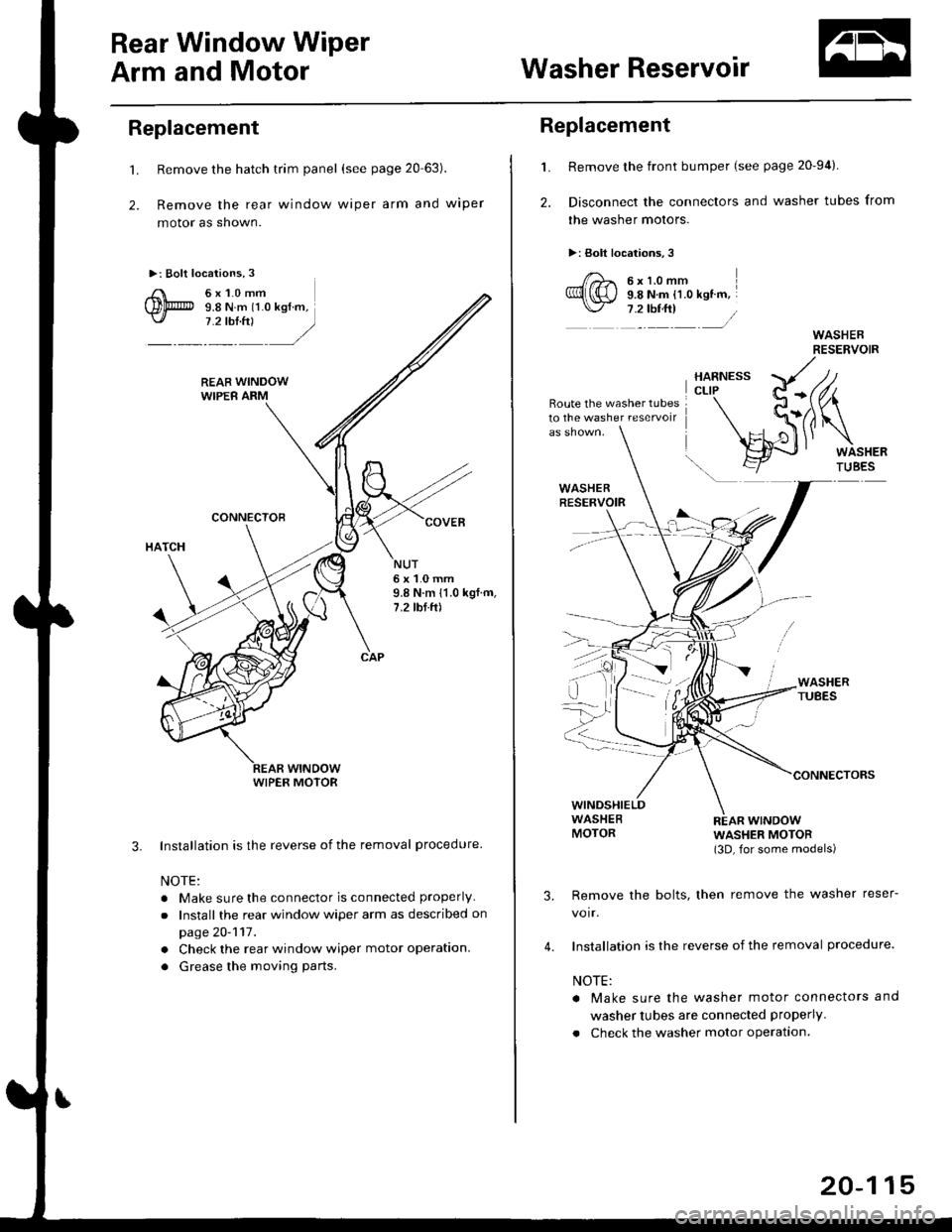
Rear Window Wiper
Arm and MotorWasher Reservoir
Replacement
't.
2.
Remove the hatch trim panel (see page 20 63).
Remove the rear window wiper arm and wiper
motor as shown.
Installation is the reverse of the removal procedure
NOTE:
. Make sure the connector is connected properly
.Install the rear window wiper arm as described on
page 20-117.
. Check the rear window wiper motor operation.
. Grease the moving parts.
3.
NUT6x1.0mm9.8 N.m 11.0 kgf.m,7.2 tbf.ft)
WIPER MOTOR
L
2.
Replacement
Remove the front bumper (see page 20-94).
Disconnect the connectors and washer tubes from
the washer motors.
>: Bolt locations,3
/)^ 6xt.omm
Ql(S) s.e ru.- tt.o ret '".\./ 7 .2 tbf.ft) /
Route the washer tubes10 the washe. reservoir
wtNDowWASHER MOTOR(3D, for some models)
Remove the bolts, then remove the washer reser-
voir.
Installation is the reverse of the removal procedure.
NOTE:
a Make sure the washer motor connectors and
washer tubes are connected properly.
. Check the washer motor operation.
3.
4.
20-115