Page 1809 of 2189

E-
)I
Connect a 12 volt battery to the tool:
. lf the green light on the tool comes on, the aar-
bag igniter circuit is defective and cannot deploy
the airbag. Go to Damaged Airbag Special
Procedure.
. lf the red light on the tool comes on, the airbag is
ready to be deployed.
Push the tool's deployment switch. The airbag
should deploY (deployment is both highly audible
and visible; a loud noise and rapid inflation of the
bag, followed by slow deflation).
. lf the airbags deploy and the green light on the
tool comes on. continue with this procedure.
. l{ an airbag doesn't deploy, yet the green light
comes ON, its igniter is defective. Go to Dam-
aged Airbag Special Procedure.
!!@ During doployment, the airbag sssom'
bly can become hot enough to buln you. Wait thir'
ty minutes aftsr deployment belore touching tho
assembly.
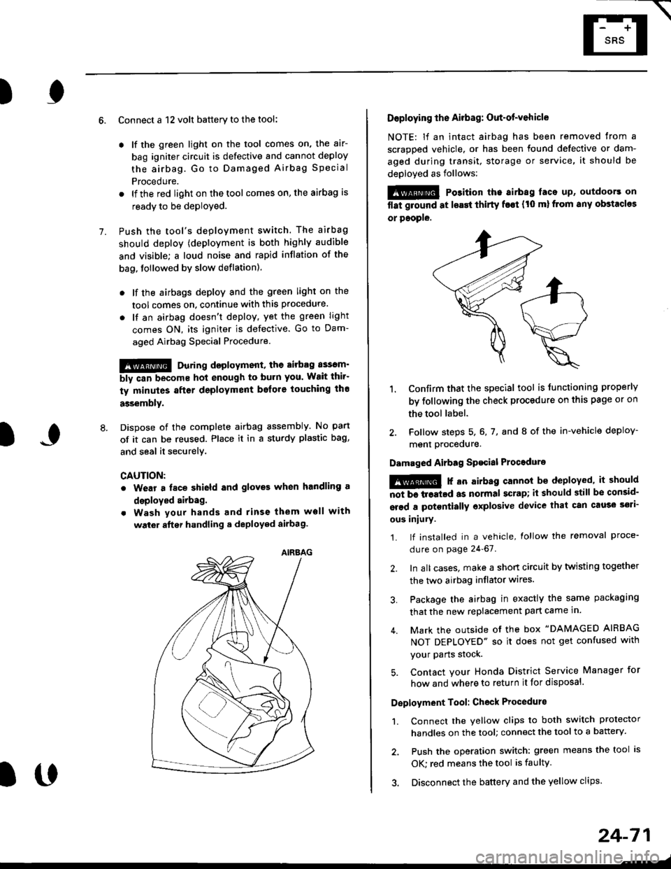
Dispose of the complete airbag assembly. No part
of it can be reused. Place it in a sturdy plastic bag,
and seal it securelY,
CAUTION:
. Wear a fsce shield and gloves when handling a
deployed airbag.
. Wash your hands and rinse them well with
wat6r after handling. deployed airbag.
t('
24-71
7.
AIRAAG
Doploying th6 Airbag: Out-of-vehicle
NOTE: lf an intact airbag has been removed from a
scrapped vehicle. or has been found defective or dam-
aged during transit, storage or service, it should be
deployed as follows:
@ Po3ition the airbag laca up, outdoors on
flat ground at lsast thirty f€€t (t0 ml from any obstacles
or people.
1. Confirm that the special tool is tunctioning properly
by following the check procedure on this page or on
the tool label.
2. Follow steps 5, 6, 7, and I of the in-vehicle deploy-
menl Drocequre.
Damaged Airbag Spacial Procedure
!@ r an airb.g cannot be deployed, it should
iiiTi-treatcd as normal scrap; il should still be consid-
srsd a potontially oxplosive device that can cau3o ssti-
ous iniury.
1. lf installed in a vehicle, lollow the removal proce-
dure on page 24-67.
2. In all cases. make a short circuit by twisting together
the two airbag inflator wires.
3. Package the airbag in exactly the same packaging
that the new replacement part came in.
4. Mark the outside of the box "DAMAGED AIRBAG
NOT DEPLOYED" so it does not get confused with
your Parts stock.
5. Contact your Honda District Service Manager for
how and where to return it for disposal.
Deployment Tool: Check Procedur€
1. Connect the yellow clips to both switch protector
handles on the tool; connect the tool to a battery.
2. Push the operation switch: green means the tool is
OK: red means the tool is faulty
3. Disconnect the battery and the yellow clips.
Page 1812 of 2189

Cable Reel
Replacement (cont'd)
11.
NOTE:
. Before installing the steering wheel, the front
wheels should be aligned straight ahead.. Be sure to install the harness wires so that theyare not pinched or interfering with other parts.. After reassembly. confirm that the wheels arestill turned straight ahead and that the steeringwheel spoke angle is correct (road test). lf minor
spoke angle adjustment is necessary, do so onlyby adjusting the tie-rods, not by removing andrepositioning the steering wheel.
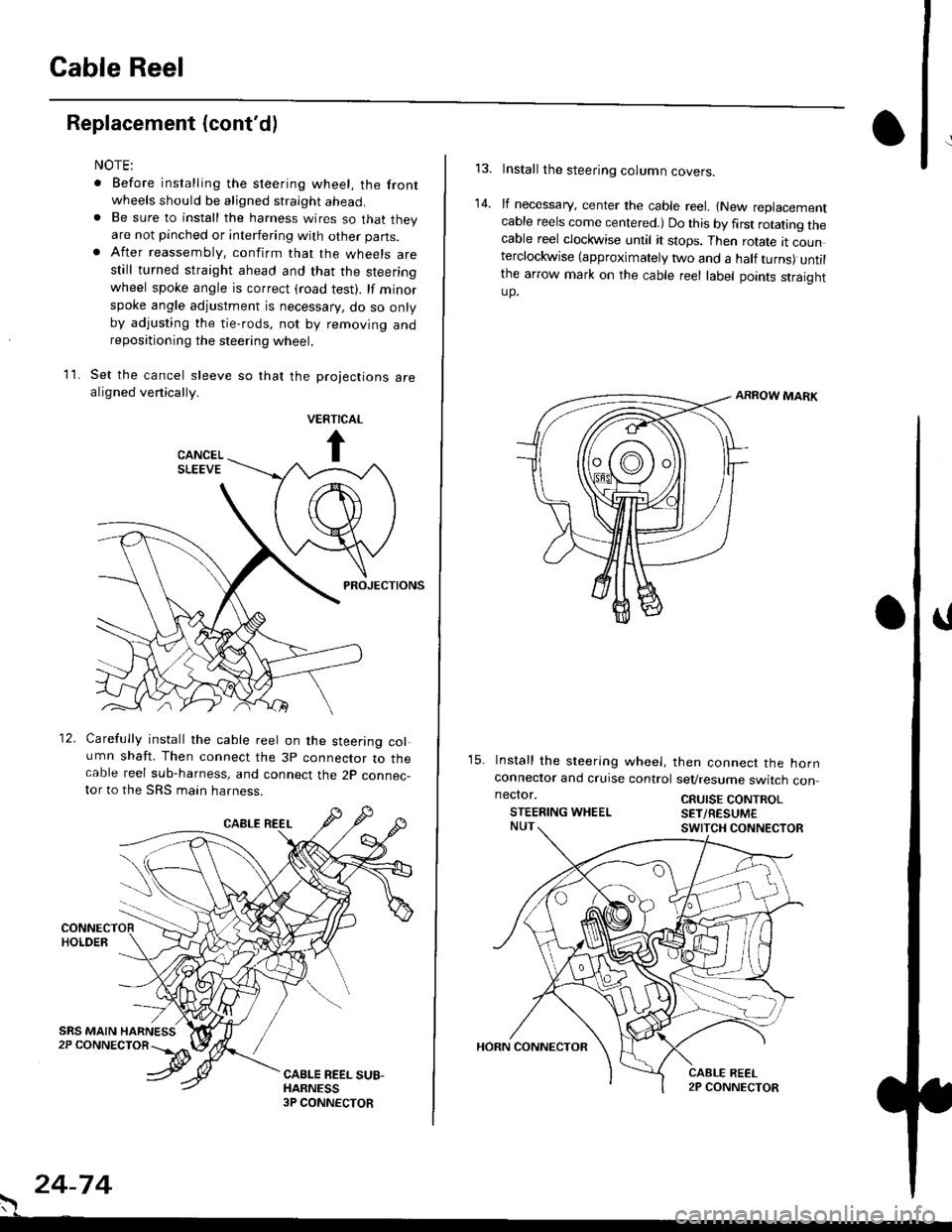
Set the cancel sleeve so that the projections arealigned venically.
PROJECTIONS
12. Carefully install the cable reel on the steering column shaft. Then connect the 3p connector to thecable reel sub-harness, and connect the 2p connec-tor to the SRS main harness.
. 24-74
Install the steering column covers.
lf necessary, center the cable reel. {New replacementcable reels come centered.) Do this by first rotating thecable reel clockwise until it stops. Then rotate tt counterclockwise (approximately two and a half turns) untilthe arrow mark on the cable reel label points straightup.
ARROW MARK
15. lnstall the sleering wheel, then connect the hornconneclor and cruise control sevresume switch con
14.
neclor.
STEERING WHEELCRUISE CONTROLSET/RESUM€
Page 1814 of 2189

SRS Unit
Replacement
CAUTION:
. Betore disconnoqting lny pErt of the SRS wire hal-ness, disconnect th9 airbag conn"ctorlsl.. During installltion or teplacemsnt. do not bump(impact w.cnch, hamm€r stc.l the area noar tho SRSunit.
NOTE:
o Do not damage the SRS unit terminals or connectors.. Do not disassemble the SRS unit; it has no service-able parts,
. Store the SRS unit in a clean, dry a.ea,. Do not use any SRS unit which has be€n subjected towater or shows signs of being dropped or improperlyhandled. such 8s dents, cracks or deformation.
1. Disconnect the bsttery negative cable. then discon-nect the positive cable from the battery, and wait atleast three minutes.
2. Disconnect the airbag connector{s}:
NOTE: When disconnected, the airbag connector isautomatically shorted,
Driver's Side:
. Remove the access panel from the steering wheel.then disconnect the 2P connector between the driv_er's airbag and cable reel (see page 24-11).
Front Passenge/s Side:. Disconnect the 2P connector between the tront oas_senger's airbag and SRS main harness (see page 24-11).
24-76
o\
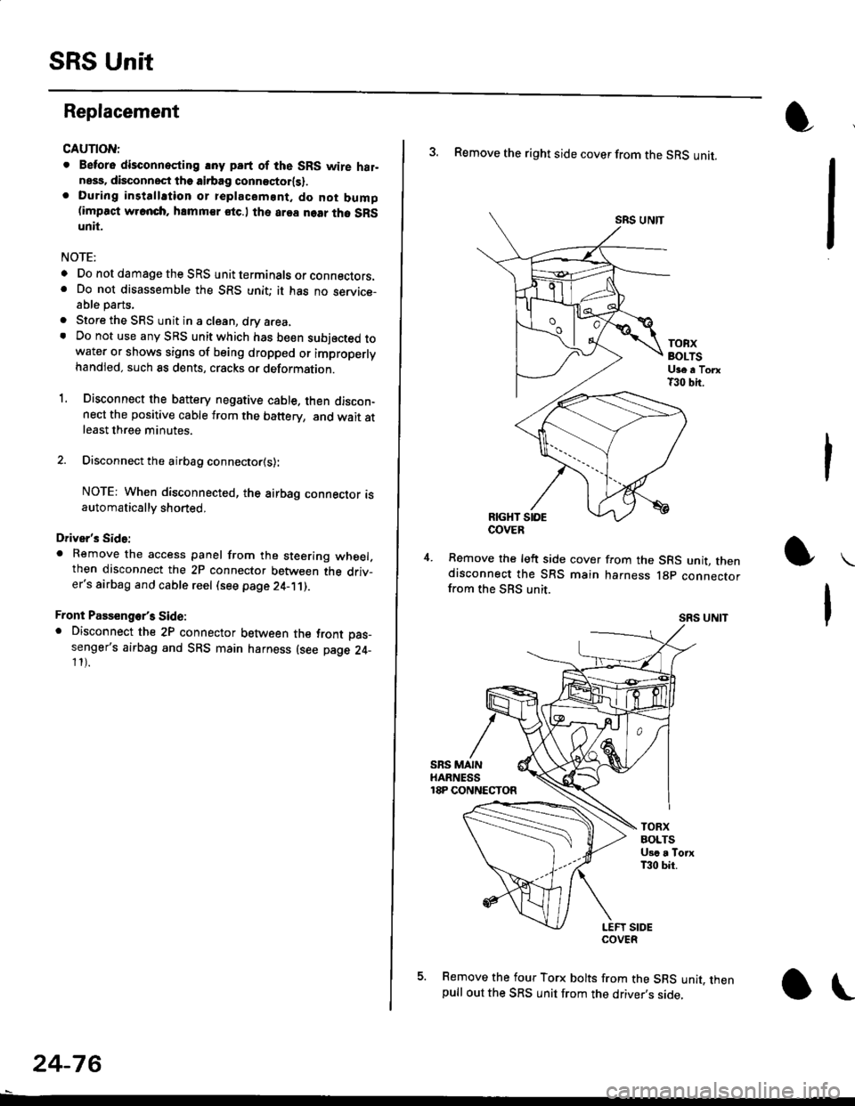
3. Remove the right side cover from the SRS unit.
SRS UNTT
TOBXBOLTSUge a TorxT30 bit.
RIGHT SIOE
Remove the left side cover from the SRS unit, thendisconnect the SRS main harness lgp connectorfrom the SBS unit.
SRS UNIT
5. Remove the four Torx bolts from the SRS unit, thenpull out the SRS unit from the driver,s side,
COVER