1997 HONDA CIVIC Powertrain control module
[x] Cancel search: Powertrain control modulePage 691 of 2189

Electronic Control SYstem
The electronac controt system consrsts of a Powertrain control Module (PcM), sensors, a Iinear solenoid and four solenoid
valves, shifting and lock-up are electronically controlled for comfortable driving under all conditions The PCM is located
below the dashboard, under the front lower panel on the passenger's side
PGM-FIControl Sy3tem
A/T Control SYstom
Shift Control
Lock-uD Control
14-13
Page 717 of 2189

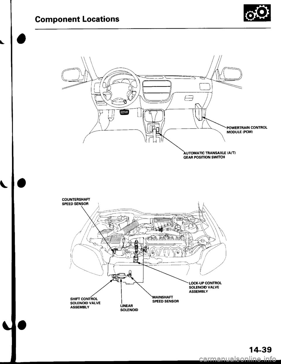
Component Locations
POWERTRAIN CONTROLMODULE (PCM)
TRANSAXLE {A/TI
COUNI€RSHAFTSPEED SENSOR
SOI,TNOID VALVEASSEMBLY
SOLENOID VALVEASSEMBLY
GEAR POSITION SWITCH
SPEED SENSOR
1+39
Page 873 of 2189

Description
The Continuously Variable Transmission (CVT) is an electronically controlled automatic transmission with drive and driv
en Oullevs, and a steel belt. The CVT provides non stage speeds forward and one reverse. The entire unit is positioned in
line with the engine.
Transmission
Around the outside of the flywheel is a ring gear which meshes with the starter pinion when the engine is being staned.
The transmission has four parallel shafts: the input shaft, the drive pulley shaft. the driven pulley shaft, and the secondary
gear shaft. The input shaft is in line with the engine crankshaft. The drive pulley shaft and the driven pulley shaft consist of
movable and fixed face pulleys. Both pulleys are linked by the steel belt.
The input shaft includes the sun gear. The drive pulley shaft includes the forward clutch which mounts the carrier assem-
bly on the forward clutch drum. The carrier assembly includes the pinion gears which mesh with the sun gear and the ring
gear. The ring gear has a hub-mounted reverse brake disc.
The driven pulley shaft includes the start clutch and the secondary drive gear which is integral with the park gear' The sec-
ondary gear shaft is positioned between the secondary drive gear and the final driven gear. The secondary gear shaft
includes the secondary driven gear which serves to change the rotation direction. because the drive pulley shaft and the
driven oullev shaft rotate the same direction. When certain combinations of planetary gears in the transmission are
engaged by the clutches and the reverse brake, power is transmitted from the drive pulley shaft to the driven pulley shaft
to provide E, E, E, and El.
Electronic Control'96 - 98 Models:
The electronic control system consists of the Transmission Control Module (TCM), sensors, three linear solenoids, and a
inhibitor solenoid. Shifting is electronically controlled under all conditions'
The TCM is located below the dashboard, behind the kick panel on the driver's side.'99 - 00 Models:
The electronic control svstem consists of a Powertrain Control Module (PCM), sensors, three linear solenoids and an
inhibitor solenoid. Shifting is electronically controlled under all conditions. A Grade Logic Control System to control shift-
ing in E position while the vehicle is ascending or descending a slope.
The PCM is located below the dashboard, under the kick panel on the passenger's side.
Hydraulic Control
The lower valve body assembly includes the main valve body, the Pressure Low (PL) reguiator valve body, the shift valve
body, the start clutch control valve body, and the secondary valve body. They are positioned on the lower part of the
transmission housing.
The main valve body contains the Pressure High (PH) control valve, the lubrication valve, and the pitot regulator valve.
The secondary valve body contains the PH regulator valve, the clutch reducing valve, the start clutch valve accumulator,
and the shift inhibitor valve. The PL regulator valve body contains the PL regulator valve and the PH-PL control valve
which is ioined to the PH,PL control linear solenoid. The inhibitor solenoid valve is bolted on the PL regulator valve body.
The shift valve body contains the shift valve and the shift control valve. which is joined to the shift control linear solenoid.
The start clutch control valve body contains the start clutch control valve, which is joined to the start clutch control linear
solenoid. The linear solenoids and the inhibitor solenoid are controlled by the TCM or PCM. The manual valve body which
contains the manual valve and the reverse inhibitor valve, is bolted on the intermediate housing.
The ATF pump assembly is located on the transmission housing, and is linked with the input shaft by the sprockets and
the sprocket chain. The pulleys and the clutch receive fluid from their respective feed pipes, and the reverse brake receives
fluid from internal hydraulic circuit.
Shift Control Mechanism
Input from various sensors located throughout the vehicle determines which linear solenoid the TCM or PCM will activate.
Activating the shift control linear solenoid changes the shift control valve pressure, causing the shift valve to move. This
pressurizes the drive pulley pressure to the drive pulley and the driven pulley pressure to the driven pulley and changes
their effective pulley ratio. Activating the start clutch control linear solenoid moves the start clutch control valve. The start
clutch control valve uncovers the port, providing pressure to the start clutch to engage it(cont'd)
14-195
,!
Page 883 of 2189

Electronic Gontrol System ('99 - 00 Modelsl
The electronic controt system conststs of a Powertrain control Module (PCM). sensors, three linear solenoids and an
inhibitor solenoid. shifting is electronically controlled under all conditions A Grade Logic control system to control shift-
ing in E position while the vehicle is ascending or descending a slope'
fn"pCVirlocatedbelowthedashboard,underthekickpanelonthepassenger'sside'
The pCM controls the transmassion to reduce engine speed and retain the engine's cooling efficiency when the vehicle is
driven with full throftle acceleration
lf the vehicle is continuously driven at lull throttle acceleration, the PCM regulates the pulley hydraulic pressure to
increase the pulley ratio which. as the result, reduces the engine speed and retains the designed cooling efficiency After
the vehicle has been driven at a lower engine speed for a while, the PCM increases the pulley ratio to the original ratio'
i"i ".nl",rr starting in the E position, the PcM cuts off the ,Vc clutch (if the A/c is on) and increases the engine speed to
900 rpm when the transmission is shifted to the E position'
The start clutch functions to make smooth starting possible. To let the start clutch function properly, the PcM regulates
the start clutch hydraulic pressure based on the engine's negative pressure memorized in the E position'
FCM
s*o.d.ry G..t Sh.h
(cont'd)
14-205
Page 1840 of 2189

Ground-to-Components I ndex
f.,lONOTE: All ground wires are BLK unless otherwise noted.
GroundPageComponents or Circuit Grounded
Battery (BLKYEL)
Steering pump bracket
t+-rg ITransmission housing
l
G101
(-1)
G101
(-2)
14-2
and
14-3
ano
14-1
Powertrain or engine control module (PG1 and pG2 are BLK: LG1 and LG2 are
BRN/BLK), EGR control solenoid valve (CW, EGR valve and lift sensor (Dt6yS enginewith M,/T), Engine coolant temperature switch, pGM-Fl main relay, power steeringpressure switch (USA), Primary HO2S (D16Y5 engine with l\/,/T), Vehicle speed sensor,VTEC pressure switch (D16Y5/D16Y8 engines), CKF sensor (BRN/BLK), Transmission
control module (CYf) (Pc1 is BLK: LG1 is BRN/BLK)
Shielding betvveen the PCM or ECM and these components (all have BRN/BLK wires):
CKF sensor, TDC/CKP/CYP sensor. Primary and secondary heated oxygen sensors.
Knock sensor (CWDl6YB engine), Mainshaft speed sensor (AiT except CVT),
I Countershaft speed sensor (A/T except CVf)
Shielding between the TCM and these components (CVT) (all have BRN/BLK wires):
Drive pulley speed sensor, Driven pulley speed sensor, Secondary gear shaft
speed sensor
Powertrain or engine control module (PG1 and pG2 are BLK; LG1 and LGz are
BRN/BLK), EGR control solenoid valve (D16Y5 engine), EGR valve (Dt685), Engine
coolant temperature switch, Fuel pressure regulator shut-off solenoid valve (D1685),
PGM-FI main relay, Power steering pressure switch (USA), Vehicle speed sensor, VTECpressure switch (All except D16Y7 engine), CKF sensor (A
except 81642) (BRN/BLK)
Shielding between the PCM or ECM and these components (all have BRN/BLK wires):
CKF sensor, TDC/CKP/CYP sensor, Primary and secondary heated oxygen sensors,
Knock sensor (All except D16Y7 engine), i/ainshaft speed sensor (Arf except CW),
Countershaft speed sensor (A,/T except CVf), Drive pulley speed sensor (CW), Drivenpulley speed sensor (CVT), Secondary gear shaft speed sensor (CVf)
I Badiator fan motor, Right front parking/turn signat tight, Right headtight
G20214-4I Cruise control actuator, Left front parking/turn signal lights, Left headlight, Rear window
I washer motor, Windshield washer motor, Washer fluid level switch (,99-'00 Canada)
G401| +-o
and
14-7
Accessory power socket, Brake fluid level switch, Clutch interlock switch (M/T), Clutchswitch (lillT with cruise/D16Y5 engine with MfD, Combination wiper switch (Z wires),
Cruise control main switch, Cruise control unit, Dash lights brightness controller, Data
link connector, Daytime running lights control unit (Canada), Gauge assembly, Horn('96-'97 models), Integrated control unit, Interlock control unit (ArI), Keyless door lock
control unit ('99-'00 models with keyless), Moonroof close and open relays, Moonroof
switch, Park pin switch (A/r), Power window relay, Rear window defogger relay, Rear
window defogger switch ('96-'98 models), Steering lock, Stereo radio tuner (,96-,98
USA: LX, EX, and HX), Turn signal/hazard relay, Windshield wiper motor.....plus
everything grounded through G402
6-6
Page 1853 of 2189

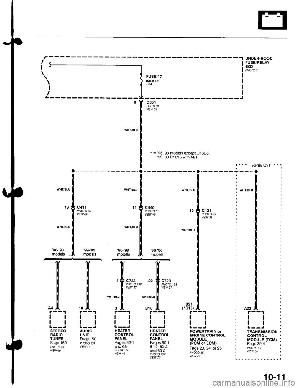
* = '96-98 models except D1685,'99100 D16Y5 with lVl/T
UNDER-HOODFUSE/RELAYBOX
'98CW - -.
, r--1
:ll:,tt:
: r--J ;, TRANSMISSION ,. CONTROL' MODULE OCM) :' Page 3g-4 ;I PHOIO 121I vlEW 69
I
I
\FUS€ 47aAcx uP
c351
WHT/BLIJ
WHT/BLU
WHT/BLU
18c4'l t
vlEw 60
WHT/ALU
WHT/ALU
11c440
WHT/BLU
10
' WHT/BLU
, 423
c131
vtEw 59
WHT/BITJ
'96-'98
models
I
tl
tl
STEREORADIOTUNERPage 150
'99-'m
modelsmodeB
'99-'�00
models
c723c723
vtEw 57
wHr/atu
810B�21cc10)
tl
ll
HEATERCONTROLPANELPages 60-1,61-2,62-2,and 63-2
vtEw 76
tl
tl
POWERTRAIN oTENGINE CONTROLMODULE(PCM or ECM)
Page 23, 24, ot 25
AUDIOUNITPage 150
tl
HEATERCONTROLPANELPages 62-1and 63'1
10-1 1
Page 1857 of 2189

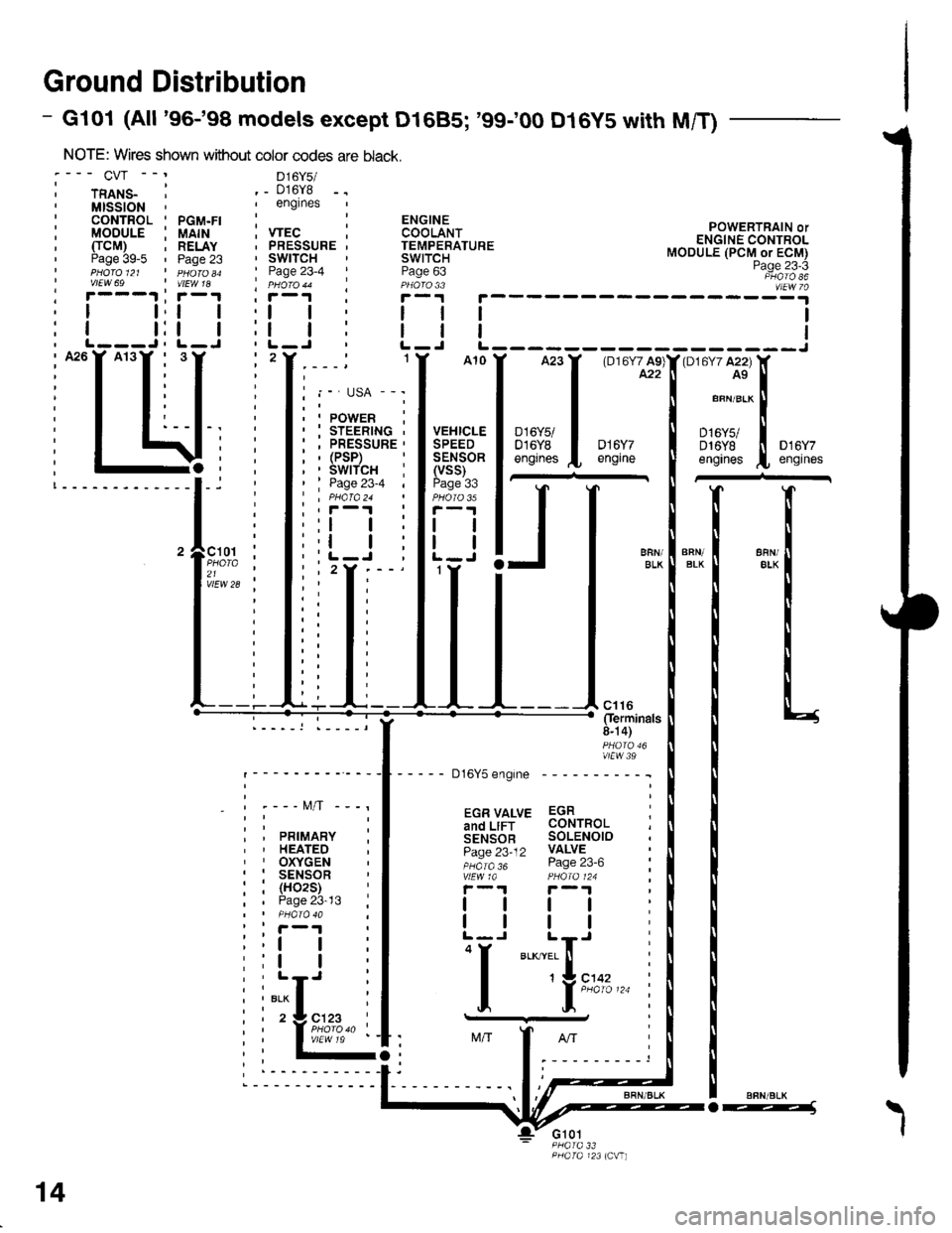
Ground Distribution
- Gl01 (All '96-'98 models except D1685; '99100 D16y5 with M/T)
NOTE: Wires shown without color codes
:--- CVr --' D16y5/
i rnlts_ ' ._ 016y8,MISSION',englnes
: CONTROL ' PGM.FI :: MODULE i UAIH ; VTEC, TTCM) ; RELAY . PRESSURE' Paae 39-5 ' Paoe 23 ' SWITCHI pHdro et ' n 6roao ' Page 23-4I vtEw 69 | vtEw 1a ' pHoro 44' r---.t ' r-1 I i-r
POWERTRAIN orENGINE CONTROLMODULE (PCM or ECM)Page 23-3PHATO 86vlEw 7a; r---1 ;r-1 , r, I t,t | ,l
: I t:t | :l, L---J, L-J ' L-, A26Y A13Y , 3,2
i T T: I I
I I, I t,,-I T T: T i
: I t:--I-. :
i I \li:; -4, ;!-------------l-i '
'lF;% :21 ,vlEw 28 ;
_ - t\4/T -
PRIMARYHEATEDOXYGENSENSOR(H02S)Page 23-13
ll
tl
"i[",..
14
o---1\
I
Page 1859 of 2189

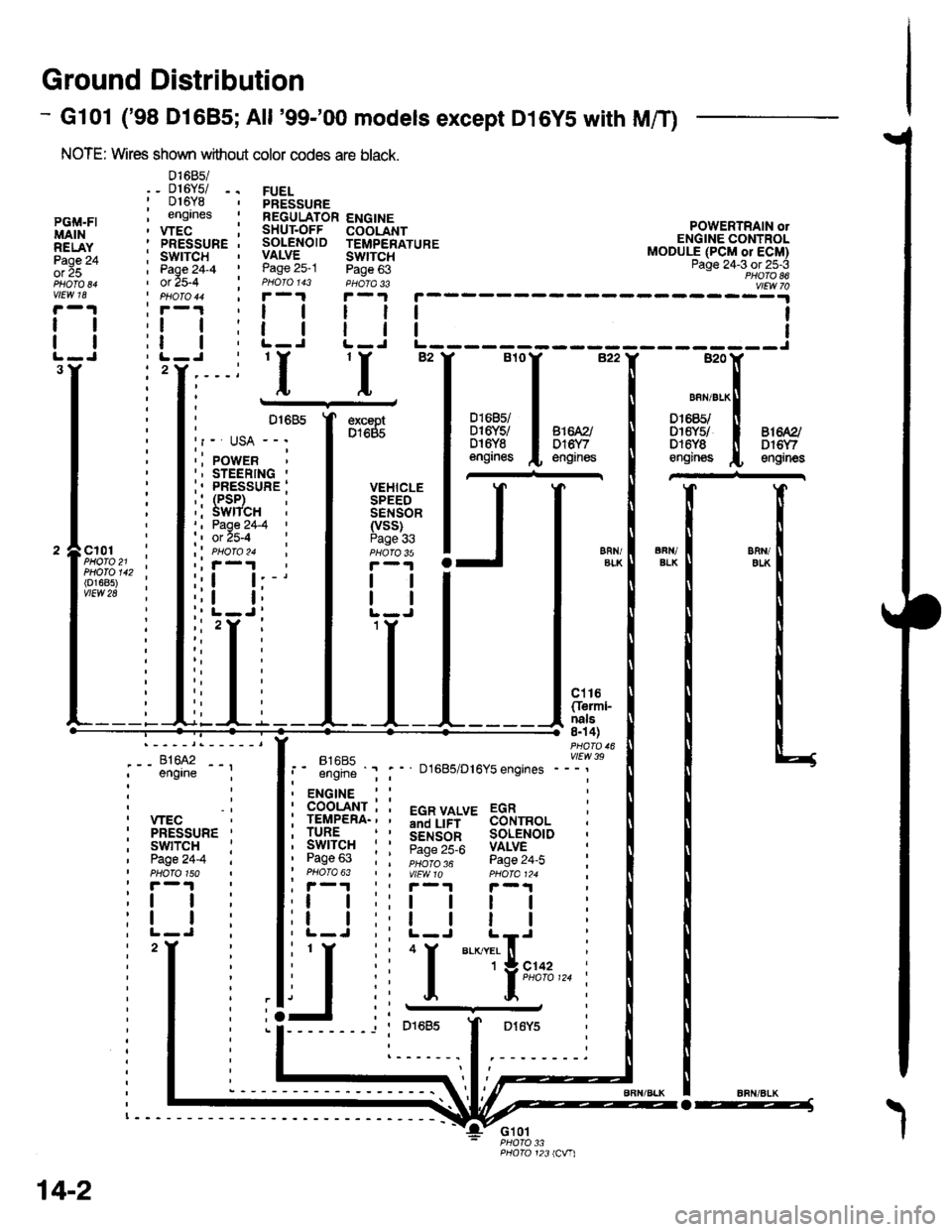
Ground Distribution
- Gl01 ('98 Dl685;All '99-'00 models except D16YS with M/T)
NOTE: Wires shown without color codes are black.
01685/_ D16Y5/ -.016Y8engrnes
.__-;,#'-_,--', engrne ;
, wEc: PRESSURE '
, swtTcH :I Page24-4 iI PHOTO 150: r -'l
:t | :
:l | :,L-J.
FUELPRESSUREREGULATOR ENGINESHUT.OFF COOLANTSOLENOID TEMPERATUREVALVE SWTTCHPage 25-1 Page 63PHOIO 143 PHOTA 33r-1F-.|
llll
lltlL-J L-J
POWERTRAIN olENGINE CONTROLMODULE (PCM or ECM)Page 24-3 ot 25-3PHOTO 86
----:y4
tl
tl
PGi,|.FIMAINRELAYPage 24ol 25
vlEw 18
tl
tl
3Y'I'I
excaptD1685
VEHICLESPEEDSENSOR(vss)Page 336FN/ELKERll/EIKcl01PHOTO 21PHOTO 142(o1685)vtEw 28
ct16Cferml-nals8n 4)
FltaFt( vttw 39t- .''iiti ' " D1685/D16Y5 engrnes ---'
t2
. ENGINE : :
i 933'?il-; i 5"T,Yf,*' 33i,"o, i
i lgfft" i I S.ir1".l^ soL€NorD :' Pase 63 : : ;;;;; - pase 24.i :' PHOTO 63 | | VtEWlO pHOIa124 ;, r-1 | , F-.t r-.r
:l | ;:l | ! | :;t | :,t | | | ;
j,f
ii T.__.,|,,,,,.
j
--
----- --l i otoas I Dr6y5 :
:------.1.--------.
14-2
o-----J