Page 1921 of 2189
i - '99100 016Y7/D16Y8 with A"/T -
Cruiseconrolsgnal
i8s) i
iil
POWERTRAINCONTROLMODULE(PcM)
* = '96-'98: All models'99100: D16Y5 with M/T, 01685
-----i-----.lcRU|sE
| ; Cruise control ' I CONTROL
signaloutput ' |oNirI PHATO 55
I oisengage input vehicle speed input ' vtEw 13
.--------;---- ---J
See Vehicle
Sensor rySS)
See GfoundDigtribution,page 14-5.
I
J
"{
,--r-s=-.
CLUTCHswtTcHOpen withclutch pedaloepresseo.
A/T GEARPOSITIONswtTcH
L- ----
ALU,ryVHT
3x
ct30Cferminals11.13)PHATO E3vlEw 52See GrolndDlslribution,page 14-6.
IY
ll
L__l#: G401
lI:::1" I
I output I
VEHICLESPEEDSENSOR(vss)
O-a
34-3
Page 1924 of 2189
@@
i t FusE 13
LJ::-i1":--.i
---1 UNDET
| | ryql* !5ts?'n| ) iL"' li'r:,o,
rT ILJ---------J
--1 UNDER.DASH T ---1 UNDER-HOOD
i l$5ffif{61 !F'[]:':'* itte*- l"l;?::*'
L-g----- ---Y---J3 r-----
---------;r
".* I veuar-r< |, t_____ _1ft9#;,,
"* | ;-{ 8pfitli*| ".'"'* |
n"""
l----l .rr^ Page 14 1
-Fliirn"r"a-rq) 1' i====f:a&l?f''inarsra-rzr
"*l w;?"* ! .._ _ .l .- " .l *.*- I #it;;;--
-
lara-i-�-�'' i I @DP':,-rt
r=- 9,lo,l' o.,., I *ol- --t PowER-(rGPr) rrcP2lI TRAIN
Countersl€lt so€€d
sbneor
lJt
"":I ""1I BRNJELX
"r, | "'0 I
!-
-CIG; - - - - - - - -*-r- - 1 PowERTRAIN
t sensor t"r'ii. | .c.gl,rfgL
I gourd ground I F;-r,r;*L------- J iuoro ea
Mainshaftspoedsensorinpd
Power input
#lvrrwzo
CONTROLMODULE(PCM)PHOTO 86
(NM) (PG1) {P62) {LG0 (LG2)
":[
;{ ]1
::l -X ;;
rfl lfi* *T'r+*
| | |
:T'-jru,,L#, il
3.[iF;" H ;,$5*" I
n:'r:T'"'uo
l #lt':.See GrourdDisttlbution,page 14.
(cont'd)
BRN/BLKBFN/BLK
39-1
Page 1925 of 2189
![HONDA CIVIC 1997 6.G Workshop Manual A/T Controls (All 96-98 Models except CW and GX) (conto;
t(
E!@----.!powERTRAtN FT-------.tuNDER_DASHI rp Fcr ; coiir-noi-"
I I ruse zs i Fu5iiaer-av
I l""E,T* n"ey i"l,"l !i[!!i* ! ] rtr" 96; HONDA CIVIC 1997 6.G Workshop Manual A/T Controls (All 96-98 Models except CW and GX) (conto;
t(
E!@----.!powERTRAtN FT-------.tuNDER_DASHI rp Fcr ; coiir-noi-"
I I ruse zs i Fu5iiaer-av
I l""E,T* n"ey i"l,"l !i[!!i* ! ] rtr" 96;](/manual-img/13/6068/w960_6068-1924.png)
A/T Controls (All '96-'98 Models except CW and GX) (cont'o;
t(
E!@----.!powERTRAtN FT-------.tuNDER_DASHI rp Fcr ; coiir-noi-" '
I I ruse zs i Fu5iiaer-av
I l""'E,T* n"ey i"l,"l' !i[!!i* ! ] rtr" 96;"g; !F,9"T"*
L-Eg-----st ____.tsg_.i;ffi',"."" L.E-Es:Jtr._.iDro lf Di Y
---:4-rv'tw/0 Lll---=:--J
';[
"l
"."-11[ ,ixlt"tt',"i'r,e1,-,--^^.**!-'
|
-;'i
..".. ""f-ru'i:':,&***r
[q",",".,.
""""il '"'"."1 "'""'-l
ffiffi:!*r** |
:""=n-G""*'.n;-
o"n"''"
'[-
"[
"-TI
"..#%$.i"]
-[T,"."""1
F*=t--^,1 ffi
ll I
cari'erxf
i?:_::I=::IF_=I-_:l
.i*_-____,-l ! !lf--1-*",",,""n
! ;a""" I
'l
^' I T:l
*'il,[
I I cari,erxf i;:::f::::F_-_-_-:f_-_-_;7
.L------,-l _ RorrLE I i i i-::"rrri_:_;] ( in--TlIr:9;lIl,EM a I i \
l-l$.#N ii 9- lt',t.';-iil:,811'*",!
iia_**,( | l\
I
't"
! iLI-------L*J___-/ )
"",."',.1
I N
'-*'r---::::::--^Fr-----
!!
L____.____+___{e,E- tr*?,i. i nl,,rl#t
(
(ferminals
D't 1
: (sG2, lD4 rNDrI si,"#,
| 9round
!:;1", i ".-l I
L__lo=--H: G401
c136
vtEw 2a
,il'f,*u,*.
1
I
I
POWERTRAINCONTROLMODULE (PCM)
*l = '96 016Y8 enginei All Coupes'97 D16Y7 enoine: CaliforniaCoupe, Calitoinia Sedan LX'97 D16Y8 enorne: AllCouoes.Calrtornia Sed-an'98 model: All
*2 = '96 016Y8 enoine: AllexceotCoupes'97 D16Y7 enqrne: AllexceolCalrfornia Coupe and Califdf-nia Sedan LX'97 D16Y8 enqtne. A
exceotCoupes and ealrfornra Sed;n
a
39-2
Page 1933 of 2189
A/T Controls ('98 GX and All '99-'00 Models except CW) (cont'd)
(
\la
t
\
\
\
I
t
I
\
I
I
t
I
t
\
POWERTRAIN
! t*,*" ffi,v i"lll i[?Hl,1P.
L _gA _ _ _ _ _g'L _ _ _ _ yy _ j ii?i%'"
*:ll--
",."
-1
"-TX
YEL
.[-Qhuit"I
miftu.*
.Li--,1
""":l
iii
F=lm+';I ii,r-;.'_
I tiJ.l______
i 1",,'"'."."-*{
TfleolTla's8.14)
I
"""'"'.
f
""r.:
I
",,1 ;il
UNDER-DASHFUSE/RELAYBOXiT-*-.'-;---l
LJ5Effi$iJ
lL[9*?:{. csoT
See PowerDistribution,page 10-6.
===a oerm|nars 17-20)
lJ'�lll"-+
See Dash and Console Lights
l*'r
L__l+: G40t
See GroundDistribution,c€lge 14-7.
J:I
I
c410
vlEW 35
c136
vtEw 20
r--,"";---- -----^-_=--r powERTRAtN
I s"""iy n'i'^- lcoNTRoL
i ;a; iiii"rto, i MoDULE (PcM)
L------- ----:Slgrol- -j ur-iic,
SeePGM-FI
39-10
Page 1934 of 2189
POWERTRAINCONTROLMODULE(PCM)
t1fo 85'59
36 GX) rfo 142'20
= lrale-Female)rminals are also)versed on GX
-I POWET
I Parrv I c-oNrF
i l"=9"' l?v.9rse gll[gR'Y'
L-g-g-- Jg:l----i'11---iltP. ---:y!iii:;?""
::: I ::I ::I :1I :]:I
.-*1,*,. ",il**'*, ";l-i$;'r,,,. ,"*,f r,h,h.r::lnfft
:l*r*;'"1
l#+u"1
g_'" 9?,o;1"",.r n"n I
u't"" caucEAssE
nro I PI
SeeA/T GearPositionlndicator
*,, I
-l
See A,/TGearPositionlndicator
,nrt I
-
See !y'TC*arhsitionIndicator
A/T GoarPositionIndicaior
c410
V|EW35 WHT
o
13
GBN12GFNAVHI.! AiT GEARPOSTTIONSWITCH
See Cruise Control
39-11
Page 1957 of 2189

- How the Circuit Works
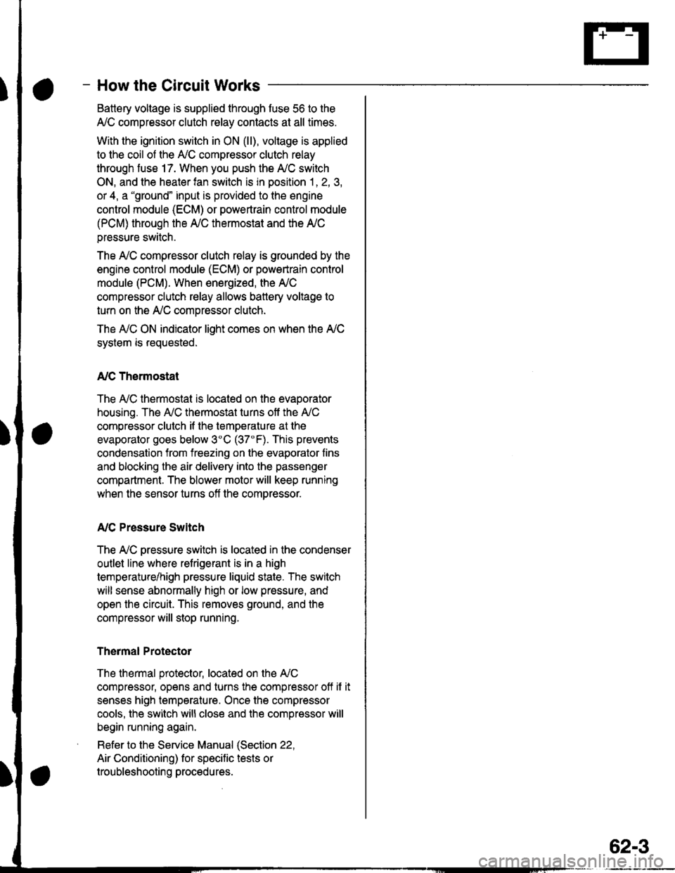
Battery voltage is supplied through tuse 56 to the
A,/C compressor clutch r€lay contacts at all times.
With the ignition switch in ON (ll), vollage is applied
to the coil of the A,/C compressor clutch relay
through fuse 17. When you push the A,/C switch
ON, and the heater fan switch is in position | , 2, 3,
or 4, a "ground" input is provided to the engine
control module (ECM) or powertrain control module
(PCM) through the l'lC thermostat and the l'lC
pressure switch.
The A,/C compressor clutch relay is grounded by the
engine control module (ECM) or powertrain control
module (PCM). When energized, the A'lC
compressor clutch relay allows battery voltage to
turn on the A,/C comDressor clutch.
The A,/C ON indicator light comes on when the A,/C
system is requested.
A,/C Thermostat
The A'lC thermostat is located on the evaoorator
housing. The A,/C thermostat turns off the A,/C
compressor clutch if the temperature at the
evaporator goes below 3'C (37'F). This prevents
condensation from freezing on the evaporator fins
and blocking the air delivery into the passenger
compartment. The blower motor will keep running
when the sensor turns off the comDressor.
A,/C Pressure Switch
The fuC oressure switch is located in the condenser
outlet line where refrigerant is in a high
temperature/high pressure liquid state. The switch
will sense abnormally high or low pressure, and
open the circuit. This removes ground, and the
compressor will stop running.
Thermal Protectot
The thermal protector, located on the A,/C
compressor, opens and turns the compressor off if it
senses high temperature. Once the compressor
cools, the switch will close and the compressor will
begin running again.
Refer to the Service Manual (Section 22,
Air Conditioning) for specific tests or
troubleshooting procedures.
62-3
Page 1958 of 2189
Fans
- AllModels\,1 |
splicedtogetherinstead of inthe junctionconnector onDl6Y5 models
c211PHOTO 11
FANRELAYPrtofo 10
Se€ I'i CCompre€sorCont ols
1
ALKAED
a
c352
f BLKaEou Y 9,;%,.cFN I vIEw 5e
;
"'
T
";::-:.."-!
Y:. ---::Y h!ii'in"," :
I : ""'I 'is.2o) :
I i,o''ur,ff;, l;l:'l?'* i
I r- - -, |JBEI :
I ; I control | ;
I :L--J :I ' PoWERTRAIN ordu. ' ENGINE CONTROL '' MODULE
: (PCMoTECM) :I PHAfO 86I wEw 7allqA ----.ENGINECOOLANTTEMPERATUREswtrcH BLLPHO|O 33 ?
Ses GrolndDiskibution,oaqe 14.
,I
H
:I
i:
"'*
1_l
c7531
BLU/BLK
ALK2
BLK
RADIATORFANMOTORI
BLK
BLK1
ELK
c753
CONDENSERFANMOTOR
a
* czsr
page 14.
II
FJ'Glot
c211
Gro!nd
T
Se€ GroundOstribution,Pago 14.4"t1 - '96.f98: All models'99-'00: 016Y5 with M/I 01685"2 = '99-'00: Allmodels exceptD16Y5 with M/T and 01685
cof{oENs€R
* czor33123lCVIl
63
Page 1961 of 2189

- How the Circuit Works
Radiator Fan
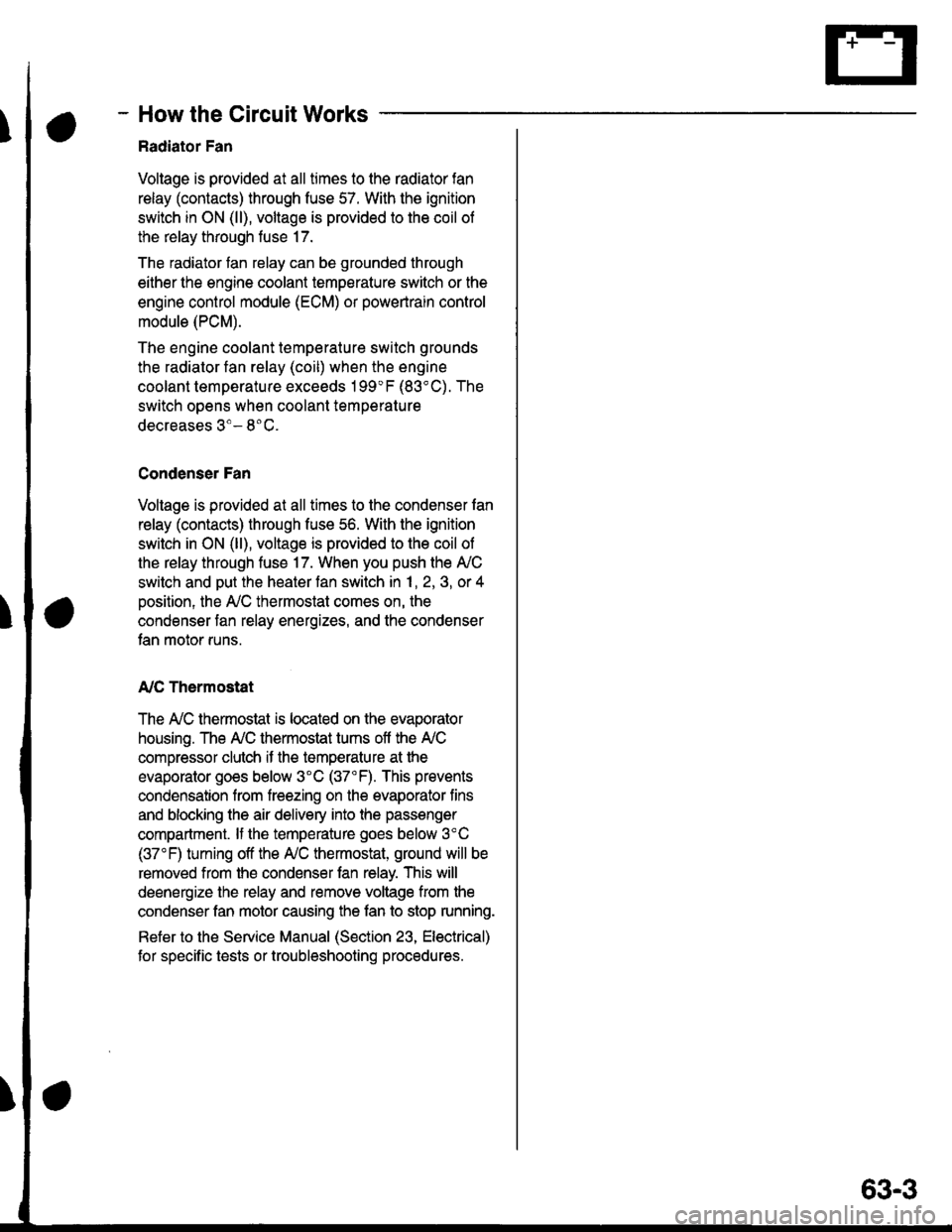
Voltage is provided at all times to the radiator fan
relay (contacts) through fuse 57. With the ignition
swilch in ON (ll), voltage is provided to the coil of
the relay through luse 17.
The radiator tan relay can be grounded through
either the engine coolant temperature switch or the
engine control module (ECM) or powertrain control
module (PCM).
The engine coolant temperature switch grounds
the radiator fan relay (coil) when the engine
coolant temperature exceeds 199'F (83'C). The
switch opens when coolanl temperature
decreases 3'- 8'C.
Condenser Fan
Voltage is provided at all times to the condenser fan
relay (contacts) through fuse 56. With the ignition
switch in ON (ll), voltage is provided to the coil of
the relay through fuse 17. When you push the A'lC
switch and put the heater fan switch in 1, 2,3, o( 4
position, the ly'C thermostat comes on, the
condenser fan relay energizes, and the condenser
fan motor runs.
A,/C Thermostat
The A,/C thermostat is located on the evaporator
housing. The A,/C thermostat tums off the A/C
compressor clutch if the temperature at the
evaporator goes below 3'C (37'F). This prevents
condensation from freezing on the evaporator fins
and blocking the air delivery into the passenger
compartment. lf the temperature goes below 3'C
(37"F) tuming off the Ay'C thermostat, ground will be
removed from the condenser fan relay. This will
deenergize the relay and remove voltage from the
condenser fan motor causing the fan to stop running.
Reter to the Service Manual (Section 23, Eleckical)
for specific tests or troubleshooting procedures.
63-3