Page 1027 of 2189

22. Install the shift cable end on the control lever, and
install the shift cable on the shift cable bracket'
CAUTION: Take care not to bend the shift cable'
23. lnstall the clip in the direction shown.
LOCKNUT
SHIFI CABLE 29 N m {3.0 kg{ m, 22lblftl
SHIFT CABLEERACKET
WASHERIPLASTIC)
CONTROL LEVER
24, Connect the solenoid harness connector. the drive
pulley speed sensor connector. and the ground
cable terminals.
6x1.0mm12 N.m {1.2 kgf.m.8,7 rbtft)
GROUND CABLETERMINAL 6x1.0mm
GROUNDTERMINAL
12 N.m {1.2 kgf'm,8.7lbtfrl
DRIVE PULLEYSPEED SENSORCONNECTOR
SOLENOID HARNESS
CONNECTOR
25. Connect the starter motor cable on the starter motor.
and install the cable holder.
NOTE: When installing the staner motor cable. make
sure that the crimped side of the ring terminal is
facing out (see section 23).
STARTEB
BMOUNTING NUT
9 N.m (0.9 kgf m,7 lbf ft)
26. Install all removed connectors and clamps'
27. Install the distributor.
28. Install the intake air duct and air cleaner housing
29.
assemDly.
Refill the transmission with the recommended
Genuine Honda CVT Fluid (see page 14-2991
CAUTION: While filling the CvT Fluid, bs surs not io
allow dust and other fotoign particles to entor into
the transmission.
Connect the battery positive (+) terminal first, then
the negative (-l terminal to the battery'
Check the ignition timing (see section 23).
Start the engine. Set the parking brake, and shift the
transmission through all gears three times Check
shift cable adjustment (see page 14-355).
Check the front wheel alignment (see section 18)
Let the engine reach operating temperature (the
radiator fan comes on) with the transmission in lXl
or E position, then turn it off and check fluid level'
Perform the start clutch calibration procedure on
page 14-293.
Road test as described on pages 14-296 and 14-297
30.
31.
34.
36.
STARTER MOTOR
14-351
Page 1031 of 2189
t
Adjustment
!@ Make sure lifts, jacks and safety stands are
placed properly (see section 1).
l. Remove the front console (see section 20).
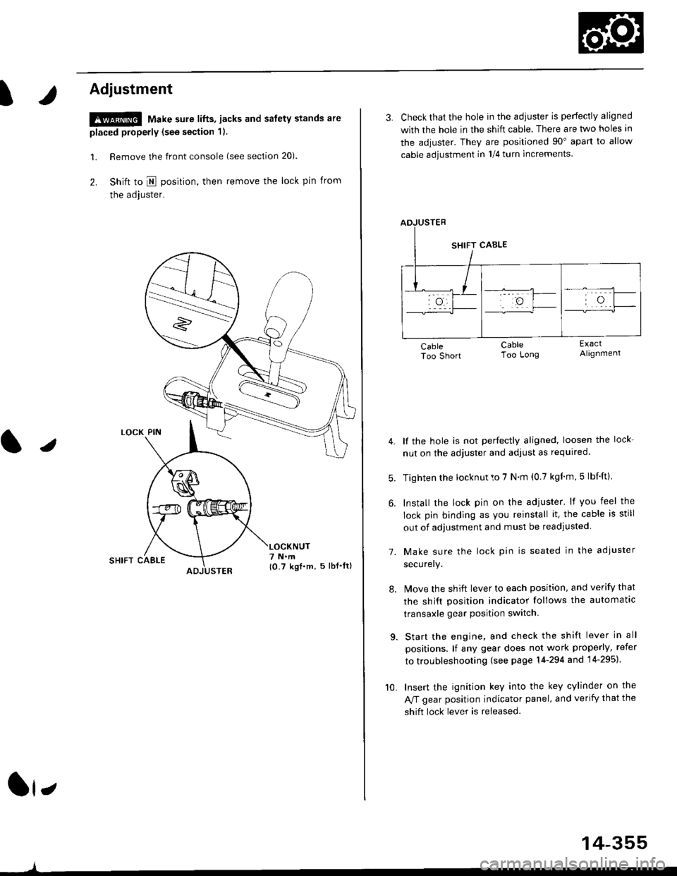
2. Shift to I posirion, then remove the lock pin from
the adjuster.
SHIFT CAELE
l,
,l
{0.7 kgf.m, 5lbf'ltl
3. Check that the hole in the adiuster is perfectly aligned
with the hole in the shift cable. There are two holes in
the adjuster. They are positioned 90" apart to allow
cable adjustment in 1/4 turn increments.
lf the hole is not perfectly aligned, loosen the lock-
nut on the adjuster and adjust as required.
Tighten rhe locknut to 7 N.m (0.7 kgim,5 lbf'ft).
Install the lock pin on the adjuster' lf you feel the
lock pin binding as you reinstall it. the cable is still
out of adjustment and must be readjusted
Make sure the lock pin is seated in the adiuster
securery.
lMove the shift lever to each position, and verify that
the shift position indicator follows the automatlc
transaxle gear position switch.
Start the engine, and check the shift lever in all
positions. lf any gear does not work properly, refer
to troubleshooting (see page 14-294 and 14-295).
Insert the ignition key into the key cylinder on the
Aff gear position indicator panel, and verify that the
shift lock lever is released.
7.
10.
14-355
Page 1073 of 2189
)
Steering Pump
Construction
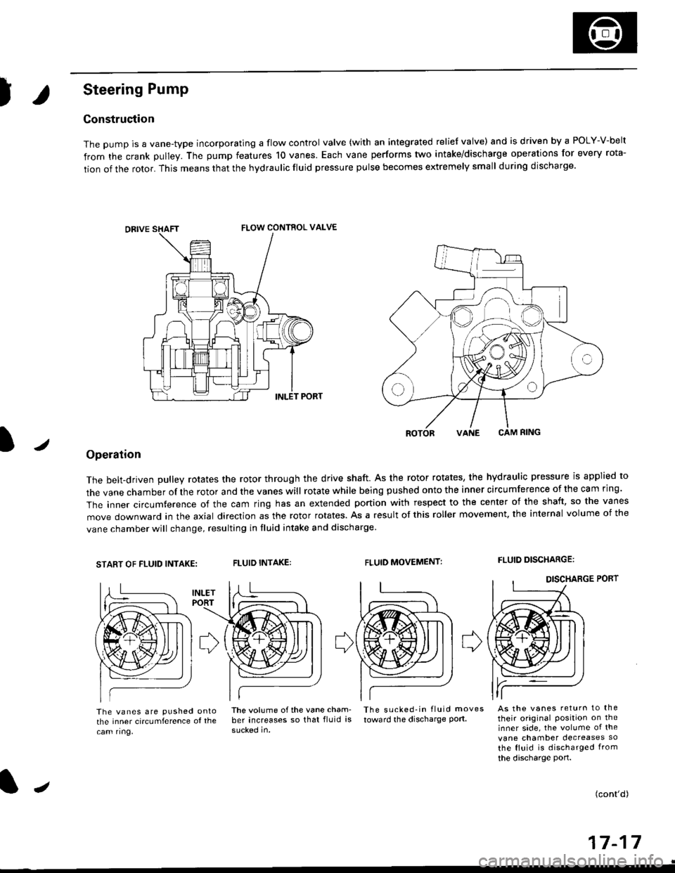
The pump is a vane-type incorporating a flow control valve (with an integrated relief valve) and is driven by a POLY-V-belt
from the crank pulley. The pump features 10 vanes. Each vane performs two intake/discharge operations for every rota-
tion of the rotor. This means that the hydraulic fluid pressure pulse becomes extremely small during discharge.
/
ROTORVANE CAM RING
Operation
The belt-driven pulley rotates the rotor through the drive shaft. As the rotor rotates, the hydraulic pressure is applied to
the vane chamber of rhe rotor and the vanes will rotate while being pushed onto the inner circumference of the cam ring.
The inner circumference of the cam ring has an extended portion with respect to the center of the shaft, so the vanes
move downward in the axial direction as the rotor rotates. As a result of this roller movement. the internal volume of the
vane chamber will change, resulting in fluid intake and discharge
START OF FLUID INTAKE:FLUID INTAKE:FLUID MOVEMENT:FLUID DISCHARGE:
The vanes are pushed ontothe inner circumference ol the
cam ring,
lhe volume ofthe vane cham- The sucked-in fluid moves
ber increases so that fluid is toward the discharge port.
sucked in.
As the vanes return to the
their original Position on theinner side, the volume of the
vane chamber decreases so
the fluid is discharged from
the discharge port.
(cont'd)
a-t 4-I I- | t
FLOW CONTROL VALVE
J
Page 1074 of 2189
System Description
Steering Pump (cont'dl
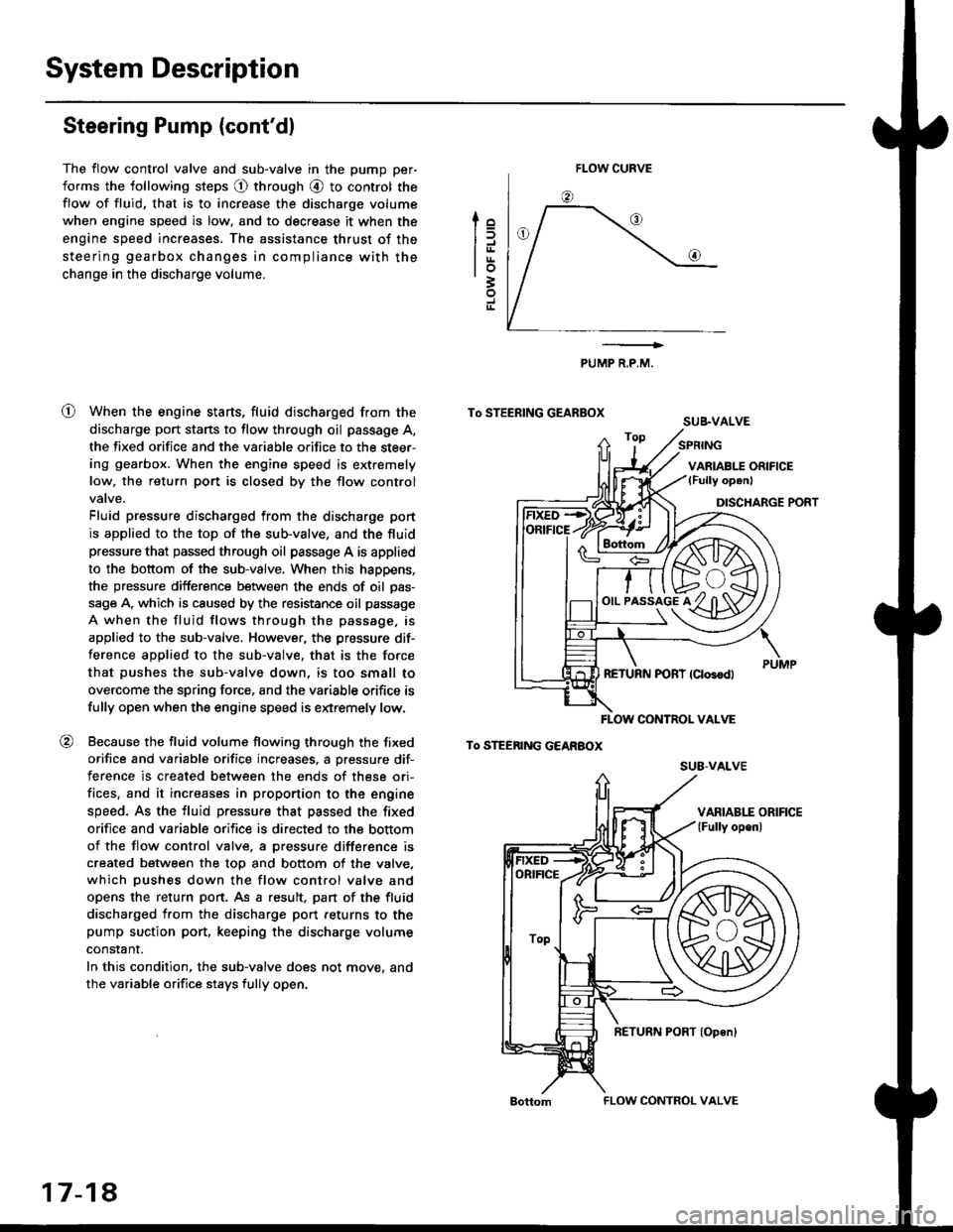
The flow control valve and sub-valve in the pump per-
forms the following steps @ through @ to control the
flow of fluid, that is to increase the discharge volume
when engine speed is low, and to decrease it when the
engine speed increases. The assistance thrust of the
steering gearbox changes in compliance with the
change in the discharge volume.
When the engine starts, fluid discharged from the
discharge port starts to flow through oil passage A,
the fixed orifice and the variable orifice to the steer-
ing gearbox. When the engine speed is extremely
low, the return port is closed by the flow control
Fluid pressure discharged from the discharge port
is applied to the top of the sub-valve, and the fluid
pressure that passed through oil passage A is applied
to the bottom of the sub-valve. When this happens,
the pressure difference between the ends of oil pas-
sage A, which is caused by the resistance oil passage
A when the fluid flows through the passage. is
applied to the sub-valve, However, the pressure dif-
ference applied to the sub-valve. that is the force
that pushes the sub-valve down, is too small to
overcome the spring force, and the variable orifice is
fully open when the engine speed is extremely low.
Because the fluid volume flowing through the fixed
orifice and variable orifice increases, a pressure dif-
terence is created between the ends of these ori-
fices, and it increases in proportion to the engine
speed. As the fluid pressure that passed the fixed
orifice and variable orifice is directed to the bottom
of the flow control valve. a pressure difference is
created between the top and bottom of the valve,
which pushes down the flow control valve and
opens the return port. As a result, pan of the fluid
discharged from the discharge port feturns to the
pump suction port, keeping the discharge volume
constant.
In this condition, the sub-valve does not move. and
the variable orifice stays fully open.
lo
trrtrrlo3
J
o
PUMP R.P.M.
To STEERING GEARBOXSUB.VALVE
To STEEnING GEARBOX
FLOW CURVE
!rs+/f/ffih\
o,,-i^"l^tKzYt)91y ul3Yl
FLOW CONTNOL VALVE
su8-vALvE
ORIFICE
ToP
17-18
FLOW CONTROL VALVE
Page 1079 of 2189
I
AbnormalDeformed
Faulty cylinder lines
Adiustment OK
Faulty valve body unit
Normal
IICompair the steering to another alike
vehicle.
/
Check the force required to turn
the wheel (see Page 17 30i
Start the engine and measure the
force required to turn the wheel
to the right and left. Difference of
the lorce required to turn the
wheel to the right and to the Ieft
should be 2.9 N 10 3 kgf, 0.7 lbf)
or below.
Check for bent rack shaft
Check rack guide adiustment (see
page 17-33).
(cont'd)
17 -23
1,,
Page 1082 of 2189
Troubleshooting
Noise and Vibration
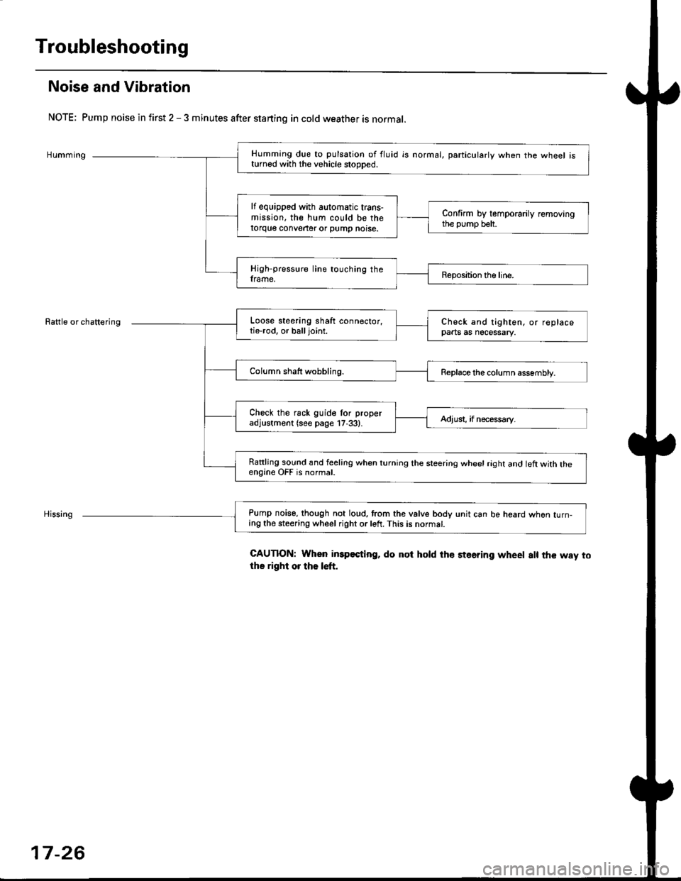
NOTE; Pump noise in first 2 - 3 minutes after starting in cold weather is normal.
Humming
Rattle or chattering
Humming due to pulsation of fluid is normal, particularlv when the wheel isturned with the vehicle stooDed.
lf equipped with automatic trans-mission, the hum could be thetorque conveater or pump noise.
Confirm by temporarily removingthe pump belt.
High-pressure line touching theframe.Reposition the line.
Loose steering shaft connector,tie-rod. or balljoint.Check and tighten, or replacepaats as necessary.
Column shaft wobbling.Replace the column assembly.
Check the rack guide tor properadjustment (see page 17,33).Adiusi, if necess€ry.
Rattling sound and feeling when turning the steering wheel raght and left with theengine OFF is normal.
Pump noise, though not loud. trom the valve body unit can be heard whon turn-ing the steering wheel right or left. This is normat.
CAUTION: When imp€sting, do not hold the steering wheet a[ the way tothe right or the left.
17-26
Page 1083 of 2189
)
Pump noaseGrating noisefrom pump
Pump gear nois€
Check the tluid level.
lf low, fill the reservoir to the
proper level, and check lor leaks.
Tighten or replace as nocessary.
Cavitation caused bY air bubbles
in the fluid.
Check lor a crushed suction hose
or a loose hose clamp allowing
air into the suction side of the
sy$em.Tighton or roplace as necossary.
NOTE: Pump noise uP to 2 - 3
minutes alter starting in cold
weather is normalCompare pumP noise at operating
temperature to simular vehicle.
lf pump nois€ is abnormallY loud,
remove and inspect the PUmP for
w6ar and damage (see Page 17-
41).
lz/
Rattle or chattgring
17-27
Tighten or replace the Pulley.lf shatt is loose, rePlace thepump.
tr
Page 1086 of 2189
Inspection and Adjustment
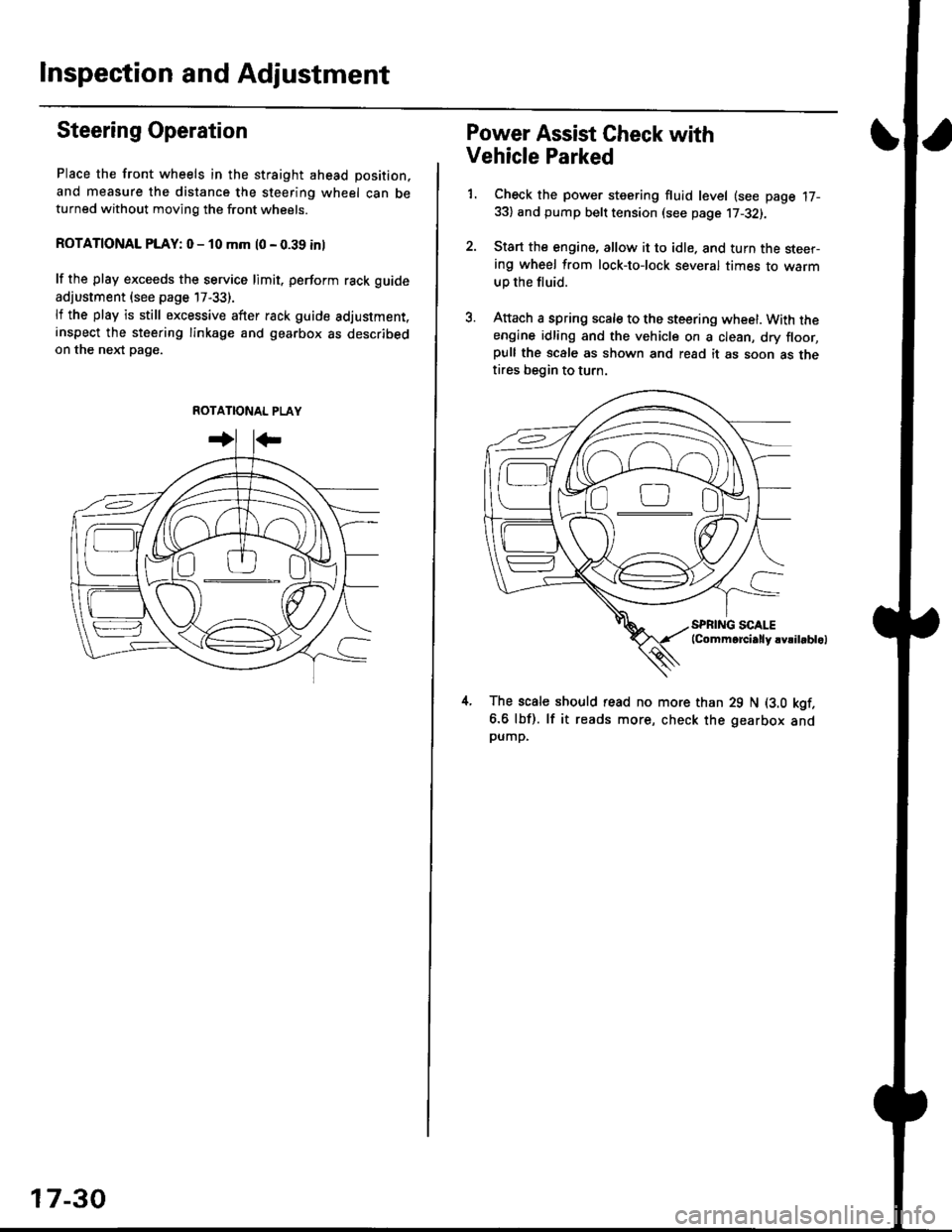
Steering Operation
Place the front wheels in the straight ahead position,
and measure the distance the steering wheel can beturned without moving the front wheels.
ROTATIONAL PLAY: 0 - 10 mm l0 - 0.39 inl
lf the play exceeds the service limit. perform rack guide
adjustment (see page 17-33).
lf the play is still excessive after rack guide adjustment.inspect the steering linkage and gearbox as describedon the nel(t pag€.
ROTATIONAL PLAY
17-30
Power Assist Gheck with
Vehicle Parked
1. Check the power steering fluid level (see page 17-33) and pump belt tension (see page 17-32).
2. Start the engine, allow it to idle. and turn the steer-ing wheel from lock-tolock several times to warm
up the fluid.
3. Attach a spring scale to the steering wheel. With theengine idling and the vehicle on a clean, dry floor,pull the scale as shown and read it as soon as thetires begin to turn.
The scale should read no more than 29 N (3.0 kgf.
6.6 lbf). lf it reads more, check the gearbox andpump,
D0