1997 HONDA CIVIC Start
[x] Cancel search: StartPage 1088 of 2189
Inspection and Adjustment
Pump Belt
NOTE: When using a new belt, first adjust the deflection
or tension to the values for the new belt, then readjust
the deflection or tension to the values for the used beltafter running engine for five minutes.
Inspection
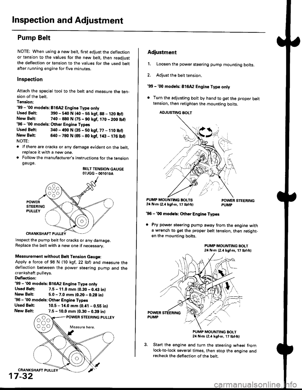
Attach the special tool to the belt and measure the ten-sion of the belt.
Tension:'99 -'00 mod€ls: B1642 Engin. Type onlyUsed Bsh: 390 - 540 N lao - 55 kgt.88 - 120 tbf)New Belt:740 - 880 N {75 - 90 kgf, 170 - 200 tbt}'96 - '00 models: Other Engine Types
Used Beh: 340 - 490 N (35 - 50 kgf, 77 - ilO tbflNew Belt:640 - 780 N 165 - 80 ksf, 1& - 176 tbf)NOTE:
. lf there are cracks or any damage evident on the belt,reDlace it with a new one.. Follow the manufacturer's instructions for the tensiongauge.
BELT TENSION GAUGE07JGG _ 001010A
Inspect the pump belt for cracks or any damage.Replace the belt with a new one if necessary.
Measuremont without Beh Tension Gauga:
Apply a force of 98 N (10 kgt,22 lbfl and measure thedeflection between the power steering pump and thecrankshaft pulleys.
Dsflectior:'99 -'00 model3: 816A2 Engine Typ€ ontyUsed Beh: 7.5 - 11.0 mm t0.30 - 0.43 inlNew Beh:5.0 - 7.0 mm (0.20 - 0.28 in)'96 - '00 models: Othor Engine Typos
Used Behi 10.5 - 14.0 mm (0.ial - 0.59 inlNow Beh:7.5 - 10.0 mm (0.30 - 0.39 inl
POWER STEERING PULUY
CRANKSHAFT PULLEY
17-32
Adiustment
1. Loosen the power steering pump mounting bolts.
2. Adjust the belt tension.
'99 - '00 mod€ls: 816A2 Engin€ Typo only
. Turn the adjusting bolt by hand to get the proper belttension, then retighten the mounting bolts,
ADJUSNNG BOLT
PUMP MOUNNNG BOLTS24 N.m (2.4 kgf'm, 17 tbtftlPOWER STEERINGPUMP
'96 -'00 modek: Othcr Engins Typos
. Pry power steering pump away from the engine witha wrench to get the proper belt tension, then retight-en the mounting bolts.
PUMP MOUNTING BOLT24 N.m (2,4 kgf.m, 17 lbl.ftl
PUMP MOUNTING BOLT24 N.m {2.a kgt m, 17 tbtftl
Start the engine and turn the steering wheel fromlock-to-lock several times, then stop the engine andrecheck the deflection of the belt,
Page 1089 of 2189
IRack Guide Adjustment
NOTE: Perform rack guide adjustment with the wheels
in the straight ahead Position.
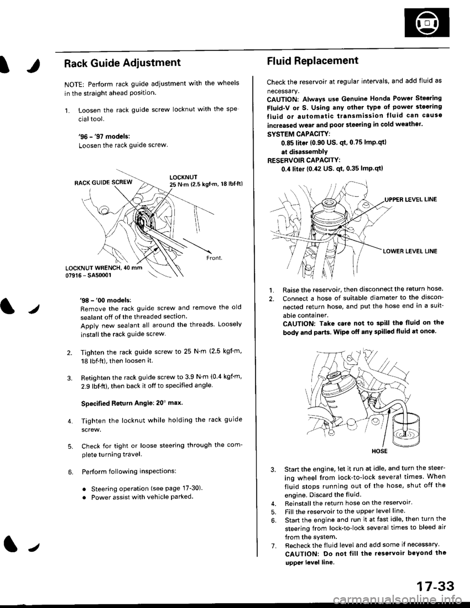
1. Loosen the rack guide screw locknut with the
cialtool.
'96 - '97 models:
Loosen the rack guide screw
'98 - '00 models:
Remove the rack guide screw and remove the old
sealant off of the threaded section.
Apply new sealant all around the threads. Loosely
installthe rack guide screw
Tighten the rack guide screw to 25 N'm (2.5 kgf'm.
18 lbf.ft), then loosen it.
Retighten the rack guide screw to 3 9 N'm (0.4 kgim,
2.9 lbf.ft), then back it off to specified angle.
Specified Return Angle: 20" max.
Tighten the locknut while holding the rack guide
screw.
Check for tight or loose steering through the com-
plete turning travel.
Perform following insPections:
. Steering operation (see page 17-30).
. Power assist with vehicle parked.
4.
LOCKNUT WRENCH, 40 mm
lr
17-33
Fluid Replacement
Check the reservoir at regular intervals, and add fluid as
necessary.
CAUTION: Always us€ Genuine Honda Power Stearing
Fluid-V or S. Using any other type of power sto€ring
tluid or automatic transmission lluid can cause
increased wear and poor steering in cold weathor.
SYSTEM CAPACITY:
0.85 liter 10.90 US' qt,0.75 lmp'qt)
at disassembly
RESERVOIR CAPACITY:
0.4 liter (0.42 US. qt, 0.35 lmP.qt)
LEVEL LINE
LOWER LEVEL LINE
1. Raise the reservoir, then disconnect the return nose.
2. Connect a hose of suitable diameter to the discon-
nected return hose, and put the hose end in a suit-
able container.
CAUTION: Take care not to spill tho fluid on the
body and parts. Wipe off any spill€d fluid at oncs'
3. Start the engine, let it run at idle, and turn the steer-
ing wheel from lock-to-lock several times When
fluid stops running out of the hose, shut off the
engine, Discard the fluid.
4. Reinstall the return hose on the reservoir'
5. Fill the reservoir to the upper level line.
6. Start the engine and run it at fast idle, then turn the
steering trom lock-to-lock several times to bleed air
trom the system.
7. Recheck the fluid level and add some it necessary.
CAUTION: Do not fill the reservoir beYond the
upper l€vel line.
HOSE
Page 1090 of 2189
lnspection and Adjustment
Pump Pressure Check
Check the fluid pressure as follows to determine
whether the trouble is in the pump or gearbox.
NOTE: First check the power steering fluid level andpump belt tension.
CAUTION: Disconnect the high pr$sure hos€ with care
so as not lo spill the power sieering tluid on tha frame
and other parts.
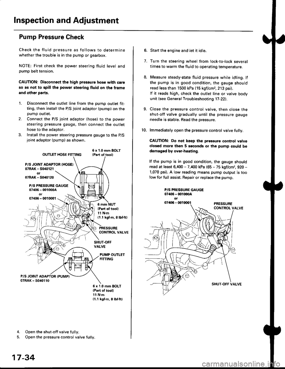
1. Disconnect the outlet line from the Dumo outlet fit-
ting, then installthe P/S joint adaptor (pump) on the
Dumo outlet.
2. Connect the P/S joint adaptor (hose) to the power
steering pressure gauge, then connect the outlet
hose to the adaptor.
3. Install the power steering pressure gauge to the P/Sjoint adaptor (pump) as shown.
ourlEr HosE FnrNo ,t"ll lrilu"ott
P/S JOINT ADAPTOB IHOSEI07RAK - S0i10l2rol07RAK- 50{{)120
P/S PRESSURE GAUGE07406 - 001000Aor07406 - 0010001
4. Open the shut-off valve fully.
5. Open the pressure control valve fully.
17-34
(Pa.t of tooll11 N.m11.1 kgt m, 8 lbf.ftl
PRESSURECONTROL VALVE
SHUT.OFFVALVE
PUMP OUTLETFITTING
6 x 1.0 mm BOLTlPart of tool)11 N.m11.1 kgf m, 8 lbtftl
7.
Start the engine and let it idle.
Turn the steering wheel from lock-to-lock several
times to warm the fluid to operating temperature.
Measure steady-state fluid pressure while idling. If
the pump is in good condition, the gauge should
read less than 1500 kPa (15 kgf/cmr, 213 psi).
lf it reads high, check the outlet line or valve body
unit (see General Troubleshooting 17-22).
Close the pressure control valve, then close the
shut-off valve gradually until the pressure gauge
needle is stable. Read the oressure.
lmmediately open the pressure control valve fully.
GAUTION: Do not keep lhe prossure control valve
clos€d more then 5 soconds or the pump could be
damagod by over-heating.
lf the pump is in good condition, the gauge should
read at least 6,400 - 7,400 kPa (65 - 75 kgflcm,, 920 -
1,070 psi). A low reading means pump output is too
low for full assist. Repair or replace the pump,
9.
P/S PBESSURE GAUGE07{16 -@1@OA
oi
SI{UT.OFF VALVE
Page 1123 of 2189
)
1?
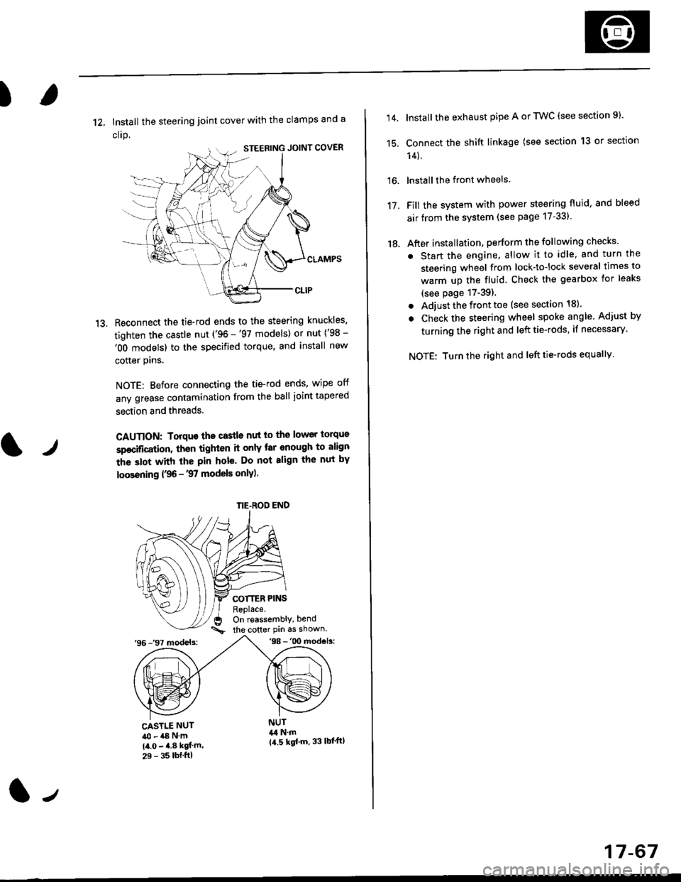
12, Install the steering joint cover with the clamps and a
clrp.
Reconnect the tie-rod ends to the steering knuckles,
tighten the castle nut ('96 -'97 models) or nut ('98 -
'OO models) to the specified torque, and install new
cotter plns.
NOTE: Before connecting the tie-rod ends, wipe off
any grease contamination from the ball joint tapered
section and threads.
CAUTION: Torquo the castle nut to the lower torque
sp€cification, then tighten it only tar enough to align
the slot with the pin hole. Do not align the nut by
loosening {,96 -'97 models only).
COTTER PINSReplace.On reassembly, bend
the cotter Pin 6s shown.'96 -'97 models:'98 -'00 mod€ls:
tr
CASTLE NUT40 - a8 N'm(4.0 - 4.8 kgf'm,29 - 35 lbf.ftl
NUT&l N.m{a.5 kgf'm, 33 lbl'ftl
NE-ROD END
(l-,
17-67
14.
15.
16.
17.
18.
Install the exhaust pipe A or TWC (see section 9).
Connect the shift linkage (see section 13 or section
14).
lnstall the front wheels
Fill the system with power steering fluid, and bleed
air from the system (see page 17-331
After installation, perform the following checks
. Start the engine, allow it to idle, and turn the
steering wheel from lock-tolock several times to
warm up the fluid. Check the gearbox for leaks
(see page 17-39).
. Adjust the front toe (see section 18).
. Check the steering wheel spoke angle. Adjust by
turning the right and left tie-rods, if necessary.
NOTE: Turn the right and left tie-rods equallv
Page 1160 of 2189
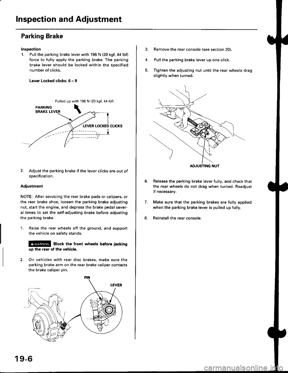
Inspection and Adjustment
Parking Brake
Inspection
1. Pull the parking brake lever with 196 N {20 kgf. 44 lbf)
force to fully apply the parking brake. The parking
brake lever should be locked within the sDecified
number of clicks.
Lever Locked clicks: 6 - I
Pulled up96 N 120 kgf,44lbf)
2. Adjust the parking brake if the lever clicks are out of
specification.
Adiusiment
NOTE: After servicing the rear brake pads or calipers, or
the rear brake shoe, loosen the parking brake adjusting
nut, start the engine, and depress the brake pedal sever-
al times to set the self-adjusting brake before adjusting
the parking brake.
1. Raise the rear wheels off the ground, and support
the vehicle on safety stands.
l@ Elock the front wheels bofore iackinguD the rear ot the v6hicle.
2. On vehicles with rear disc brakes, make sure theparking brake arm on the rear brake caliper contacts
the brake calioer Din.
with 1
\
19-6
Remove the rear console (see section 20).
Pullthe parking brake lever up one click,
Tighten the adjusting nut until the rear wheels drag
slightly when turned.
Belease the parking brake lever fully, and check that
the rear wheels do not drag when turned. Readjust
if necessarv.
Make sure that the parking brakes are fully applied
when the parking brake lever is pulled up fully.
Reinstall the rear console.
7.
8.
ADJUSTING NUT
Page 1161 of 2189
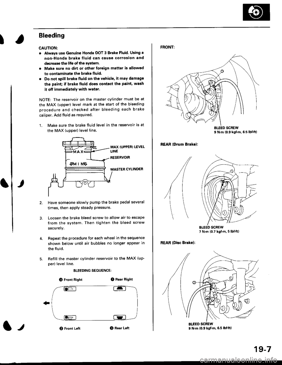
I
Bleeding
CAUTION:
. Always use Genuine Honda DOT 3 Brake Fluid. Using 8
non-Honda brak€ fluid can cause corrosion and
docrea3e the life of the system.
. Make surs ||o dirt or other foteign matter is allowed
to contaminate the brake fluid,
. Do not spill brake lluid on the vehicle, it may damago
the paint; if brake lluid doos contac{ the paint, wash
it ofl imm€diately with water.
NOTE: The reservoir on the master cylinder must be at
the MAX (upper) level mark at the start of the bleeding
procedure and checked after bleeding each brake
caliper. Add fluid as required.
1. Make sure the brake fluid level in the reservoir is at
the MAX lupper) level line.
MAX {UPPER) LEVEL
CYLINDER
Have someone slowly pump the brake pedsl several
times, then apply steady Pressure.
Loosen the brake bleed screw to allow air to escape
from the system. Then tighten the bleed screw
securely.
Repeat the procedure for each wheel in the sequence
shown below until air bubbles no longer appear in
the fluid.
Refill the master cylinder reservoir to the MAX (up-
per) level line.
ELEEDING SEOUENCE:
O Front Right(D Bo.r Right
O Front LeftO Rear Left1,,
19-7
FRONTT
REAR lDrum Brakel:
REAR (Disc Brake):
AIEED SCREW9 N.m (0.9 ksf m, 6.5 lbf'ft)
Page 1177 of 2189
Brake Booster InsPection
FunctionalTest
1. With the engine stopped, depress the brake pedal
several times to deplete the vacuum reservoir, then
depress the pedal hard and hold it for 15 seconds lf
the pedal sinks' either the master cYlinder is
bypassing internally, or the brake system (master
cylinder. lines. modulator, proportioning control
valve, or caliPer) is ieaking.
2. Start the engine with the pedal depressed lf the
pedal sinks slightly, the vacuum booster is operating
normally. lf the pedal height does not vary, the
booster or check valve is faultY.
3. With the engine running. depress the brake pedal
lightly. Apply just enough pressure to hold back
automatic transmission creep. lf the brake pedal
sinks more than 25 mm (1.0 in.) in three minutes,
the master cvlinder is faulty. A slight change in
pedal height when the A'lC compressor cycles on
and off if normal. (The A/C compressor load
changes the vacuum available to the booster')
Leak Test
1. Depress the brake pedal with the engine running.
then stop the engine. lf the pedal height does not
vary while depressed for 30 seconds, the vacuum
booster is OK. lf the pedal rises. the booster is
faulty.
2, With the engine stopped, depress the brake pedal
several times using normal pressure When the
Dedal is first depressed, it should be low On con-
secutive applications, the pedal height should grad-
uallv rise. lf the pedal position does not vary, checK
the booster check valve.
l./
19-23
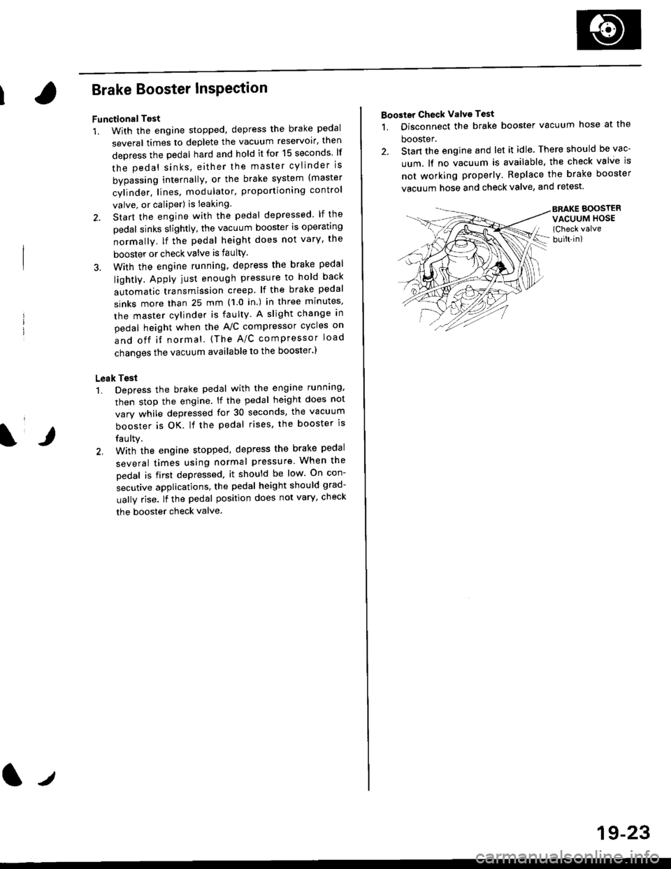
Booster Check Valve Test
1. Disconnect the brake booster vacuum hose at the
booster.
2. Stan the engine and let it idle. There should be vac-
uum. lf no vacuum is available, the check valve is
not working properly. Replace the brake booster
vacuum hose and check valve, and retest.
BRAKE BOOSTERVACUUM HOSE(Check valve
built-in)
Page 1199 of 2189
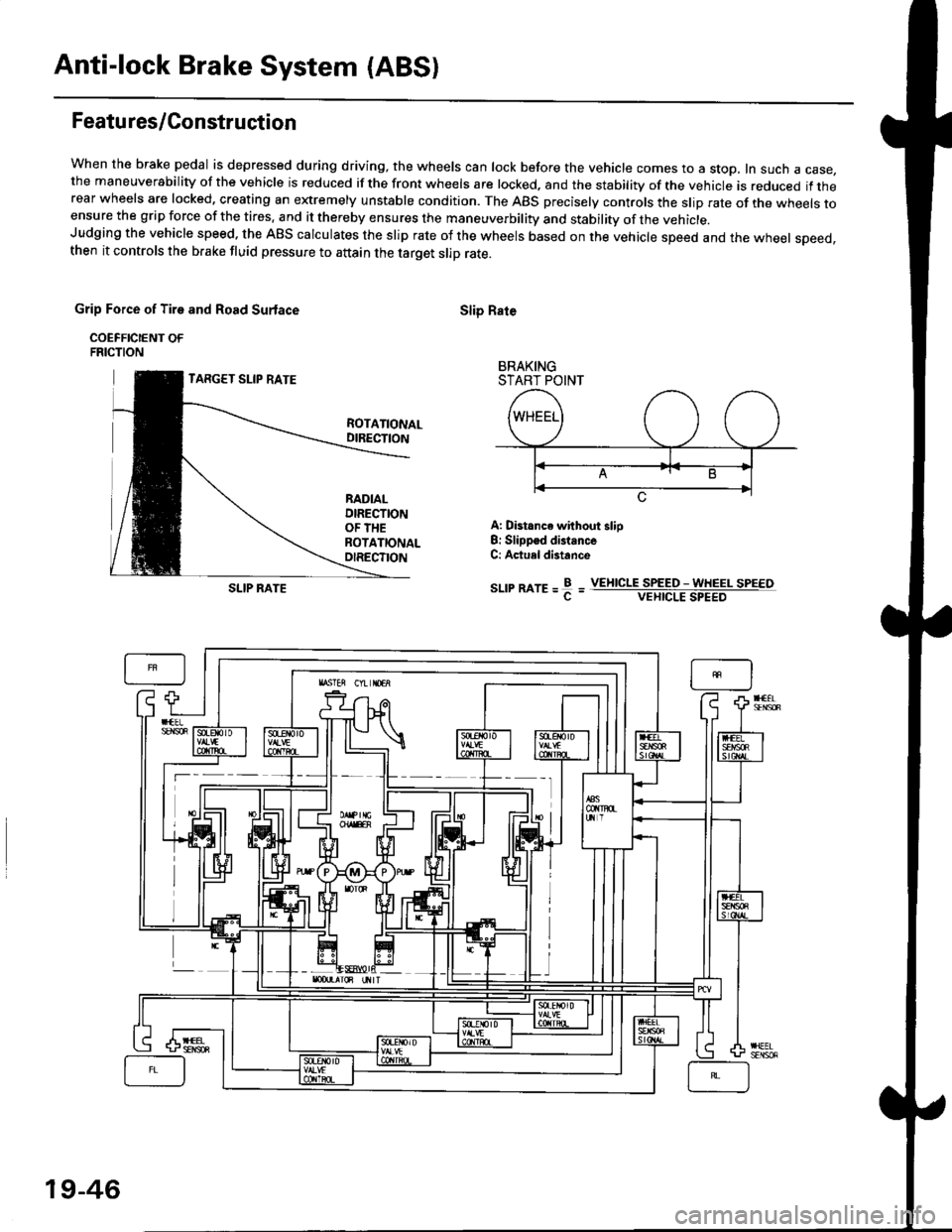
Anti-lock Brake System (ABSI
Featu res/Construction
When the brake pedal is depressed during driving, the wheels can lock before the vehicle comes to a stop, In such a case,the maneuverability of the vehicle is reduced if the front wheels are locked, and the stability of the vehicle is reduced if therear wheels are locked, creating an extremely unstable condition. The ABS precisely controls the slip rate of the wheels toensure the grip force of the tires. and it thereby ensures the maneuverbility and stability of the vehicle.Judging the vehicle speed. the ABS calculates the slip rate of the wheels based on the vehicle speed and the wheel speed,then it controls the brake fluid pressure to attain the target slip rate.
Grip Force of Tire and Road Surlace
COEFFICIENT OFFRICTION
TARGET SLIP RATE
Slip Rate
BRAKINGSTART POINT
ROTATIONALDIRECTION
RADIALDIRECTIONOF THEROTATIONALOIRECTION
A: Distance without slio8: Slippsd distanceC: Actuel distance
sr-rrmre=f=SLIP RATEVEIIICLE SPEED - WHEEL SPEEOVEHICLE SPEED
19-46