Page 1345 of 2189

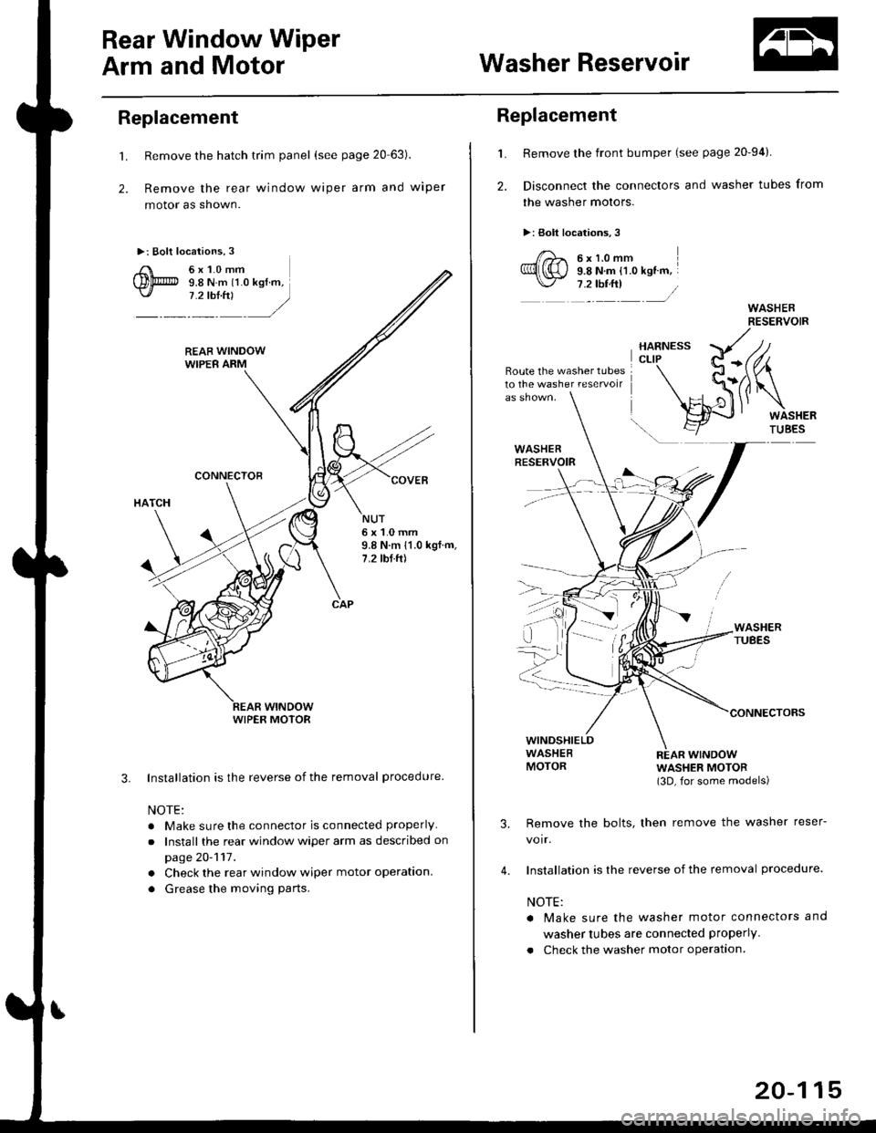
Rear Window Wiper
Arm and MotorWasher Reservoir
Replacement
't.
2.
Remove the hatch trim panel (see page 20 63).
Remove the rear window wiper arm and wiper
motor as shown.
Installation is the reverse of the removal procedure
NOTE:
. Make sure the connector is connected properly
.Install the rear window wiper arm as described on
page 20-117.
. Check the rear window wiper motor operation.
. Grease the moving parts.
3.
NUT6x1.0mm9.8 N.m 11.0 kgf.m,7.2 tbf.ft)
WIPER MOTOR
L
2.
Replacement
Remove the front bumper (see page 20-94).
Disconnect the connectors and washer tubes from
the washer motors.
>: Bolt locations,3
/)^ 6xt.omm
Ql(S) s.e ru.- tt.o ret '".\./ 7 .2 tbf.ft) /
Route the washer tubes10 the washe. reservoir
wtNDowWASHER MOTOR(3D, for some models)
Remove the bolts, then remove the washer reser-
voir.
Installation is the reverse of the removal procedure.
NOTE:
a Make sure the washer motor connectors and
washer tubes are connected properly.
. Check the washer motor operation.
3.
4.
20-115
Page 1347 of 2189

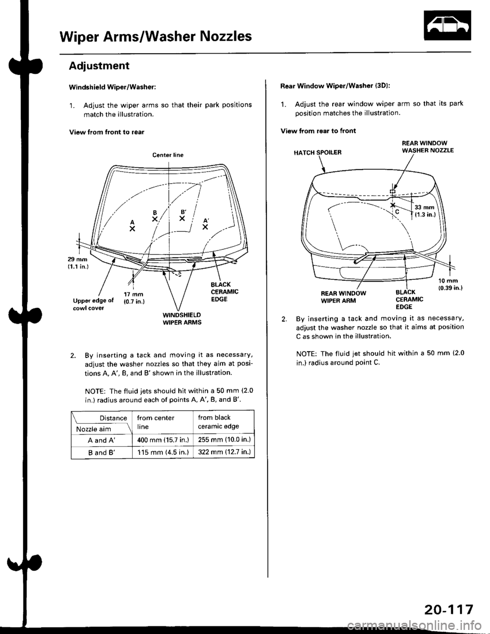
Wiper Arms/Washer Nozzles
Adjustment
Windshield wiper/Washer:
1. Adjust the wiper arms so that their park positions
match the illustration.
View trom tront to rear
WINDSHIELDWIPER ARMS
2. By inserting a tack and moving it as necessary,
adjust the washer nozzles so that they aim at posi-
tions A, A', B, and B'shown in the illustration.
NOTE: The fiuid jets should hit within a 50 mm (2 0
in.) radius around each of points A, A', B, and B'.
.// \
A'x..
-.4
,'lxiAx
Distance
M;r.";-lll
from center
lrne
from black
ceramrc eoge
A and A'400 mm (15.7 in.)255 mm (10.0 in.)
B and B'115 mm (4.5 in.)322 mm \12.7 in.)
Rear Window wiper/Washer (3Dl:
1. Adjust the rear window wiper arm so that its park
position matches the illustration.
View trom raar to front
CERAMICEDGE
By inserting a tack and moving it as necessary,
adjust the washer nozzle so that it aims at position
C as shown in the illustration.
NOTE: The fluid jet should hit within a 50 mm (2.0
in,) radius around point C.
REAR WINOOWWIPER ARM
r-
---..J_.__11,:l
20-117
Page 1352 of 2189
Body ('97 model)
Front Seat Belt
Removal/lnstallatlon ....20-128
Rear Seat
RemovaUlnstallation ....20-126
Washer Tube
Windshield
fndex .......... 20-124
Outline of '97 Model Changes
The molding side seal was added.
The method of installing the rear seat cushion was changed (2Dl3D).
A middle floor gusset was added and the method of detaching the seat belt retractor was changed (2Dl3D)
The installation position of the washer tube was changed.
Page 1357 of 2189

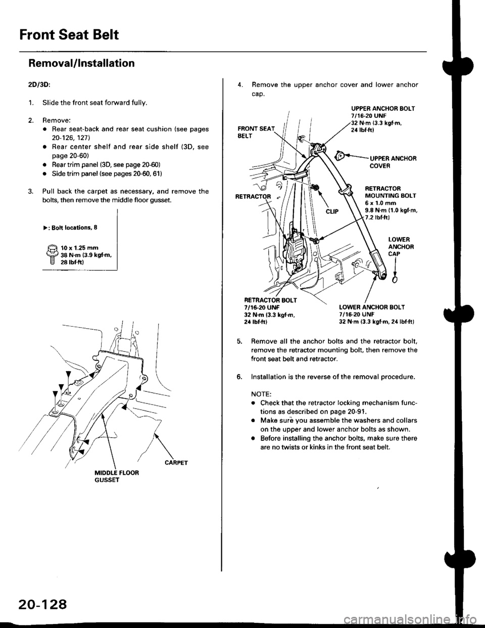
Front Seat Belt
RemovaUlnstallation
2D l3Dl
1. Slide the front seat forward fully.
2. Remove:
. Rear seat-back and rear seat cushion (see pages
20-126,127l.
. Rear center shelf and rear side shelf (3D, see
page 20-60)
. Resr trim panel (3D, see page 2G60)
. Side trim panel (see pages 20-60, 61)
3. Pull back the carpet as necessary, and remove the
bolts, then remove the middle floor gusset.
>: Boh locations,8
10 x 1.25 mm38 N.m (3.9 kgf'm,28 rbtftl
20-124
4. Remove the upper anchor cover and lower anchor
cap.
UPPER ANCHOR EOLT7/16-20 UNF32 N.m {3.3 kgf.m,24 tbf.ftt
UPPER ANCHORCOVER
LOWERANCHOBCAPIIio
RETRACTORMOUNTING BOLT6x1.0mm9.8 N.m (1.0 kgf.m.7.2 tbl.hl
LOWER ANCHOR BOLT7/16-20 UNF32 N.m (3.3 kgt.m, 24 lbf.ft)
Remove all the anchor bolts and the retractor bolt.
remove the retractor mounting bolt, then remove the
Iront seat belt and retractor.
Installation is the reverse of the removal orocedure.
NOTE:
. Check that the retractor locking mechanism func-
tions as described on page 20-91
o Make suri vou assemble the washers and collars
on the upper and lower anchor bolts as shown.
. Before installing the anchor bolts, make sure there
are no twists or kinks in the front seat belt.
RETRACTOR AOLT7/16-20 UNF32 N.m 13.3 kgf.m,24 tbttrl
6.
Page 1364 of 2189
Body ('99 model)
Dashboard
Center Panel Removal and
lnstallation
Bumpers
Front Grille Removal and
lnstallation
Front Air Spoiler Replacement ."'.....
Seats
Front Seat DisassemblY and
ReassemblY 20-138
Front Seat Torsion Bar
Replacement '.'...".'....'... 20-139
Emblems
tnstallation 20-140
20-136
20-136
20-137
Outline of '99 Model Changes
The center Danel removal and installation procedures are different'
The front grille removal and installation procedures are different'
The front air spoiler has been added for some models of 2D'
A height-adjustable driver's seat was added to some models'
Emblems were added for some models ot 2D'
Page 1365 of 2189
DashboardBumpers
I
Center Panel Removal and
Installation
1. Remove the dashboard center lower cover.
2. Remove the screws, then pull out the center panel.
>: Sc.ew locationi,4 >: Clip locationsA >,3B>,4rl
@Y,
UPPER VENT I(NOB
Disconnect the connectors from the heater controlunit and hazard warning switch.
Installation is the reverse of the removal procedure.
NOTE: Make sure the connectors are connectedpropefly.
20-136
Installation is the reverse of the removal procedure.
FRONT BUMPER
a&
Front Grille Removal and
Installation
NOTE: Take care not to scratch the front bumper.
Remove the front bumper. Remove the screws. thenslide the front grille forward by detaching the hooks.
>: Scrow locltion3,6
I
dbp i
Page 1366 of 2189
Front Air SPoiler RePlacement
CAUTION: Put on gloves to protect your hands'
NOTE:
. An assistant is helpful when removing the front bumper'
. Take care not to scratch the front bumper and body'
>: Bolt, screw localions
A >,9 B >,4
s*i@l
BUMPER
lnstallation is the reverse of the removal procedure'
NOTE:
. Make sure the front bumper engages the front
bumper side stiffener on each side securely'
o lf necessary. adjustthe front bumper side stiffener
to obtain the Proper gap.
FRONT AIR SPOILER
20-137
Page 1367 of 2189
Seats
Front Seat Disassembly and Reassembly
CAUTION: When prying with a flat-tip screwdriver, wrap it with protective tape to prevent damage.
NOTE: SEAT-BACK. Take care not to scratch the seat covers and body.. Remove the front seat through the door openlng.
Driver's:
SEAT CUSHION
HEADREST
PIVOT NUTI x 1.25 mm22 N.m 12.2 kgf,m,16 tbf.ft)
CENTER COVER
8 x 1.25 mm
LOWER CAP
RECLINE ADJUSTER
WASHER
20 N.m 12.0 kgf.m,lil lbtftl
WASHERS
EUSHING
10 x 1.25 mm47 N.m (4.8 kgf.m,3s rbl.ft)
INNER SEATTRACKRECLINECOVER
WASHER
8 x 1.25 mm20 N.m (2.0 kg,f.m,14 tbf.fit
LOWER CAPI
8 x 1.25 mm20 N.m {2.0 kgI.rn,l4 tbf.ft)
i\",-,"
20-13A
HEIGHT HANDLE