Page 1317 of 2189

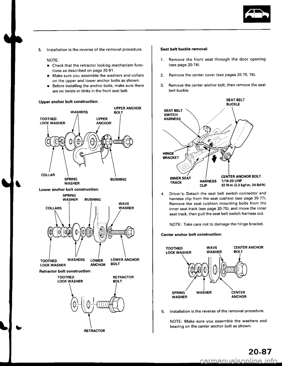
5. Installation is the reverse of the removal procedure.
NOTE:
. Check that the retractor locking mechanism func-
tions as described on page 20-91.
. Make sure you assemble the washers and collars
on the uoDer and lower anchor bolts as shown.
. Before installing the anchor bolts, make sure there
are no twists or kinks in the front seat belt.
SPRINGWASHER
Lower anchor bolt construction:
SPRINGWASHER BUSHING
BUSHING
COLLARS
LOCKWASHER ANCHOR
Reiractor bolt construction:
TOOTHEOLOCK WASHER
WASHERS LowERLOWER ANCHORBOLT
RETRACTOB
Seat belt buckle removal:
1. Remove the front seat through the door opening
{see page 20-74).
2. Remove the center cover (see pages 20-75,76).
3. Remove the center anchor bolt, then remove the seat
belt buckle.
SEAT BELTBUCKLE
ANCHOR BOLTINNER SEATTRACK
TOOTHEOLOCK WASHER
SPRINGWASHER
HARNESS 7/16.20 UNF
CLIP 32 N m (3.3 kgt m, 24 lbf'ft)
4. Driver's: Detach the seat belt switch connector and
harness clip from the seat cushion (see page 20 77).
Remove the seat cushion mounting bolts from the
inner seat track {see page 20-75), and move the inner
seat track, then pull the seat belt switch harness out.
NOTE: Take care not to damage the hinge bracket.
Centsr anchor bolt construction:
CENTER ANCHORBOLT
WASHER
Installation is the reverse of the removal procedure.
NOTE: Make sure you assemble the washers and
bearing on the center anchor bolt as shown.
20-47
Page 1321 of 2189

Seat Belts
Inspection
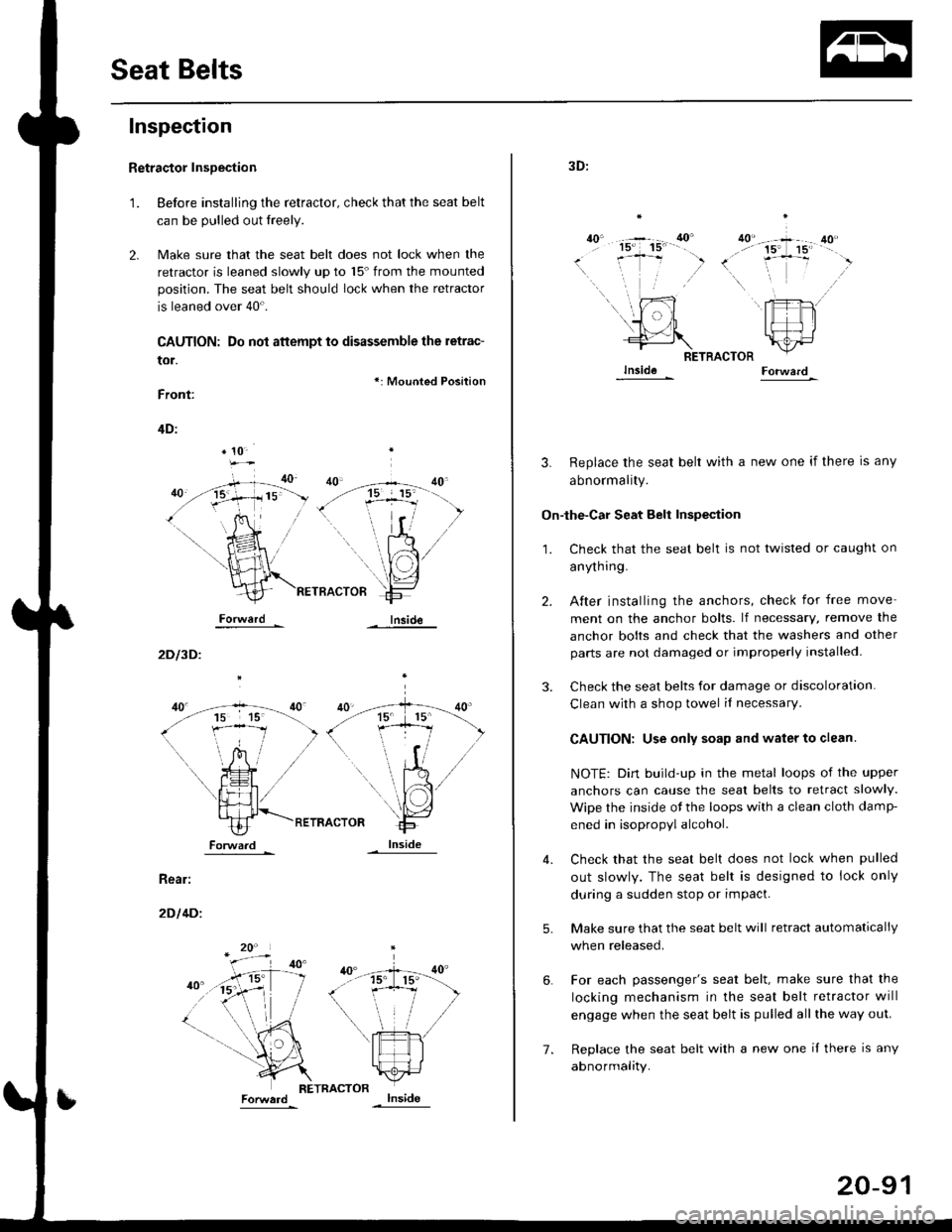
t.
Retractor InsDection
Before installing the retractor, check that the seat belt
can be pulled out freely.
Make sure that the seat belt does not lock when the
retractor is leaned slowly up to 15'from the mounted
position. The seat belt should lock when the retractor
is leaned over 40'.
CAUTION: Do not attempt to disassemble the retrac-
tor.
Front:
*: Mounted Position
Inside
4D:
Forward
2D l3D.
Rear:
2D l4Di
* 10-
15 15'
i-Tl
I ],f
ForwaJdlnside
7.
20-91
3D:
ao"40'- -+ 40...'' 15' 15' --
(. .-j- ,)\,
RETRACTOR
3. Replace the seat belt with a new one if there is any
abnormality.
On-lhe-Car Seat Belt Inspeqtion
2.
3.
1.
5.
6.
4.
Check that the seat belt is not twisted or caught on
anyrn I ng.
After installing the anchors, check for free move
ment on the anchor bolts. lf necessary, remove the
anchor bolts and check that the washers and other
parts are not damaged or improperly installed
Check the seat belts for damage or discoloration.
Clean with a shop towel il necessary
CAUTION: Use only soap and water to clean.
NOTE: Dirt build-up in the metal loops of the upper
anchors can cause the seat belts to retract slowly.
Wipe the inside ot the loops with a clean cloth damF
ened in isopropyl alcohol.
Check that the seat belt does not lock when pulled
out slowly. The seat belt is designed to lock only
during a sudden stop or impact.
Make sure that the seat belt will retract automatically
when released.
For each passenger's seat belt, make sure that the
locking mechanism in the seat belt retractor will
engage when the seat belt is pulled all the way out.
Replace the seat belt with a new one il there is any
abnormality.
Page 1324 of 2189
Front Bumper
Replacement
CAUTION: Put on glov$ to protect your hands.
NOTE:
. An assistant is helpful when removing the front bumper.
. Take care not to scratch the front bumDer and bodv.
FRONT BUMPERSIDE SNFFENER
lnstallation is the reverse of the removal orocedure.
NOTE:
. Make sure the front bumper engages the front
bumper side stiffener on each side securely.
. lf necessary, adjust the front bumper side stiffener
to obtain the proper gap.
>: golt, screw locationsa>,2B>,2>: Cliplocations, 7
iAerr:ore. A lm
L.'* fl'T;Ll'
o'n' -'
\€5>_ JIc>,4 ,D>,4
| -.6a 8 x 't.25 mm l,Rt o x 1.0 mm
l(Dl[m 22N.n'.t2.2kstnf'. j(Qll@ s.e N.m rr.o rsf.m,t'KJ) 16 tbf.ft, |. -ll 7.2 tbf.hJ
ABSORBER
FRONT EUMPERBEAM
FRONT BUMPERSIDE STIFFENER
FRONT BUMPER BEAM
:l
I ir
\
20-94
Page 1326 of 2189
Hood
Adjustment
NOTE: Before adjusting the hood, loosen each bolt slightly.
1. Adjust the hood hinges right and left, as well as fore and aft, by using the elongated holes.
2. Turn the hood edge cushions, as necessary. to make the hood fit flush with the body at front and side edges.
3, Adjust the hood latch to obtain the proper height at the forward edge.
4. After adjustment, tighten each bolt securely.
6x1.0mm9.8 N.m {1.0 kgt.m,7.2 tbt.tll
NOTE: Move the hood latch right or left
is centered in the hood latch as shown.
)
until the striker
6x1.0mm9.8 N.m {1.0 kgf.m,7.2 tbf.ftl
\
20-96
Page 1329 of 2189
Front Grille/Hood Edge
Protector
Trunk Lid Torsion
Bars
Replacement
Front grille:
NOTE: Take care not to scratch the front bumper'
Remove the front bumper (see page 20-94) Bemove the
clips and screws, then slide the front grille forward by
detaching the hooks.
>: Screw locations, 4
"qL
A +lt /
Hood edge Ploteetor:
NOTE:
. When removing the clips, use a cllp remover.
. lf necessary, replace any damaged clips.
>:Clip locations, 18
FRONT BUMPER
HOOD EDGE
/A.- -----,_ ,,, \-'-l
o[_]
20-99
Removal
CAUTION: Pui on gloves to protect your hands.
NOTE: Take care not to damage the body
Remove the torsion bars with the torsion bar assembly
tool while holding the trunk lid as shown.
CENTER CLIP
E
lnstallation is the reverse of the removal procedure'
NOTE:
. Adjust the torsion bars fore or aft with the
sion bar assemblY tool as shown
ll = Normal Posrtlona = Higher tensron
. Make sure the trunk lid opens properly.
tor-
Page 1333 of 2189
Door and Side Moldings
Replacement
CAUTION: When prying with a flat-tip scr6wdrivgr, wrap it with protective tape to prevent damags'
NOTE;
. To remove the front side molding, remove the inner fender (see page 20-106)'
. To remove the door moiding, remove the door panel (see pages 20-4, 10, 16) and plastic cover.
. To removethe rearside molding, remove the side trim panel (see pages 20-60,611'
. Take care not to bend the door moldings.
. Before reassembling, clean the door bonding surface with a sponge dampened in alcohol'
. After cleaning, keep oil, grease and water from getting on the surface'
. lf necessary, replace any damaged clips.
4D:
FRONT DOORAdhesive areas.
2Dl3Dl
B>,3c>,2
REAR SIDEMOLOING
a: Plastic nut loc€tion. 1
@)
(cont'dl
20-103
MOLDING
>: Clip locations
A >: 4D, 112')13D,7
Page 1338 of 2189

Opener Cables
Replacement
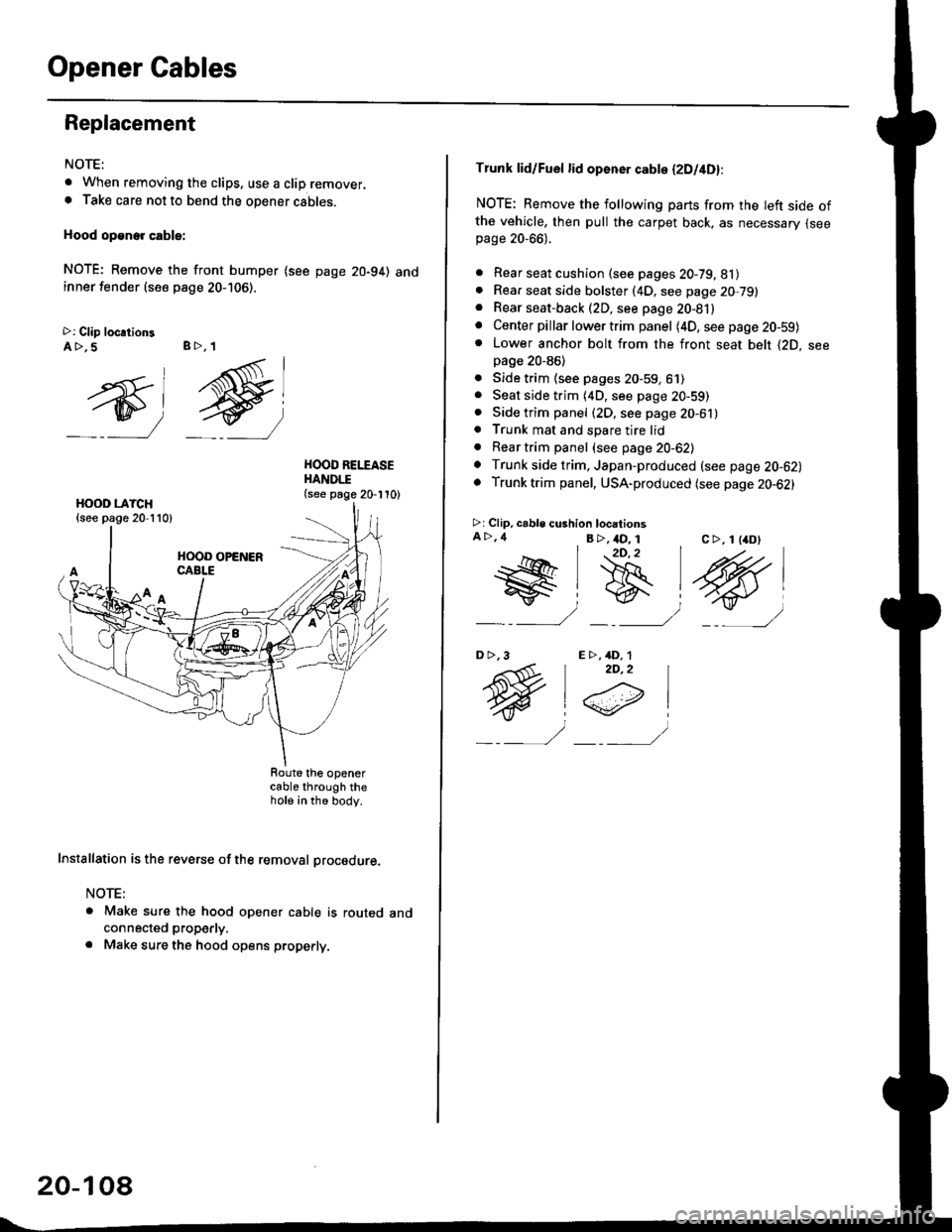
NOTE:
t When removing the clips. use a clip remover.. Take care not to bend the opener cables.
Hood op€ne. cable:
NOTE; Remove the front bumper (see page 20-94) andinner fender (see page 20-106).
>: Clip loc.tionsA >,5 B>, 1
ry)
g
HOOD REI.TASEHANDI.I(see page 20-110)
cable through thehote in th6 body.
Installation is the reverse of the removal procedure.
NOTE:
a Make sure the hood opener cable is routed andconnected properly.
. Make sure the hood opens properly.
20-10a
Tlunk lid/Fuel lid opener cabte (2Dl4D):
NOTE: Remove the following parts from rhe Ieft side ofthe vehicle, then pull the carpet back, as necessary {seepage 20-66).
. Rear seat cushion (see pages 20-79, 81). Rear seat side bolster (4D, see page 20,79). Rear seat-back (2D, see page 20-81). Center pillar lower trim panel (4D, seepage20-59)o Lower anchor bolt from the front seat belt {2D. seepage 20-86)
. Side trim (see pages 20-59, 61). Seat side trim (4D, see page 20-59). Side trim panel (2D, see page 20-61). Trunk mat and spare tire lid. Reartrim panel (see page 20-62). Trunk side trim, Japan-produced (see page 20-62). Trunk trim panel, USA-produced (see page 20-62)
>r Clip, cable cushion locationsA >,4 B >,4D_ 1c >, 1 l4D)2D,2
t@#lB
_ : _/ _-___)
E >,4D, 12D,2
@i
_ _,, -/
D>,3
Page 1340 of 2189

Opener CablesOpener and Latch
Replacement (cont'dl
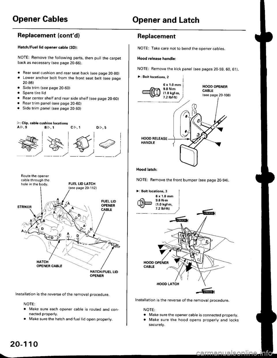
Hatch/Fuel lid opener cable l3Dl:
NOTE: Remove the following parts, then pull the carpetback as necessary (see page 20-66).
. Rear seat cushion and rear seat back (see page 20-80). Lower anchor bolt from the front seat belt (see page
20 86)
. Side trim {see page 20-60). Spare tire lid
. Rear center shelf and rear side shelf {see page 20-60). Rear trim panel (see page 20-60). Side trim panel (see page 20,60)
>: Clip, cable cushion locationsa>.9B>, 1c>, 1D >,5
W#)
FUEL LID LATCH
#,
Route the openercable through thehole in the body.
HATCH/FUEL LIOOPENER
Installation is the reverse of the removal procedure.
NOTE:
. Make sure each opener cable is routed and con-nected properly.
. Make sure the hatch and fuel lid open properly.
page 20-112)
20-110
6x1.0mm j9.8Nm{1.0 kgf.m, i
Replacement
NOTE: Take care not to bend the opener cables.
Hood release handle:
NOTE: Remove the kick panel (see pages 20-59, 60.61).
>: Bolt locations, 2 ]I
HOOO OPENERCABLE(see page 20-108)
Hood latch:
NOTE: Remove the front bumper (see page 20-94).
>: Eolt locations, 3 I6 x '1.0 mm9.8 N.m11.0 kgf.m,
Installation is the reverse of the removal procedure.
NOTE:
. Make sure the opener cable is connected properly.. Make sure the hood opens properly and locks
securely.