Page 1747 of 2189
)
Wiring Precautions
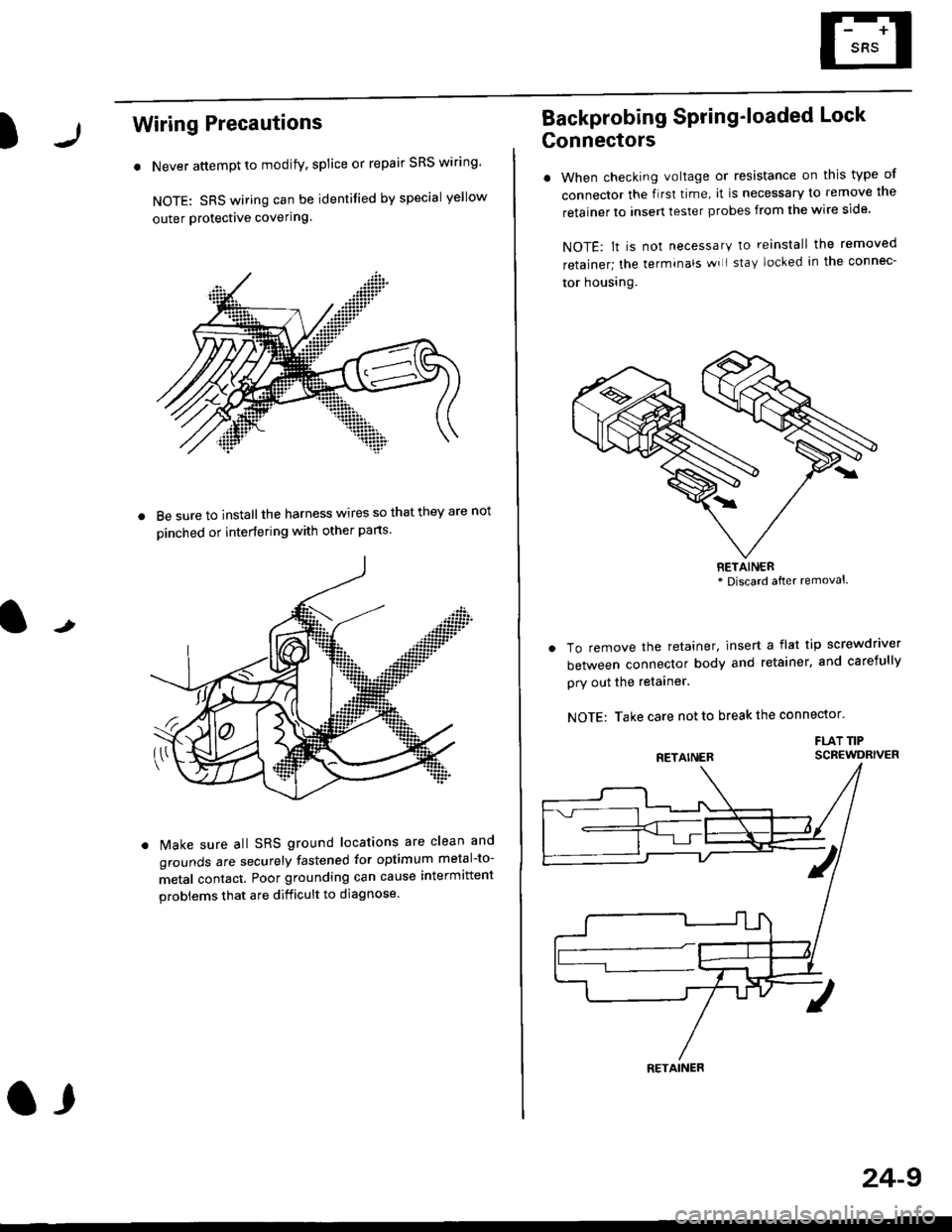
. Never attempt to modify, splice or repair SRS wiring'
NOTE: SRS wiring can be identified by special yellow
outer Protective covering.
8e sure to install the harness wires so that they are not
oinched or interfering with other parts.
t
Make sure all SRS ground locations are clean and
grounds are securely fastened for optimum metal-to-
metal contact. Poor grounding can cause intermittent
problems that are difficult to diagnose.
a,
24-9
Backprobing Spring'loaded Lock
Gonnectors
. When checking voltage or resistance on this type of
connector the flrst time, it is necessary to remove lne
retainer to insert tester probes from the wire side.
NOTE: lt is not necessary to reinstall the removed
retainer; the terminals wi I stay locked in the connec-
tor housrng.
To remove the retainer, insert a flat tip screwdriver
between connector body and retainer, and carefully
pry out the retainer.
NOTE: Take care not to break the connector.
FLAT TIPSCBEWDRIVER
RETAINER* Discard after removal.
RETAINER
Page 1831 of 2189
How To Use This Manual
Troubleshooting Tests
Testing for Voltage Drop
Wires, connectors, and switches are designed
to conduct current wilh a minimum loss of
voltage. A voltage drop of more than one volt
indicates a Droblem.
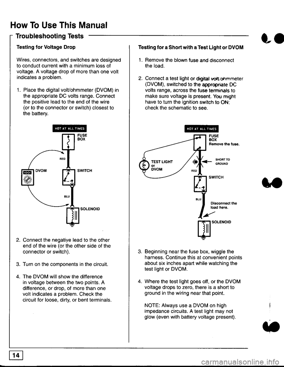
'1. Place the digital volVohmmeter (DVOM) in
the appropriate DC volts range. Connect
the positive lead to the end of the wire
(or to the connector or switch) closest to
the bafterv.
Connect the negative lead to the other
end of the wire (or the other side of the
connector or switch).
Turn on the components in the circuit.
The DVOM will show the difference
in voltage between the two points. A
difference, or drop, of more than one
volt indicates a oroblem. Check the
circuit for loose, dirty, or bent terminals.
co
Testing lor a Short with a Test Light or DVOM
1. Remove the blown fuse and disconnect
the load.
2. Connect a test light or digital
oltr'ohmmeter
(DVOM), switched to the appropnare DC
volts range, across the tuse lerminals to
make sure voltage is present. You might
have to turn the ignition switch to ON:
check the schematic to see.
<-s80RT TOGFOUNO
Disconnecl lheload here.
Beginning near the luse box, wiggle the
harness. Continue this at convenient ooints
about six inches apart while watching the
test light or DVOM.
Where the test light goes off, or the DVOM
voltage drops to zero, there is a short to
ground in the wiring near that point.
NOTE: Always use a DVOM on high
impedance circuits. A test light may not
glow (even with battery voltage present).
3'�'
ffito.'"o'o
.t.
TEST LIGHTolDVOM
Page 1832 of 2189
Testing for a Short with a Sell-Powered
Test Light or DVOM
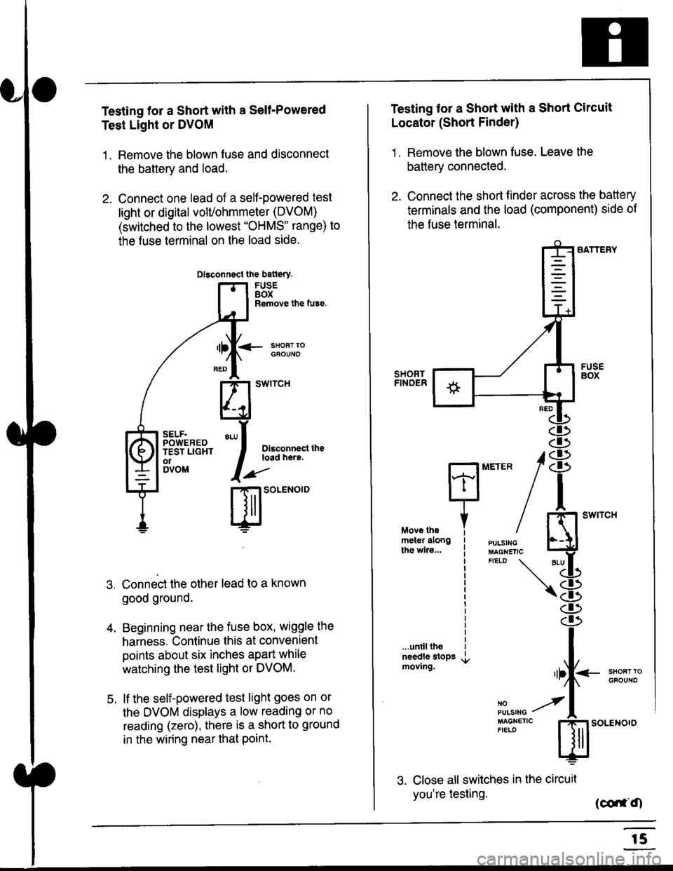
1. Remove the blown fuse and disconnect
the battery and load.
2. Connect one lead of a self-powered test
light or digital volUohmmeter (DVOM)
(switched to the lowest "OHMS" range) to
the fuse terminal on the load side.
Dlsconnect the batlery.
FUSEBOXRemove the fuse.
<- ssoRr rociouNo
Dlsconnect theload here.
.)"'
r| SOLENOID
Connect the other lead to a known
good ground.
Beginning near the fuse box, wiggle the
harness. Continue this at convenient
points about six inches apart while
watching the test light or DVOM.
lf the self-powered test light goes on or
the DVOM displays a low reading or no
reading (zero), there is a short to ground
in the wiring near that Point.
SELF.POWEREDTEST LIGHTo1DVOM
4.
5.
Testing tor a Short with a Short Circuit
Locator (Short Finder)
1 . Remove the blown fuse. Leave the
battery connected.
2. Connect the short finder across the battery
terminals and the load (component) side of
the fuse terminal.
SATTERY
SHORTFINOER
FUSEBOX
PULSINGMAGNETICFIELD \
NOPUISING
\
I swtrcH
I
<- stl
Kl"I- -.T.1
"'at
\8
d)
.r.
rlll<
,l
m
...unilltheneedle slopsmoving.SHOFTTGFOUNO'llt
No --tPULS|NG z
MAGNETTC IFIELD ISoLENOTO
3. Close all switches in the circuil
you're testing. (co,f,O
r5
Page 2030 of 2189
Power Door Locks (cont'd)
Keyless Entry Does Not Work In Any
Mode
NOTE: Before beginning, verify that all the
transmitters are programmed to the vehicle.
1 . Does the radio work properly?
Yes - Go to step 9.
No - Go to the neld step.
NOTE: For steos 2 - 8. refer to the schematic dia-
gram for the Stereo Sound System on page 150.
2. Are fuses 28 (in the under-dash fuse box) and
fuse 47 (in the under-hood fuse box) OK?
Yes - Go to step 4.
No - Replace the blown fuse, then go to the
nen steo.
3. Does the fuse blow again?
Yes - Locate and repair the short.
No- Retest the system.
4. ls the vehicle equipped with the optional security
system?
Yes - Go to the next steP.
No - Go to steD 6.
5. Does the keyless entry work correctly when the
security control unit connector is disconnected?
Yes - Faulty security system, go to security
system for f urther troubleshooting.
No - Go to the next step.
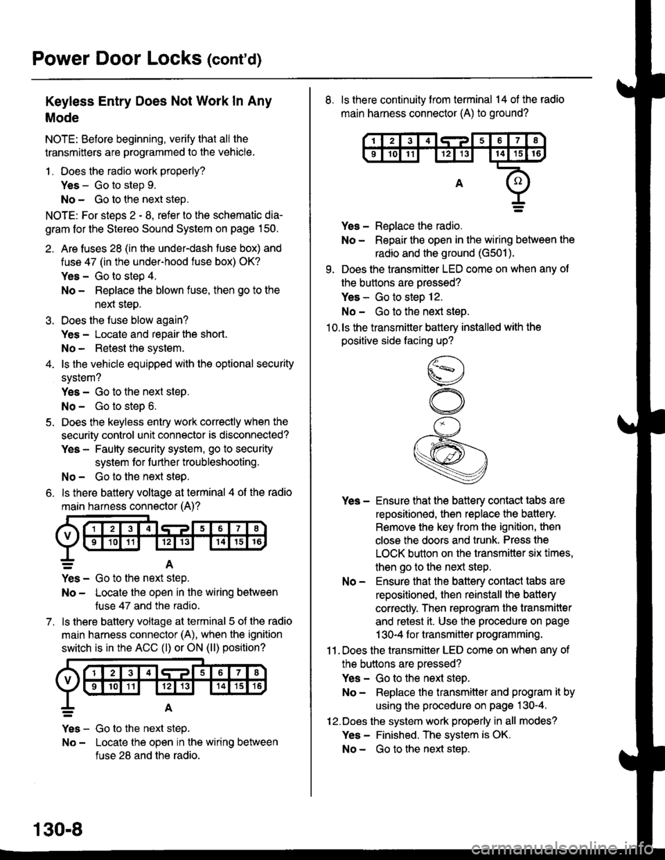
6. ls there battery voltage at terminal 4 of the radio
main harness connector (A)?
7.
=A
Yes - Go to the nen step.
No - Locate the open in the wiring between
tuse 47 and the radio.
ls there battery voltage at terminal 5 of the radio
main harness connector (A), when the ignition
switch is in the ACC (l) or ON (ll) position?
Yes - Go to the next step.
No - Locate the open in the wiring between
fuse 28 and the radio.
130-8
8. ls there continuity from terminal 14 of the radio
main harness connector (A) to ground?
Yes - Replace the radio.
No - Repair the open in the wiring between the
radio and the ground (G501).
9. Does the transmitter LED come on when any ot
the buttons are oressed?
Yes - Go to steo 12.
No - Go to the next steo.'10.ls the transmitter battery installed with the
positive side facing up?
Yes - Ensure that the battery contact tabs are
repositioned, then replace the battery.
Remove the key from the ignition, then
close the doors and trunk. Press the
LOCK button on the transmitter six times,
then go to the next step.
No - Ensure that the baftery contact tabs are
repositioned, then reinstall the batlery
correctly. Then reprogram the transmitter
and retest it. Use the procedure on page
1 30-4 f or transmitter programming.
11 . Does the transmitter LED come on when any of
the buttons are oressed?
Yes - Go to the next step.
No - Replace the transmitter and program it by
using the procedure on page 130-4.
12.Does the system work properly in all modes?
Yes - Finished. The system is OK.
No - Go to the next steD.
Page 2059 of 2189
\.
\iu
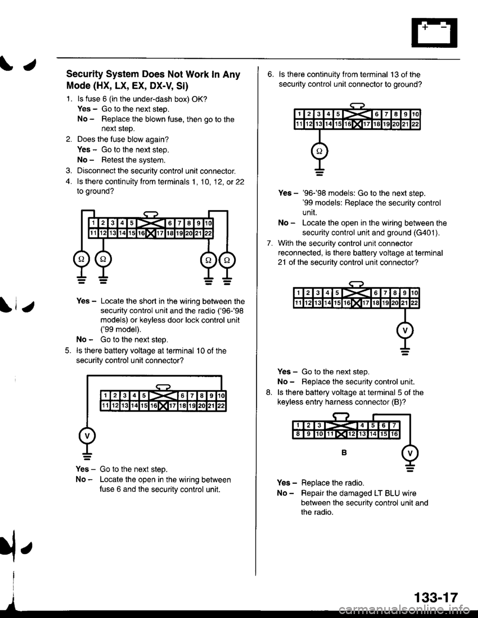
Security System Does Not Work In Any
Mode (HX, LX, EX, DX-V, Si)
1. ls fuse 6 (in the under-dash box) OK?
Yes - Go to the next steo.
No - Replace the blown tuse, then go to the
next sleD.
2. Does the fuse blow again?
Yes - Go to the next step.
No - Retest the system.
3. Disconnect the security control unit connector.
4. ls there continuity from terminals 1, 10, 12, ot 22
to oround?
5.
Yes - Locate the short in the wiring between the
security control unit and the radio ('96-'98
models) or keyless door lock control unit
('99 model).
No - Go to the next step.
ls there battery voltage at terminal 10 of the
securitv control unil connector?
Yes - Go to the next steo.
No - Locate the open in the wiring between
fuse 6 and the securitv control unit.
133-17
rfe
6. ls there continuity f rom terminal 13 ot the
security control unit connector to ground?
7.
Yes - '96-'98 models: Go to the next steD.'99 models: Replace the security control
unit.
No - Locate the open in the wiring between the
security control unit and ground (G401 ).
With the security control unil connector
reconnected, is there battery voltage at terminal
21 ot the securitv control unit connector?
Yes - Go to the next step.
No- Beplace the security control unit.
ls there battery voltage at terminal 5 of the
keyless entry harness connector (B)?
Yes - Replace the radio.
No- Repair the damaged LT BLU wire
between the security control unit and
the radio.
8.
Page 2063 of 2189
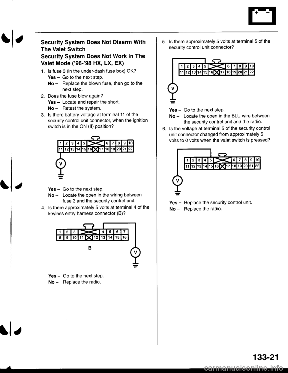
rl,Security System Does Not Disarm With
The Valet Switch
Security System Does Not Work ln The
Valet Mode ('96-'98 HX, LX, EX)
1. ls luse 3 (in the under-dash fuse box) OK?
Yes - Go to the next steD.
No - Replace the blown fuse, then go to the
next step.
2. Does the fuse blow again?
Yes - Locate and reoair the short.
No - Retest the system.
3. ls there battery voltage at terminal 11 of the
security control unit connecto( when the ignition
switch is in the ON (ll) position?
Yes - Go to the next step.
No - Locate the open in the wiring between
luse 3 and the security control unit.
ls lhere approximately 5 volts at terminal 4 of the
keyless entry harness connector (B)?
Yes - Go to the next step.
No - Replace the radio.
rl e
133-21
5. ls there approximately 5 volts at terminal 5 of the
security control unit connector?
Yes - Go to the next step.
No - Locate the open in the BLU wire between
the security control unit and the radio.
ls the voltage at terminal 5 oJ the security control
unit connector changed from approximately 5
volts to 0 volts when the valet switch is pressed?
Yes - Replace the security control unit.
No - ReDlace the radio.
6.