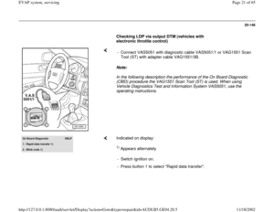
Page 49 of 65
Setting mode.
VAS 5051 should immediately indicate "System
OK"
- Repeat test several times to verify result.
If test continues to indicate "System OK",
remove clamp and proceed to "Test EVAP
System".
Pa
ge 49 of 65 EVAP s
ystem, servicin
g
11/18/2002 htt
p://127.0.0.1:8080/audi/servlet/Dis
play?action=Goto&t
yp
e=re
pair&id=AUDI.B5.GE04.20.5
Page 50 of 65
20-171
If VAS 5051 indicates "System not OK":
- Replace LDP and repeat test.
If VAS 5051 indicates "System OK" after LDP is
replaced and test result is verified:
- Perform quality check and return vehicle to
customer.
Test EVAP System
Also Page 20
-134
.
If vehicle is not LDP-equipped:
- Plug or clamp EVAP canister outlet and proceed
to step "Continued for all vehicles" (below).
If vehicle is LDP-equipped:
- Plug or clamp LDP inlet (filter side) using
Special Tool No. 3094 or equivalent.
Pa
ge 50 of 65 EVAP s
ystem, servicin
g
11/18/2002 htt
p://127.0.0.1:8080/audi/servlet/Dis
play?action=Goto&t
yp
e=re
pair&id=AUDI.B5.GE04.20.5
Page 51 of 65
20-172
Note:
Fuel system pressurization depends on volume of fuel system and
amount of fuel in tank.
If fuel system pressurization does not stabilize:
CAUTION!
Clamp only soft rubber lines when isolating a leak. To avoid risk of
damage, never clamp hard plastic lines!
Note:
Any flow shown on flow meter indicates a leak. Flow before flow meter
flag set at vehicle leak standard may indicate a sporadic DTC.
If flow meter on tester registers flow near or above preset pressure: - Attach fuel cap adapter to filler neck (arrow) and test hose to adapter.
- Turn control valve from "Hold" to "Test".
- Allow fuel system to pressurize.
- Verify all fuel system outlets have been sealed before continuing.
- Clamp off hose (arrow) leading from EVAP purge regulator valve -N80-
to intake manifold (pictured: AHA engine in A6).
Pa
ge 51 of 65 EVAP s
ystem, servicin
g
11/18/2002 htt
p://127.0.0.1:8080/audi/servlet/Dis
play?action=Goto&t
yp
e=re
pair&id=AUDI.B5.GE04.20.5
Page 52 of 65
20-173
If flow stops:
- Replace EVAP purge regulator valve -N80- and
repeat test before continuing.
If meter indicates no flow after test:
- Perform a quality check and return vehicle to
customer.
If flow continues, proceed as follows:
Method 1: Locate leak with smoke generator
- Connect leads from smoke generator to vehicle
battery.
- Use smoke generator trigger to charge fuel
system with smoke.
- Inspect complete EVAP system for escaping
smoke.
Pa
ge 52 of 65 EVAP s
ystem, servicin
g
11/18/2002 htt
p://127.0.0.1:8080/audi/servlet/Dis
play?action=Goto&t
yp
e=re
pair&id=AUDI.B5.GE04.20.5
Page 53 of 65
20-174
Method 2: Locate leak with ultrasonic tester
If leak cannot be located:
CAUTION!
Clamp only soft rubber lines when isolating a leak. To avoid risk of
damage, never clamp hard plastic lines! General search: tester only
Localized search: tester with extension (on left in illustration)
- Disconnect and plug or clamp shut EVAP lines to isolate fuel tank,
using Special Tool No. 3094 or equivalent, before continuing.
Pa
ge 53 of 65 EVAP s
ystem, servicin
g
11/18/2002 htt
p://127.0.0.1:8080/audi/servlet/Dis
play?action=Goto&t
yp
e=re
pair&id=AUDI.B5.GE04.20.5
Page 54 of 65
20-175
If flow stops:
- Reconnect EVAP lines to search area that was
isolatedl
If leak or source of fuel odor cannot be found:
- Contact Audi Dealer Technician Helpline.
CAUTION!
Under no circumstances should the vehicle
be returned to the customer without proper
diagnosis and repair.
When leak has been located:
- Repair leak and repeat EVAP system test.
- Perform quality check and return vehicle to
customer.
Note:
Because leak may be at top of fuel tank, it may
not be possible to locate through fuel
pump/sending unit access plate.
Fuel tank may need to be lowered to locate the
Pa
ge 54 of 65 EVAP s
ystem, servicin
g
11/18/2002 htt
p://127.0.0.1:8080/audi/servlet/Dis
play?action=Goto&t
yp
e=re
pair&id=AUDI.B5.GE04.20.5
Page 55 of 65
leak.
Pa
ge 55 of 65 EVAP s
ystem, servicin
g
11/18/2002 htt
p://127.0.0.1:8080/audi/servlet/Dis
play?action=Goto&t
yp
e=re
pair&id=AUDI.B5.GE04.20.5
Page 56 of 65
20-176
EVAP system leak detection circuit,
schematic diagram (vehicles with 1.8 ltr.
turbo engine)
Repair Manual, 1.8 Liter 4-Cyl. 5V Turbo Fuel
Injection & Ignition, Repair Group 24 1 -
Check valve
Location (light/dark side): as shown in
illustration
2 -
EVAP canister purge regulator valve -N80-Location: in engine compartmentChecking
3 -
Bleed line
From EVAP canister purge regulator valve
-N80-
LocationRight side under floor panFront-wheel drive: on floor pan in area of
fuel tank All-wheel drive: on fuel tank in area of fuel
tank
Pa
ge 56 of 65 EVAP s
ystem, servicin
g
11/18/2002 htt
p://127.0.0.1:8080/audi/servlet/Dis
play?action=Goto&t
yp
e=re
pair&id=AUDI.B5.GE04.20.5


Repair Manual, 1.8 Liter 4-Cyl. 5V Turbo Fuel
Injection & Ignition, Repair Group 24 1 -")