Page 25 of 34
87-141
Central air flap motor -V70-, removing
and installing (1997 )
Remove complete front section of center console
Repair Manual, Body Interior, Repair Group
70
- Loosen floor outlet from the right instrument
panel support page 87
-134
.
Notes for installing: - Identify and mark electrical connectors at flap motor prior to
disconnecting (to prevent mix up) and remove from motor.
- Remove 3 bolts -A-.
- Remove motor and unhook lever -B- (color: blue).
After installing, always check DTC memory page 01
-18
.
When installing flap motor, ensure that relay lever -B- is correctly
positioned. Testing -V70- page 01
-42
(output DTM).
Electrical test page 01
-115
.
Wiring harness must be installed so that it does not come in contact
with moving components (e.g. motor linkage).
Pa
ge 25 of 34 Climate control com
ponents in
passen
ger com
partment, servicin
g
11/21/2002 htt
p://127.0.0.1:8080/audi/servlet/Dis
play?action=Goto&t
yp
e=re
pair&id=AUDI.B5.HA01.87.21
Page 26 of 34
87-142
Fresh air/recirculating flap two-way
valve -N63-, removing and installing
Remove glovebox
Repair Manual, Body Interior, Repair Group
70
Notes: - Remove bolt -A-.
- Separate electrical connection.
- Install in reverse order of removal.
Connect vacuum hoses correctly (hose -B- to vacuum reservoir, hose
-C- to vacuum unit). Vacuum hose layout page 87
-184
.
Testing -N63-, output Diagnostic Test Mode (DTM) page 01
-42
.
Electrical test page 01
-115
.
Pa
ge 26 of 34 Climate control com
ponents in
passen
ger com
partment, servicin
g
11/21/2002 htt
p://127.0.0.1:8080/audi/servlet/Dis
play?action=Goto&t
yp
e=re
pair&id=AUDI.B5.HA01.87.21
Page 27 of 34
87-143
Instrument panel interior temperature
sensor -G56-, removing and installing
Remove radio and center section of instrument
panel complete (trim and supports)
Repair Manual, Radio, Telephone, Navigation,
Repair Group 91
and
Repair Manual, Body Interior, Repair Group
70
Notes:
Check temperature sensor intake -A- and intake hose -C-; air flow
must not be restricted by dust or debris. Temperature sensor -B- is attached to switch mounting; replace
complete unit. Electrical test page 01
-115
.
Pa
ge 27 of 34 Climate control com
ponents in
passen
ger com
partment, servicin
g
11/21/2002 htt
p://127.0.0.1:8080/audi/servlet/Dis
play?action=Goto&t
yp
e=re
pair&id=AUDI.B5.HA01.87.21
Page 28 of 34
87-144
Sunlight photo sensor -G107-, removing
and installing
Note:
Testing -G107- page 01
-63
. - Carefully pry off cover -A-.
- Remove screw -B-.
- Remove sensor.
- Separate electrical connection.
- Install in reverse order of removal.
Pa
ge 28 of 34 Climate control com
ponents in
passen
ger com
partment, servicin
g
11/21/2002 htt
p://127.0.0.1:8080/audi/servlet/Dis
play?action=Goto&t
yp
e=re
pair&id=AUDI.B5.HA01.87.21
Page 29 of 34
87-145
Interior temperature sensor fan -V42-,
removing and installing
- Remove lower shelf on passenger side, radio
and center section of instrument panel complete
(trim and supports) Repair Manual, Electrical
Equipment, Repair Group 90 and Repair
Manual, Body Interior, Repair Group 70.
Notes: - Remove 2 screws -A-.
- Remove suction hose -C- and remove blower-B-.
- Install in reverse order of removal.
Check suction hose -C-; air flow must not be restricted by dust or
debris. Testing -V42-, output Diagnostic Test Mode (DTM) page 01
-42
.
Electrical test page 01
-115
.
Pa
ge 29 of 34 Climate control com
ponents in
passen
ger com
partment, servicin
g
11/21/2002 htt
p://127.0.0.1:8080/audi/servlet/Dis
play?action=Goto&t
yp
e=re
pair&id=AUDI.B5.HA01.87.21
Page 30 of 34
87-146
Air flow flap motor -V71-, removing and
installing (1996)
- Remove heater/air conditioner assembly
complete with instrument panel page 87
-159
.
Notes: - Remove 3 screws -A- and remove flap motor.
- Install in reverse order of removal noting the following.
Markings on the gears of flap motor -B- and air flow flap -C- must be
aligned (longer tooth and continuous tooth intermediate space). If lever of flap motor rests against stop D, the intake shaft through the
air flow flap must be closed when the flap motor is installed (longer
side of air flow flap faces in direction of travel). After installing, check DTC memory page 01
-18
.
Testing V71, output Diagnostic Test Mode (DTM) page 01
-42
.
Electrical test page 01
-115
.
Pa
ge 30 of 34 Climate control com
ponents in
passen
ger com
partment, servicin
g
11/21/2002 htt
p://127.0.0.1:8080/audi/servlet/Dis
play?action=Goto&t
yp
e=re
pair&id=AUDI.B5.HA01.87.21
Page 31 of 34
87-147
Air flow flap motor -V71-, removing and
installing (1997 )
Note:
Motor is installed between heater/air conditioning
assembly and bulkhead and operates the air flow
flap and fresh air/recirculating air flap.
Remove glovebox
Repair Manual, Body Interior, Repair Group
70
- Disconnect electrical connector from motor.
- Remove bolts -A- and -B-.
- Unhook strap -C- of bracket from heater/air conditioner assembly
mounting and remove motor.
Pa
ge 31 of 34 Climate control com
ponents in
passen
ger com
partment, servicin
g
11/21/2002 htt
p://127.0.0.1:8080/audi/servlet/Dis
play?action=Goto&t
yp
e=re
pair&id=AUDI.B5.HA01.87.21
Page 32 of 34
87-148
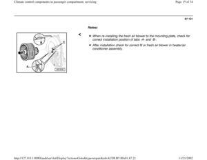
Notes for installing:
After installing, always check DTC memory
page 01
-18
.
Testing -V71- page 01
-42
(output DTM).
Electrical test page 01
-115
.
Wiring harness must be installed so that it does
not come in contact with moving components
(Eg.: motor linkage).
Metal lever -A- moves the air flow flap and is inserted in the closed
guide groove -C-. Plastic lever -B- moves the fresh air/recirculating air flap, runs mostly
on the rear of the curved disc and only assumes an open guide
groove position when in "recirculating operation."
Pa
ge 32 of 34 Climate control com
ponents in
passen
ger com
partment, servicin
g
11/21/2002 htt
p://127.0.0.1:8080/audi/servlet/Dis
play?action=Goto&t
yp
e=re
pair&id=AUDI.B5.HA01.87.21


Remove complete front section of center console
Repair Manual, Body Interior, Repair Group
70
-")


Repair Man")


- Remove heater/air conditioner assembly
complete with instrument panel page 87
-159
.
Notes: - Remove 3 sc")

Note:
Motor is installed between heater/air conditioning
assembly and bulkhead and operates the air flow
fla")
.
Electrical test page 01
-115
.")