Page 9 of 35
15-14
- Disconnect positive crankcase ventilation
connections on left and right cylinder head
covers.
- Disconnect fuel supply and return lines.
- Unclip cover on intake air housing.
- Remove both screws under cover.
- Push back and lift intake air housing upward.
- Pull vacuum hose off left side and remove
housing.
- Remove left-side cover for fuel injector lines.
- Detach accelerator pedal cable and lay clear.
- Disconnect line from Idle Air Control (IAC) valve
at throttle body.
- Disconnect harness connector at IAC valve and
throttle position sensor.
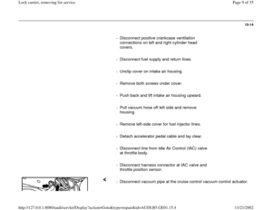
- Disconnect vacuum pipe at the cruise control vacuum control actuator.
Pa
ge 9 of 35 Lock carrier, removin
g for service
11/21/2002 htt
p://127.0.0.1:8080/audi/servlet/Dis
play?action=Goto&t
yp
e=re
pair&id=AUDI.B5.GE01.15.4
Page 10 of 35
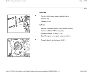
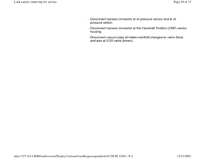
- Disconnect harness connector at oil pressure sensor and at oil
pressure switch.
- Disconnect harness connector at the Camshaft Position (CMP) sensor
housing.
- Disconnect vacuum pipe at intake manifold changeover valve (blue)
and also at EGR valve (brown).
Pa
ge 10 of 35 Lock carrier, removin
g for service
11/21/2002 htt
p://127.0.0.1:8080/audi/servlet/Dis
play?action=Goto&t
yp
e=re
pair&id=AUDI.B5.GE01.15.4
Page 11 of 35
15-15
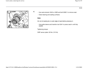
- Disconnect harness connectors for Heated
Oxygen Sensors (H02S) and oxygen sensor
heaters at engine compartment bulkhead, and
move to one side.
- Disconnect vacuum line to EGR vacuum
regulator solenoid valve at throttle body.
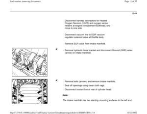
- Remove EGR valve from intake manifold.
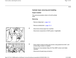
- Remove hydraulic hose bracket and disconnect Ground (GND) wires
(arrow) on intake manifold.
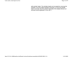
Note:
The intake manifold has two slanting mounting surfaces to the left and - Remove bolts (arrows) and remove intake manifold.
- Seal off openings using clean cloth rags.
- Disconnect coolant line at rear of cylinder head.
Pa
ge 11 of 35 Lock carrier, removin
g for service
11/21/2002 htt
p://127.0.0.1:8080/audi/servlet/Dis
play?action=Goto&t
yp
e=re
pair&id=AUDI.B5.GE01.15.4
Page 12 of 35
right cylinder heads. The cylinders heads can be warped by removing the
manifold. If only the intake manifold is removed, or if only one cylinder
head is removed, then the cylinder head bolts of the head(s) that are not
removed must be tightened 1/4-turn (90 ).
Pa
ge 12 of 35 Lock carrier, removin
g for service
11/21/2002 htt
p://127.0.0.1:8080/audi/servlet/Dis
play?action=Goto&t
yp
e=re
pair&id=AUDI.B5.GE01.15.4
Page 13 of 35
15-16
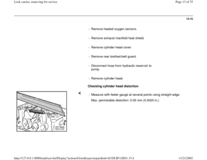
- Remove heated oxygen sensors.
- Remove exhaust manifold heat shield.
- Remove cylinder head cover.
- Remove rear toothed-belt guard.
- Disconnect hose from hydraulic reservoir to
pump.
- Remove cylinder head.
Checking cylinder head distortion
- Measure with feeler gauge at several points using straight edge.
Max. permissible distortion: 0.05 mm (0.0020 in.)
Pa
ge 13 of 35 Lock carrier, removin
g for service
11/21/2002 htt
p://127.0.0.1:8080/audi/servlet/Dis
play?action=Goto&t
yp
e=re
pair&id=AUDI.B5.GE01.15.4
Page 14 of 35
15-17
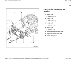
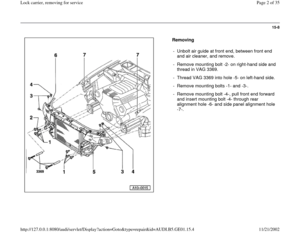
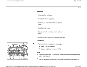
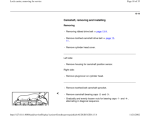
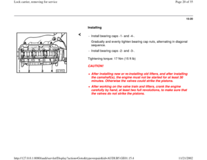
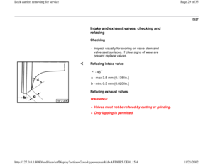
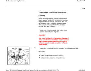
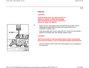
Installing
- Clean sealing surfaces.
- Install cylinder head gasket.
Lettering on gasket faces toward cylinder
head.
- Install cylinder head.
Pay attention to centering pins in cylinder
block.
- Install cylinder head bolts and tighten by hand.
Tightening
Note: - Tighten cylinder head bolts in two stages:
Stage 1 60 Nm (44 ft lb)
Stage 2 additional 1/2-turn (180 )
For final 1/2-turn, two 1/4-turns (90 ) are also permissible if tightening
with a fixed wrench. It is not necessary to retighten the cylinder head bolts after repairs, or
Pa
ge 14 of 35 Lock carrier, removin
g for service
11/21/2002 htt
p://127.0.0.1:8080/audi/servlet/Dis
play?action=Goto&t
yp
e=re
pair&id=AUDI.B5.GE01.15.4
Page 15 of 35
as part of maintenance service.
Pa
ge 15 of 35 Lock carrier, removin
g for service
11/21/2002 htt
p://127.0.0.1:8080/audi/servlet/Dis
play?action=Goto&t
yp
e=re
pair&id=AUDI.B5.GE01.15.4
Page 16 of 35
15-18
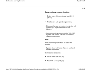
Compression pressure, checking
Engine warm-oil temperature at least 30 C
(86 F)
Throttle valve fully open during cranking
- Disconnect harness connectors from ignition coil
power output stage and from all six fuel
injectors.
- Use compression pressure recorder VAG 1381
together with adapter 1381/5 or equivalent to
measure compression.
Note:
Refer to operating instructions for use of the
recorder.
- Operate starter until tester shows no additional
increase in pressure.
Compression pressures
New: 9-14 bar (131-203 psi)
Wear limit: 7.5 bar (109 psi)
Pa
ge 16 of 35 Lock carrier, removin
g for service
11/21/2002 htt
p://127.0.0.1:8080/audi/servlet/Dis
play?action=Goto&t
yp
e=re
pair&id=AUDI.B5.GE01.15.4

 sensor
housing.
- Disconnect vacuum pipe at intak")
 and oxygen sensor
heaters at engine compartment bulkhead, and
move to one side.
- Disconnect vacuum line to EG")


Throttle valve fully open during cranking
- Disconnect harness connectors from ign")