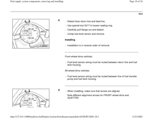
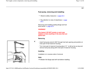
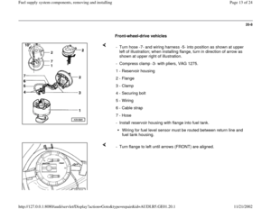
Page 17 of 24
20-11
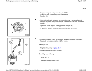
- Supply voltage to fuel pump using VAG 1551
scan tool and "Output Diagnostic Test Mode"
function 03.
- Connect multimeter between connector terminal 1 (green wire) and
terminal 4 (brown wire) using adapter cables from VW 1594 connector
test kit.
Specified value: approx. battery positive voltage (B+)
- If specified value is obtained, reconnect harness connector.
If wiring is OK:
Checking fuel delivery - Using ohmmeter, check for continuity between connector (outside of
housing), harness connector and fuel pump.
- Replace fuel pump page 20
-7 .
- Install cover for fuel pump module.
Fuse 28 OK Relay in relay position 6 OK
Pa
ge 17 of 24 Fuel su
pp
ly system com
ponents, removin
g and installin
g
11/21/2002 htt
p://127.0.0.1:8080/audi/servlet/Dis
play?action=Goto&t
yp
e=re
pair&id=AUDI.B5.GE01.20.1
Page 18 of 24
Fuel filter OK Battery fully charged
Pa
ge 18 of 24 Fuel su
pp
ly system com
ponents, removin
g and installin
g
11/21/2002 htt
p://127.0.0.1:8080/audi/servlet/Dis
play?action=Goto&t
yp
e=re
pair&id=AUDI.B5.GE01.20.1
Page 19 of 24
20-12
- Disconnect fuel return line -1- at engine compartment bulkhead and
hold in measuring container.
- Connect remote control VAG 1348/3A with auxiliary cable VAG 1348/2
to fuse 28, connect positive (+) cable to battery.
- Operate remote control for 15 seconds (hold down button).
Fuel pump check valve, checking
Testing check valve Repair Manual, 2.8 Liter V-6 OBD II Fuel Injection
Ignition, Repair Group 24 - Compare quantity of fuel delivered with specified values for minimum
fuel delivery rate in graph, according to actual voltage at fuel pump.
*) - Minimum fuel delivery rate-fuel volume in cm3 (ml) delivered in15
seconds
**) - Voltage (V) at fuel pump with engine stopped, fuel pump running-
approx. 2 volts less than battery positive voltage (B+)
Pa
ge 19 of 24 Fuel su
pp
ly system com
ponents, removin
g and installin
g
11/21/2002 htt
p://127.0.0.1:8080/audi/servlet/Dis
play?action=Goto&t
yp
e=re
pair&id=AUDI.B5.GE01.20.1
Page 20 of 24
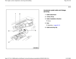
20-13
Accelerator pedal cable and linkage,
servicing
1 -
Cable attachment
2 -
10 Nm (7ft lb)
3 -
Cable installation direction
Arrow
4 -
Cam Adjusting page 20
-15
5 -
Cable securing clip
Pa
ge 20 of 24 Fuel su
pp
ly system com
ponents, removin
g and installin
g
11/21/2002 htt
p://127.0.0.1:8080/audi/servlet/Dis
play?action=Goto&t
yp
e=re
pair&id=AUDI.B5.GE01.20.1
Page 21 of 24
20-14
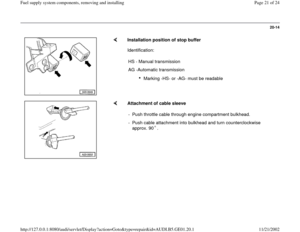
Installation position of stop buffer
Identification:
HS - Manual transmission
AG -Automatic transmission
Marking -HS- or -AG- must be readable
Attachment of cable sleeve
- Push throttle cable through engine compartment bulkhead.
- Push cable attachment into bulkhead and turn counterclockwise
approx. 90 .
Pa
ge 21 of 24 Fuel su
pp
ly system com
ponents, removin
g and installin
g
11/21/2002 htt
p://127.0.0.1:8080/audi/servlet/Dis
play?action=Goto&t
yp
e=re
pair&id=AUDI.B5.GE01.20.1
Page 22 of 24
20-15
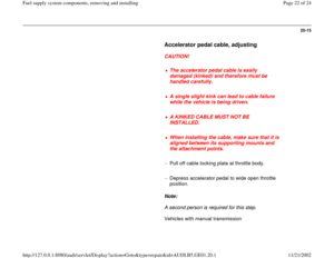
Accelerator pedal cable, adjusting
CAUTION!
The accelerator pedal cable is easily
damaged (kinked) and therefore must be
handled carefully.
A single slight kink can lead to cable failure
while the vehicle is being driven.
A KINKED CABLE MUST NOT BE
INSTALLED.
When installing the cable, make sure that it is
aligned between its supporting mounts and
the attachment points.
- Pull off cable locking plate at throttle body.
- Depress accelerator pedal to wide open throttle
position.
Note:
A second person is required for this step.
Vehicles with manual transmission
Pa
ge 22 of 24 Fuel su
pp
ly system com
ponents, removin
g and installin
g
11/21/2002 htt
p://127.0.0.1:8080/audi/servlet/Dis
play?action=Goto&t
yp
e=re
pair&id=AUDI.B5.GE01.20.1
Page 23 of 24
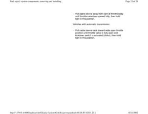
- Pull cable sleeve away from cam at throttle body
until throttle valve has opened fully, then hold
tight in this position.
Vehicles with automatic transmission
- Pull cable sleeve back toward wide open throttle
position until throttle valve is fully open and
kickdown switch is actuated (clicks), then hold
tight in this position.
Pa
ge 23 of 24 Fuel su
pp
ly system com
ponents, removin
g and installin
g
11/21/2002 htt
p://127.0.0.1:8080/audi/servlet/Dis
play?action=Goto&t
yp
e=re
pair&id=AUDI.B5.GE01.20.1
Page 24 of 24
20-16
- Insert securing clip for cable sleeve.
- Release accelerator pedal.
Note:
After adjusting the cable, check idle speed and
check the wide open throttle stop at the throttle
valve.
Pa
ge 24 of 24 Fuel su
pp
ly system com
ponents, removin
g and installin
g
11/21/2002 htt
p://127.0.0.1:8080/audi/servlet/Dis
play?action=Goto&t
yp
e=re
pair&id=AUDI.B5.GE01.20.1
Page:
< prev 1-8 9-16 17-24


 and
termina")


3 -
Cable installation direction
Arrow
4 -
Cam Adjusting page 20
-15
5 -
Cable securing cl")

 and therefore must be
handled carefully.
A single slight kink can")

