Page 25 of 64
37-95
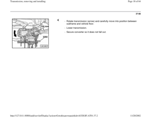
- Only perform vehicle alignment if necessary.
Repair Manual, Suspension, Wheels,
Steering, Repair Group 44; Vehicle alignment
- Install transmission supports at left and right with
transmission mount page 37
-125
Bolt torque converter to drive plate
For vehicles with hex bolts: - Remove bolt -A- after transmission is bolted to engine.
- Apply corrosion protection to contact surface between bolt -A- and oil
pan.
- Bolt torque converter to drive plate via 3 bolts using special tool V175
(turn crank shaft an additional 1/3 turn every time).
Pa
ge 25 of 64 Transmission, removin
g and installin
g
11/20/2002 htt
p://127.0.0.1:8080/audi/servlet/Dis
play?action=Goto&t
yp
e=re
pair&id=AUDI.B5.AT01.37.2
Page 26 of 64
37-96
For vehicles with Torx bolts:
Repair Manual, Electrical Equipment, Repair Group 27; Starter,
removing and installing
- Bolt 3 torque converter bolts to drive plate using respective Torx insert
(turn crank shaft an additional 1/3 turn every time).
- Install starter.
- Install ATF lines to engine/transmission subframe.
- Install bracket for ATF- line.
- Slightly raise engine/transmission subframe at rear via VAG1383A
hoist.
Repair Manual, Suspension, Wheels, Steering, Repair Group 40
- Bolt in engine speed (RPM) sensor -G28- (arrow -B-) at front left of
transmission (if installed).
- Connect connector for speedometer Vehicle Speed Sensor (VSS).
- Bolt drive axles to transmission flanges.
Pa
ge 26 of 64 Transmission, removin
g and installin
g
11/20/2002 htt
p://127.0.0.1:8080/audi/servlet/Dis
play?action=Goto&t
yp
e=re
pair&id=AUDI.B5.AT01.37.2
Page 27 of 64
37-97
- Bolt in bolts at mounting bracket of selector lever cable, install selector
lever cable and if necessary, adjust.
All-wheel-drive vehicles - Connect connector of multi-function Transmission Range (TR) switch -
1-.
- Connect connector for transmission wiring harness and secure using
securing lever -2-.
- Install shielding plate/selector lever cable
- Bolt driveshaft to transmission flange page 39
-79
, Driveshaft,
removing and installing.
Pa
ge 27 of 64 Transmission, removin
g and installin
g
11/20/2002 htt
p://127.0.0.1:8080/audi/servlet/Dis
play?action=Goto&t
yp
e=re
pair&id=AUDI.B5.AT01.37.2
Page 28 of 64
37-98
Continuation for all vehicles
Radio operating manual
Tightening torque table Page 37
-119
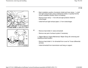
onward. - Bolt heat shield -B- for driveshaft to Torsen differential cover (arrows) if
installed.
- Install heat shield -A- above driveshaft.
- Install bracket for noise insulation panel.
- Install noise insulation panel.
- Install front wheels.
- Connect battery Ground (GND) strap.
- Check adjustment of selector lever cable page 37
-45
.
- Check gear oil in final drive with transmission installed page 39
-1 .
- Then check ATF level and top off Page 37
-133
onward.
- After connecting battery, enter anti-theft code for radio.- Fully close power windows to stop.
- Then activate all power window switches ("up") for at least one second
to activate automatic window raising/lowering.
- Set clock to correct time.
Pa
ge 28 of 64 Transmission, removin
g and installin
g
11/20/2002 htt
p://127.0.0.1:8080/audi/servlet/Dis
play?action=Goto&t
yp
e=re
pair&id=AUDI.B5.AT01.37.2
Page 29 of 64
37-99
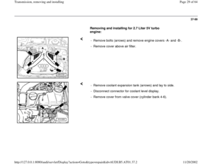
Removing and installing for 2.7 Liter 5V turbo
engine:
- Remove bolts (arrows) and remove engine covers -A- and -B-.
- Remove cover above air filter.
- Remove coolant expansion tank (arrows) and lay to side.
- Disconnect connector for coolant level display.
- Remove cover from valve cover (cylinder bank 4-6).
Pa
ge 29 of 64 Transmission, removin
g and installin
g
11/20/2002 htt
p://127.0.0.1:8080/audi/servlet/Dis
play?action=Goto&t
yp
e=re
pair&id=AUDI.B5.AT01.37.2
Page 30 of 64
37-100
- Remove air distributor (arrows).
- Remove heat sensor -1- from right turbocharger using 3035.
- Remove heat shields -2- from left and right turbochargers.
- Remove upper bolts -3- to front line to left and right turbochargers.
Pa
ge 30 of 64 Transmission, removin
g and installin
g
11/20/2002 htt
p://127.0.0.1:8080/audi/servlet/Dis
play?action=Goto&t
yp
e=re
pair&id=AUDI.B5.AT01.37.2
Page 31 of 64
37-101
- Disconnect connector -1- for oxygen sensor (right side) at bulkhead.
- Expose wire with connector to oxygen sensor.
- Disconnect connectors -2- of left oxygen sensor at bulkhead and
remove lower part of connectors from bracket.
- Expose wire with connector to oxygen sensor.
- Remove all connecting bolts for engine/transmission which can be
reached from the top.
Pa
ge 31 of 64 Transmission, removin
g and installin
g
11/20/2002 htt
p://127.0.0.1:8080/audi/servlet/Dis
play?action=Goto&t
yp
e=re
pair&id=AUDI.B5.AT01.37.2
Page 32 of 64
37-102
- Assemble both 10-222A/3 engine support
adapters for front and rear spindles on support
bar.
- Set 10-222A engine support bridge onto the fender mounting flanges
using 10-222A/1 brackets.
- Hang both spindles on the adapters.
- Secure engine to spindles. To do so, additionally use a shackle -1- at
the rear side of the engine to avoid damage.
- Take up weight of engine/transmission assembly on spindles.
- Tighten the rear spindle less, to enable later lowering at rear.
- Raise vehicle.
- Remove front wheels.
- Remove sound-deadening pan.
- Remove bracket for noise insulation panel.
Pa
ge 32 of 64 Transmission, removin
g and installin
g
11/20/2002 htt
p://127.0.0.1:8080/audi/servlet/Dis
play?action=Goto&t
yp
e=re
pair&id=AUDI.B5.AT01.37.2


 if")
 and remove engine covers -A- and -B-.
- Remove cover above air filter.
- Remove coolant expa")
.
- Remove heat sensor -1- from right turbocharger using 3035.
- Remove heat shields -2- from left and right turbochargers.
- Remove upper bolts")
 at bulkhead.
- Expose wire with connector to oxygen sensor.
- Disconnect connectors -2- of left oxygen sensor at bulkhea")
